![]() Kaluga
Kaluga
the Power Amplifier
User’s Manual
Kaluga Mono Power Amplifier
Please read this manual before operating the unit
Packing List
Your product was shipped with the items checked below. Please verify that you find all items mentioned in this list before you start setting up:
| Item | Qty | Shipper’s signature |
| Power Amplifier | 2 | |
| Power Cord | 2 | |
| Trigger Cable | 2 |
Welcome
First off, congratulations! With the purchase of this product, you have joined a growing community of audiophiles who value truthful sound reproduction and who consider neutral and transparent electronics a cornerstone in this pursuit. We at Mola Mola made it our primary goal to build electronics capable of passing a signal with no discernible change at all. Amplifiers make the signal bigger, converters turn the signal from a digital representation into an analog one. In all these processes we strive to add nothing and to remove nothing.
Our work designing Class D power amplifiers is well known. It has allowed us to achieve the utmost in coloration-free power amplification without having to resort to power-hungry class A or class AB circuitry. The Kaluga power amplifier is based on our well-known Ncore® control topology built using the discrete signal processing stages also found in the Makua pre-amplifier.
We wish you a lifetime of musical enjoyment with this product and thank you for your custom.
Mola Mola Team
Important Safety Instructions
Throughout this document, some aspects of the operation that have a potential impact on safety or reliability are noted with the words “Warning” and “Caution”. Take particular care reading and understanding these items. Paragraphs marked with “Warning” explain the safety measures required to maintain your personal safety. Paragraphs marked with “Caution” pertain to danger to the equipment itself or to connected equipment. Please follow these precautions when using this product:
- Read these instructions.
- Keep these instructions.
- Follow all instructions.
- Heed all warnings.
- Install in accordance with the manufacturer’s instructions.
- Use only attachments or accessories specified by the manufacturer.
- WARNING: Dangerous voltage is inside this apparatus. Opening is only allowed by qualified service personnel.
- WARNING: Do not defeat the safety purpose of the safety earth connection. Use the provided three-prong power cord to insure the product is connected to safety earth. If the provided mains cord does not fit your outlet, consult an electrician for replacement of the obsolete outlet.
- Protect the power cord from being walked on or pinched, particularly at plugs, convenience receptacles, and the point where they exit from the apparatus.
- Unplug this apparatus during lightning storms or when unused for long periods of time.
- WARNING: Do not use this apparatus near water. Do not expose the apparatus to dripping or splashing. Do not place objects filled with liquids (flower vases, drink cans, coffee cups, etc) on the apparatus. Do not use this apparatus out of doors.
- WARNING: Clean only with a dry, soft, lint-free cloth. Do not spray any liquid cleaner onto the cabinet, as this may lead to dangerous shocks or malfunction.
- CAUTION: This unit runs slightly warm when operated normally. Operate in a normally ventilated area.
- CAUTION: Do not install near any heat sources such as radiators, heat registers, stoves, or other apparatus (including amplifiers) that produce heat. Avoid exposure to direct sunlight.
- Use only with a cart, stand, bracket, or table designed for use with audio or music equipment. In any installation, make sure that injury or damage will not result from cables pulling on the apparatus and its mounting.
- Refer all servicing to qualified service personnel. Servicing is required when the apparatus has been damaged in any way, such as when the power-supply cord or plug is damaged, liquid has been spilled or objects have fallen into the apparatus, the apparatus has been exposed to rain or moisture, does not operate normally, or has been dropped.
- WARNING: To reduce the risk of fire or electric shock, do not expose this apparatus to rain or moisture.
Connections & Controls
Rear
| # | Function | Notes |
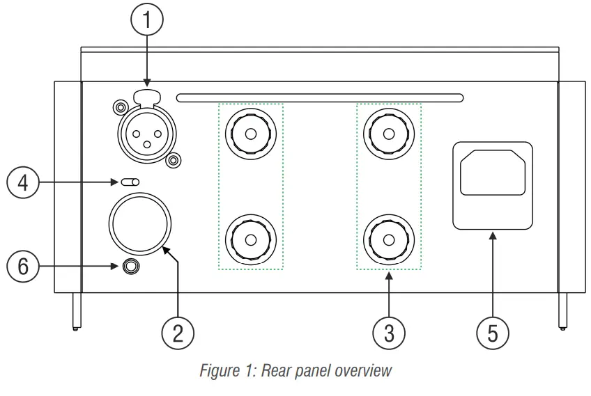
| 1 | Analogue input, balanced | |
| 2 | Analogue input, unbalanced | Covered. Pry off to access. |
| 3 | Speaker Outputs | 2 pairs of binding posts, bi-wired |
| 4 | (Un)Balanced toggle switch | |
| 5 | Mains power input | |
| 6 | Trigger Input | 2-15V, AC or DC |
Table 1: Rear panel overview
Front
| # | Function | Notes |
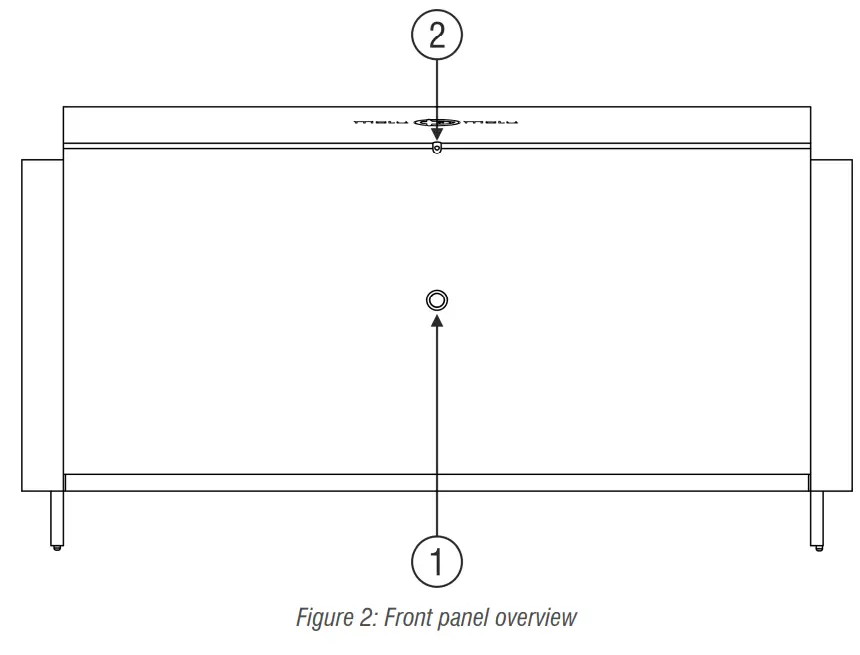
| 1 | Power button | |
| 2 | Power LED | 1 LED, white or dim red |
Table 2: Front panel overview
Setting Up
Installation
This product relies on free convection of air along the sides and top for cooling. Avoid placing magazines, books or other objects on top of the product as this acts as thermal
insulation. Installation inside a cupboard is permissible provided at least 30cm (12”) of free space above the product and 10cm (4”) around the sides is respected. Operation in closer quarters requires some provision of forced convection (fan) to be installed inside the cupboard.
AC Power Input
Connect the supplied power cord to the AC input receptacle on the rear panel. Do not connect the power cord until all the audio input and output connections have been made. It is usually best to plug the product directly into a wall outlet. Avoid the use of extension cords. A heavy duty multi-tap power outlet strip may be used if it and the wall outlet are rated to handle the total current demanded by the components connected to it.
If you are going to be away from home for an extended period of time such as a monthlong vacation, it is a sensible precaution to unplug electronic equipment. Do the same as a precautionary measure during thunderstorms. No amount of surge protection or mains filtering will save your equipment from a lightning strike in the backyard.
Input Connections
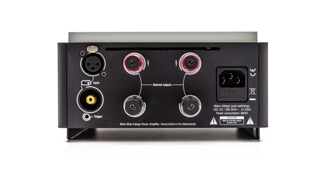
Your power amplifier accepts both RCA and XLR type connectors. If your sources have both RCA and XLR outputs, it is exceedingly likely that using the XLR connection sounds best. Depending on which you choose, set the toggle switch to the corresponding input. The RCA input is covered with a black panel plug.
Output connections
Two pairs of binding posts are provided for the purpose of bi-wiring. Both pairs are completely identical and are wired directly to the circuit board for minimum resistive coupling between the two outputs. The output impedance of the power amplifier is so low that sonically bi-wiring comes a substantial way towards the performance of bi-amping, much more so than with other power amplifiers.
Trigger inputs
Connect a 3.5mm jack cable, such as the cable supplied with your power amplifier, to a trigger source such as the trigger output on the Makua preamplifier or the Tambaqui. Any standard 3.5mm jack/jack cable will do (mono or stereo).
Basic operation
Front Panel Operation
So long as mains power is applied the power LED can be in two states: on or standby. In standby mode, it will light up a dim red (barely visible in daylight, bright red standby LEDs lighting up the room at night is a pet peeve of the designer). Push the front button to wake up the power amp. The power LED lights up white. Push again to turn the power amp off.
Trigger Operation
When the 12V trigger comes on, the power amp turns on. If the power amp was already on when the trigger came on, nothing happens. When the 12V trigger is removed, the power amp turns off. If the power amp had already been powered down manually, nothing happens.
Troubleshooting
Most difficulties in audio systems are the result of incorrect connections or improper control settings. If you encounter problems, isolate the area of the difficulty, check the
control settings, determine the cause of the fault and make the necessary changes. If you are unable to get sound from your amplifier or its behavior is not as expected, refer to the suggestions for the following conditions:
No response to the mains button: Verify the mains connection. Unplug the power cable from the Kaluga and try to power another device with it. If this works, check the fuse. Lever out the little drawer underneath the mains input and replace the fuse that is hooked into the end of it. The second fuse that you see in a separate cavity of the fuse drawer is a spare. If the unit still does not work, contact your local retailer. The unit may need repair.
The unit responds (as witnessed by lights and clicking relays) but no sound: Verify that the toggle switch on the input is correctly set (RCA or XLR). Verify correct speaker wiring. In particular, note that the positive terminals are in the top row and the negative terminals are in the bottom row. Meaning that you should connect the speaker between an upper and a lower terminal, not between two upper or two lower terminals.
Quiet, distorted sound with interruptions: You probably have a short across the speaker or amplifier terminals, for instance, two uninsulated spade terminals touching. Reinstall your speaker cable.
Audio performance data
| Item | Symbol | Min | Typ | Max | Unit | Notes |
| Output Power | Pr | 400 | W | 8 ohms. Measured with 230V mains. | ||
| Gain | Ay | 28 | dB | |||
| Input impedance | Zin | 100k | Ohm | |||
| Output Impedance | Zout | 2m | Ohm | DF=4000 | ||
| Signal-to-noise ratio | SNR | 128 | dB | Unweighted | ||
| Distortion | .002 | .005 | % | IMD, THD | ||
| Bandwidth | BW | DC | 50k | Hz | -3dB |
Table 3: Audio Performance Data
Technical data
| Item | Value | Notes |
| Supply voltage | 90-135 / 180 — 270 Volt AC/47-63Hz | Auto Switching |
| Power Consumption | 30 Watt (idle), 1350 Watt (max power) | |
| Dimensions | 215mm*110mm*340mm | (W x H x D) |
| Weight | 9 kg |
Table 4: Technical Data
Revision History
| Revision | Description | Date |
| RO | Initial draft | 29-05-2013 |
| R1 | Revised and expanded | 20-05-2014 |
| R2 | Rear panel overview updated | 11-09-2015 |
| R3 | Correct imperial free space value | 26-06-2017 |
| R4 | New layout | 10-03-2020 |
| R5 | Updated drawings | 31-03-2020 |
| R6 | Packing list updated | 10-10-2021 |
![]() Mola Mola
Mola Mola
Kattegat 8
9723 JP Groningen
The Netherlands
+31 50 526 4993
[email protected]
www.mola-mola.nl
Kaluga
Power Amplifier
R6


