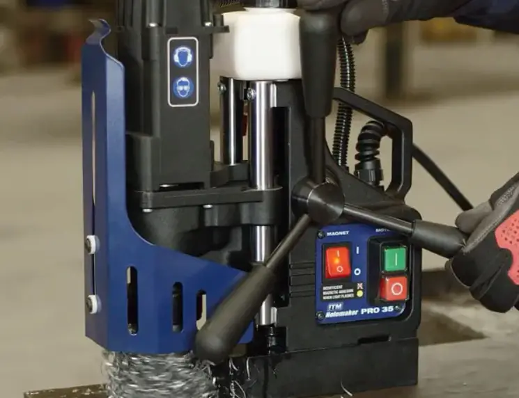
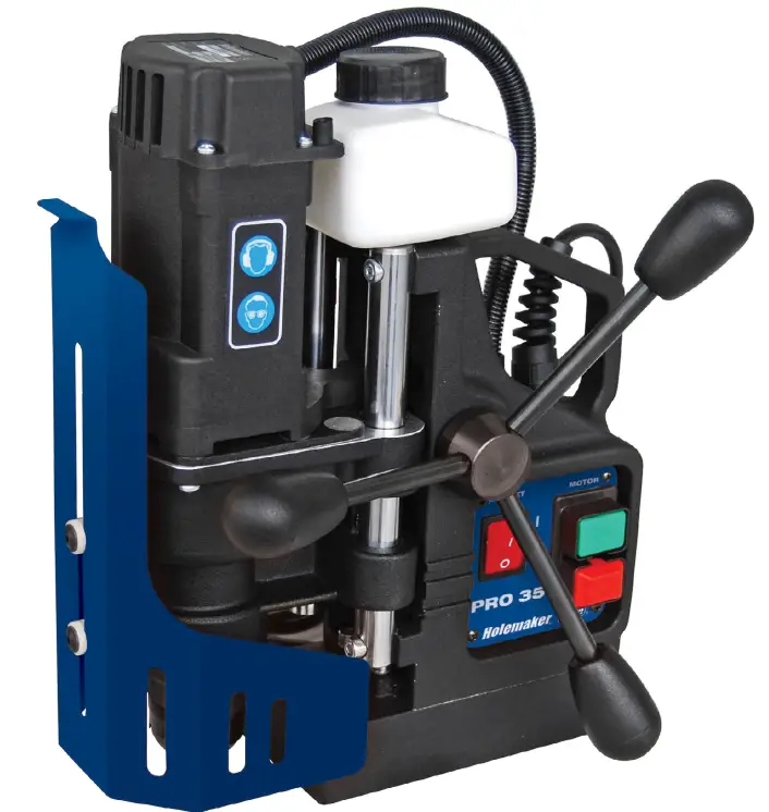
Holemaker HMPRO35 PRO 35 Magnetic Base Drilling Machine
GENERAL INFORMATION
Application
The PRO 35 is a drilling machine designed to drill holes with diameters of up to 35 mm to a depth of up to 52 mm by using annular cutters.
The electromagnetic base clamps the machine to ferromagnetic surfaces. This makes sure that the operator is safe and the machine works correctly. A safety strap protects the machine from falling in case of a clamping loss.
An optional vacuum pad allows you to clamp the machine to non-ferromagnetic surfaces.
Technical data
| Voltage | 1~ 110–120 V, 50–60 Hz 1~ 220–240 V, 50–60 Hz |
| Power | 1020 W |
| Tool holder | 19 mm (3/4″) Weldon |
| Maximum drilling diameter | 35 mm |
| Maximum drilling depth | 52 mm |
| Clamping force surface with the thickness of 25 mm (0.98”) and roughness Ra = 1.25 | 9 500 N |
| Electromagnetic base dimensions | 80 mm × 160 mm × 38 mm |
| Stroke | 70 mm |
| Rotational speed with load | 350 rpm |
| Minimum workpiece thickness | 6 mm |
| Protection class | I |
| Protection level | IP 20 |
| Noise level | More than 85 dB |
| Required ambient temperature | 0–40°C |
| Weight | 10 kg |
Equipment included
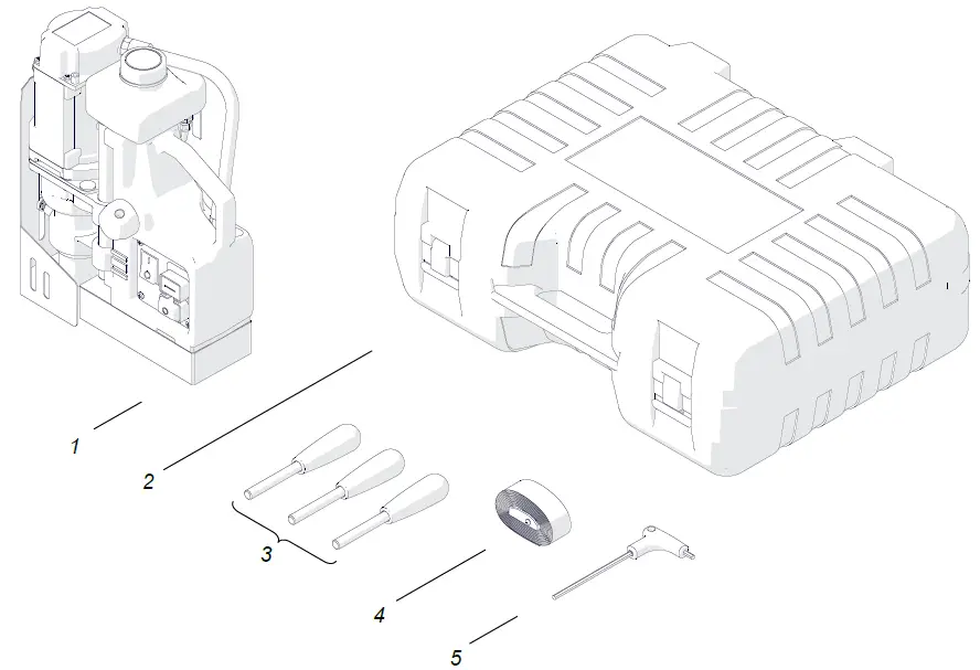
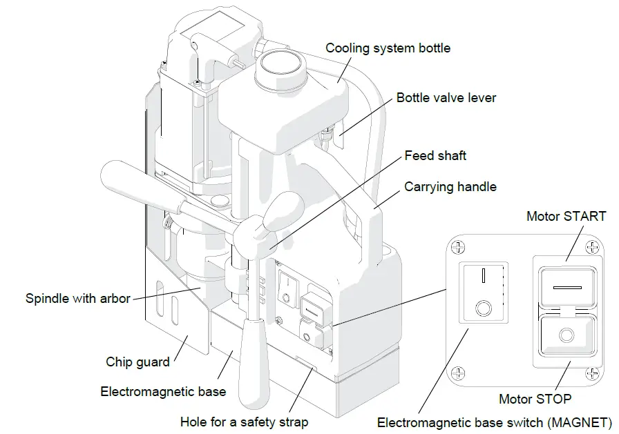
1 | Drilling machine with a cooling system bottle and a chip guard | 1 unit |
2 | Plastic box | 1 unit |
3 | Handle | 3 units |
4 | Safety strap | 1 unit |
5 | 4 mm hex wrench with a handle | 1 unit |
– | Operator’s manual | 1 unit |
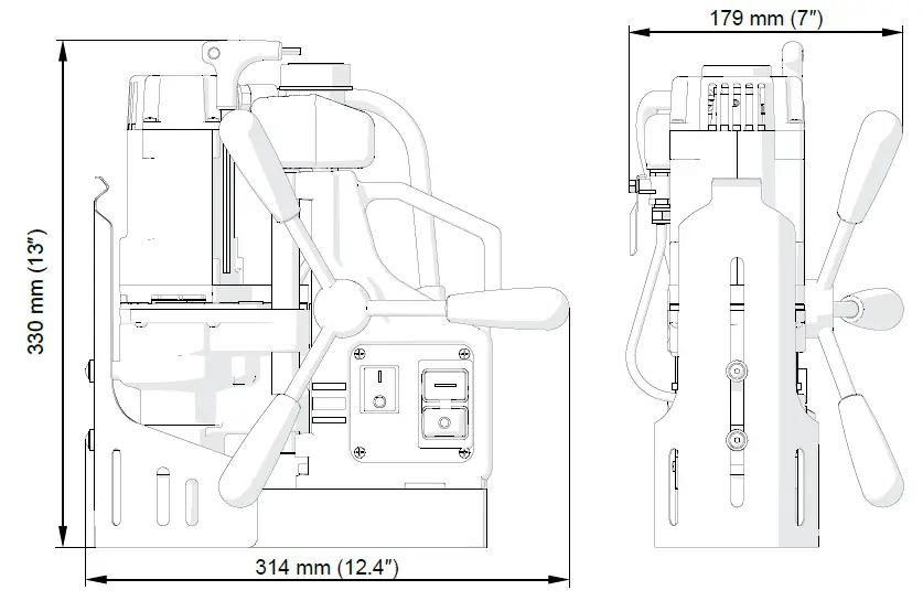
Dimensions
Design
SAFETY PRECAUTIONS
- Before use, read this operator’s manual and complete a training in occupational safety and health.
- Use only in applications specified in this operator’s manual.
- Make sure that the machine has all parts and they are genuine and not damaged.
- Make sure that the specifications of the power source are the same as those specified on the rating plate.
- Connect the machine to a correctly grounded power source. Protect the power source with a 16 A fuse for 230 V or a 32 A fuse for 115 V. If you are going to work on building sites, supply the machine through an isolation transformer with class II protection only.
- Do not carry the machine by the power cord and do not pull the cord. This can cause damage and electric shock.
- Set the MAGNET switch to ‘O’ before you move the machine. Use carrying handle to move the machine.
- Keep untrained bystanders away from the machine.
- Before each use, ensure the correct condition of the machine, power source, power cord, plug, control panel, and tools.
- Before each use, make sure that no part is cracked or loose. Make sure to maintain correct conditions that can have an effect on the operation of the machine.
- Keep the machine dry. Do not expose the machine to rain, snow, or frost.
- Do not stay below the machine that is put at heights.
- Keep the work area well-lit, clean, and free of obstacles.
- Make sure that the tool is correctly attached. Remove wrenches from the work area before you connect the machine to the power source.
- Do not use tools that are dull or damaged.
- Unplug the power cord before you install and remove tools. Use protective gloves to install and remove tools.
- Use annular cutters without the pilot pin only when you drill incomplete through holes.
- Do not drill holes whose diameter or depth differ from those specified in the technical data.
- Do not use in explosive environments or near flammable materials.
- Do not use on surfaces that are rough, not flat, not rigid, or have rust, paint, chips, or dirt.
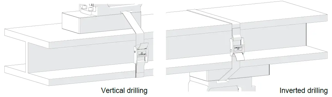
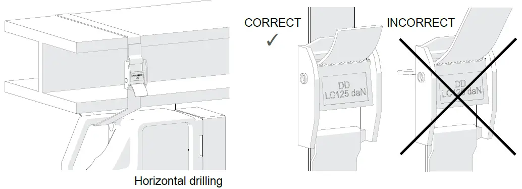
- Use the safety strap to attach the machine to a stable structure. Put the strap through the hole in the machine body. In the horizontal position, attach the strap to the carrying handle. Do not put the strap into the buckle from the front.
- Use eye and ear protection and protective clothing. The clothing must not be loose.
- Be careful when drilling in plates thinner than 10 mm (0.4″). The clamping force depends on plate thickness and is much lower for thin plates.
- Each time before you put the machine on the workpiece, rub the workpiece with coarse-grained sandpaper. Make sure that the full bottom of the base touches the surface.
- Do not touch chips or moving parts. Do not let anything catch in moving parts.
- After use, clean the machine and the tool. Do not remove chips with bare hands.
- Unplug the power cord before you do maintenance or install/remove parts.
- Repair only in a service center appointed by the seller.
- If the machine falls, is wet, or has any damage, stop the work and immediately send the machine to the service center for check and repair.
- Do not leave the machine when it operates.
- If you are not going to use the machine, remove the cutter and the pilot pin from the holder. Then, remove the machine from the work area and keep it in a safe and dry place.
- If you are not going to use the machine for an extended period, put anti-corrosion material on the steel parts.
SYMBOLS
Before using the machine, read the description of the following symbols.
- Warning against electric voltage

- Wear eye protection

- Wear ear protection

- Refer to instruction manual


STARTUP AND OPERATION
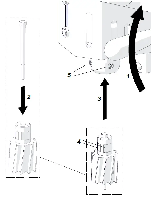
Installing and removing the annular cutter
- Unplug the power cord.
- Turn the handles to the right (1) to lift the motor.
- Use gloves to put the correct pilot pin into the cutter (2).
- Use a dry cloth to clean the spindle and the cutter.
- Put the cutter into the spindle (3) so that the flat surfaces (4) align with the screws (5).
- Use the 4 mm hex wrench to tighten the screws.
- To remove the cutter, loosen the screws (5) with the 4 mm hex wrench.

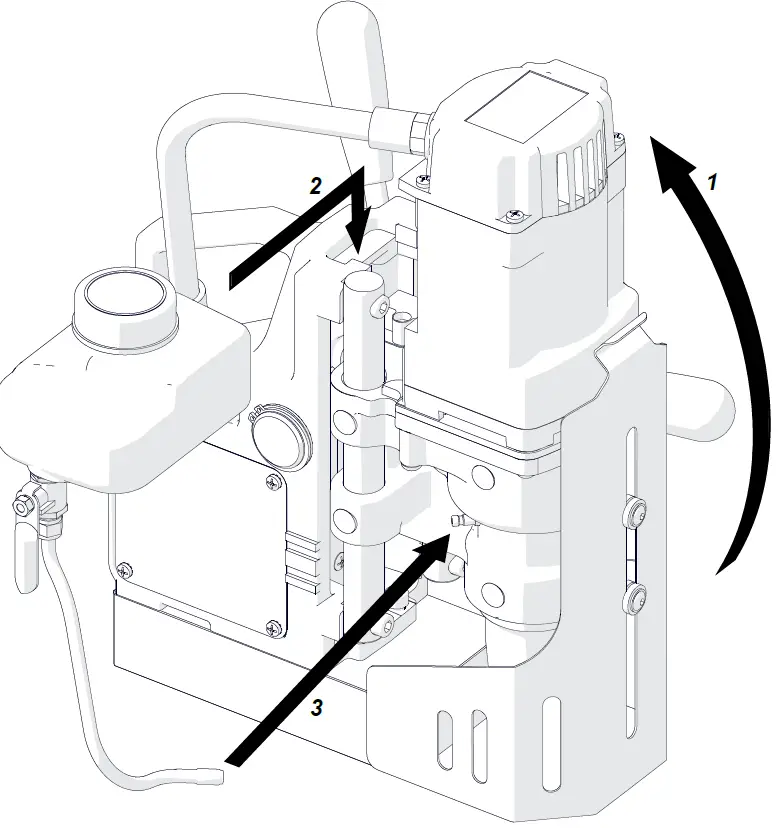
Installing and removing the cooling system
- Turn the handles to lift the motor (1).
- Put the bottle on the machine (2).
- Attach the hose to the fitting (3).
- To remove the bottle, first detach the hose and lift the motor.

Preparing
- Before use, clean steel parts, including the spindle, from anti-corrosion material used to preserve the machine for storage and transport.
- Attach the handles to the feed shaft. The machine can help the work of a left-handed person or in hard-to-reach places. To do this, install the feed shaft so that the handles are on the opposite side of the machine.
- Select the annular cutter that matches the required hole diameter. Use a dry cloth to clean the spindle and the cutter. Then, install the cutter as described before.
Put the machine on a flat ferromagnetic surface that is at least 6 mm (0.24″) thick. Connect the machine to the power source. Set the MAGNET switch to ‘I’ to turn on the clamping.
WARNING:
- The clamping force of electromagnetic base will be lower if there is rust, paint, chips, or dirt on the surface of the workpiece. The clamping force will be lower also if the surface is thin, rough, not flat, not rigid, the voltage is lower than required, or the bottom of the base is worn. Some types of steel (non-ferromagnetic) do not conduct magnetic flux so the machine cannot clamp onto them.
- Use the safety strap to prevent fall and injury if the machine loses the clamping. Attach the machine to a stable structure by putting the strap through the hole in the machine body. In the horizontal position, attach the strap to the carrying handle. Make sure that the strap is tight and not twisted. If the machine comes loose from the workpiece and hangs on the strap, replace the strap. Do not put the strap into the buckle from the front.


- Turn the handles to the left to put the cutter above the workpiece. For vertical drilling, fill the cooling system bottle with coolant. Do not use only water as the coolant. But you can mix water and drilling oil. Then, make sure that the cooling system works correctly. To do this, lightly loosen the bottle cap and use the lever to open the bottle valve. Then, turn the handles to the left to apply a light pressure on the pilot pin. The coolant should fill the system and start flowing from the cutter.
- The cooling system works by gravity. Thus, in the inverted or horizontal position, use coolants under pressure or in the form of spray or paste. Do not allow coolant to run into the motor.
Drilling
Press the green Motor START button to start the motor. Turn the handles to the left to put the cutter into the workpiece.
WARNING: When the cutter goes through the workpiece, the slug core is pushed out with a large force.
Drill only through holes. For incomplete through holes do not use the pilot pin.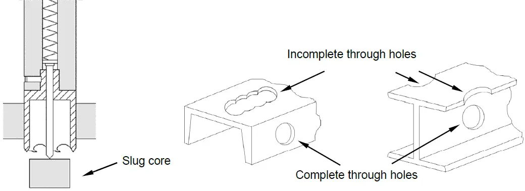
Keep the machine in the same position until the hole is made. After you get to the depth of 40 mm (1.6″), remove the cutter from the workpiece as often as possible. Then, manually apply the coolant from the bottle into the drilling area.
After drilling the hole, remove the cutter from the workpiece. Then, press the red Motor STOP button to turn off the motor. Before you move the machine, set the MAGNET switch to ‘O’ to turn off the base.
After use, turn off the motor and the base, and then unplug the power cord. Clean the machine and the cutter, and then remove the machine from the work area.
Tighten the bottle cap, close the valve, and then press the pilot pin to remove the coolant that remains in the cooling system. Use gloves to remove the cutter and the pilot pin from the arbor, and then put the machine into the box.
Replacing the brushes
At intervals of 100 work hours, check the condition of the brushes.
- To do this, unplug the power cord and remove the cover (1).
- Next, remove the pressing plate (2), and then remove the brush holder (3) and the brush (4).
- If the brush is shorter than 5 mm (0.2″), replace the two brushes with new ones.
- Install in reverse sequence. Then, let the motor operate with no load for 20 minutes.
WARNING: All electrical work, including replacing brushes, must be made by a qualified and licensed electrician.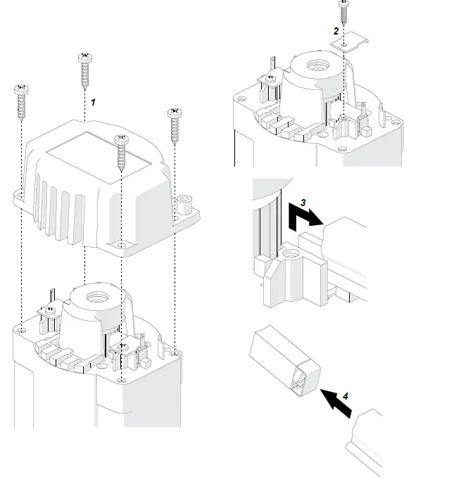
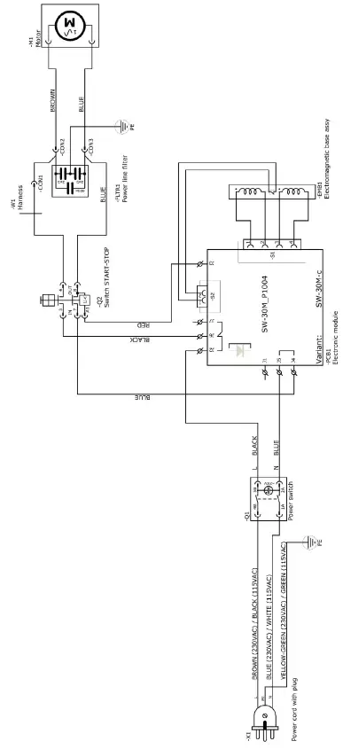
WIRING DIAGRAM
PARTS BREAKDOWN
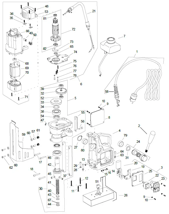
ITEM | PART NUMBER | DESCRIPTION | Q-TY |
1 | SZN-0212-10-02-00-1 | POWER CORD 230V 3×1 WITH STRAIN RELIEF ASSY (AU) | 1 |
2 | SPPRO3508 | SPOKE HANDLE WITH KNOB ASSY | 3 |
3 | PNL-0440-27-00-00-1 | CONTROL PANEL ASSY – 230V | 1 |
4 | KRP-0440-01-01-00-3 | BODY ASSY | 1 |
5 | RDK-0440-02-00-00-3 | GEARBOX ASSY | 1 |
6 | SLN-0440-03-00-00-5 | MOTOR ASSY – 230V | 1 |
7 | SPPRO3505 | COOLANT BOTTLE ASSY | 1 |
8 | SCN-0440-07-00-00-0 | BODY COVER | 1 |
9 | PDK-000161 | EXTERNAL TOOTH LOCK WASHER 3.7 | 8 |
10 | WKR-000415 | CROSS RECESSED PAN HEAD SELF-TAPPING SCREW 3.5×13 | 8 |
11 | SPHM3020 | SELF-TAPPING SCREW 5×30 | 3 |
12 | WKR-000237 | SELF-TAPPING SCREW 5×50 | 1 |
13 | WKR-000112 | CROSS RECESSED OVAL COUNTERSUNK HEAD SCREW M4x16 | 1 |
14 | NKR-000013 | HEX NUT M4 | 2 |
15 | PDK-000060 | EXTERNAL TOOTH LOCK WASHER 4.3 | 1 |
16 | PDK-000043 | SPRING WASHER 4.1 | 1 |
17 | SRB-000118 | HEX SOCKET HEAD CAP SCREW M6x30 | 2 |
18 | SRB-000123 | HEX SOCKET HEAD CAP SCREW M6x35 | 2 |
19* | STR-0257-04-03-00-9 | ELECTRONIC CONTROLLER SW 30M-C – 230V | 1 |
20* | FLT-0257-04-12-00-0 | INTERFERENCE ELIMINATOR | 1 |
21 | SPPRO350303 | MOTOR CORD ASSY | 1 |
22 | SPHM300405 | MAGNET SWITCH | 1 |
23 | SPHM300404 | START-STOP SWITCH – 230V | 1 |
24 | WLK-0271-01-02-00-1 | PINION SHAFT ASSY | 1 |
25 | SPPRO350601 | PANEL PLATE ASSY | 1 |
26 | SPPRO35014V1 | ELECTROMAGNETIC BASE | 1 |
27 | SPHM300108 | EXTERNAL RETAINING RING 28z | 1 |
28 | PDK-000046 | SPRING WASHER 6.1 | 2 |
| 29 | SRB-000114 | HEX SOCKET HEAD CAP SCREW M6x20 | 2 |
30* | SPPRO350202 | SPINDLE ASSY | 1 |
31 | SPPRO350121 | BRAKE RING 20x28x3,9 | 1 |
32 | SPPRO35023 | PINION SHAFT ASSY | 1 |
33* | SPPRO35025 | GEAR z52 | 1 |
34* | PDK-000264 | DISTANCE RING | 1 |
35 | SPPRO350315 | BRUSH HOLDER PRESSURE PLATE | 2 |
36 | WKR-000326 | CROSS RECESSED COUNTERSUNK HEAD SHEET METAL SCREW 2.9×13 | 2 |
37 | SPPRO350207 | GUIDE | 2 |
38 | LOZ-000047 | BALL BEARING 25x47x12 | 1 |
39 | LOZ-000072 | BALL BEARING 9x26x8 | 1 |
40 | SPPRO3502020 | PLUNGER | 1 |
| 41 | SPHM3020203 | SPRING | 1 |
42 | KRP-0272-02-02-01-0 | SPINDLE BODY | 1 |
43 | KZK-0279-02-01-06-2 | RUBBER DISC | 1 |
44 | SPHM30020205 | INTERNAL RETAINING RING 19w | 1 |
45 | WKR-000059 | HEX SOCKET SET SCREW WITH FLAT POINT M8x10 | 2 |
46 | LOZ-000048 | BALL BEARING 25x47x12 | 1 |
47 | SPAD40-05-03 | HOSE FITTING | 1 |
48 | WKR-000241 | SELF-TAPPING SCREW 4×20 | 4 |
49 | SPPRO350314 | MOTOR BRUSH 6x9x17 | 2 |
50 | SPPRO350313 | BRUSH HOLDER | 2 |
51 | WZK-0242-04-00-00-0 | REED RELAY WIRE SET ASSY | 1 |
52 | LOZ-000053 | BALL BEARING 8x22x7 | 1 |
ITEM | PART NUMBER | DESCRIPTION | Q-TY |
53 | SPPRO350312 | MOTOR COVER | 1 |
54 | PRS-000070 | SEAL 25x37x7 | 2 |
55 | SPPRO350212 | GEAR RACK | 1 |
56 | SRB-000111 | HEX SOCKET HEAD CAP SCREW M6x18 | 1 |
57 | SPPRO3509 | BOTTOM SLEEVE | 2 |
58 | SPPRO350704 | CABLE GLAND WITH STRAIN RELIEF PG11 | 1 |
59 | SPPRO3504 | CHIP GUARD ASSY | 1 |
60 | SPPRO3511 | NYLON WASHER 8.1x14x3 | 4 |
61 | SPPRO3510 | PUSH SPRING | 2 |
62 | SPPRO3512 | HEX SOCKET ROUND HEAD SCREW WITH FLANGE M5x20 | 2 |
63 | PDK-000176 | EXTERNAL TOOTH LOCK WASHER 6.3 | 1 |
64 | SRB-000113 | HEX SOCKET HEAD CAP SCREW M6x20 | 1 |
65 | USZ-000055 | SEAL | 1 |
66 | OBD-0272-03-01-01-3 | FILED FRAME | 1 |
67 | PDK-0279-02-01-06-1 | STEEL WASHER | 1 |
68 | SPPRO350318 | BEARING INSERT 19×7.5 | 1 |
69 | SPPRO36AD209 | STATOR – 220V | 1 |
70 | OSL-0271-03-01-02-1 | FAN COVER | 1 |
71 | WKR-000241 | SCREW FOR PLASTIC 4×20 | 1 |
72 | SPPRO35039 | ROTOR – 220V | 1 |
73 | SPPRO36AD13 | GEARBOX COVER RING | 1 |
74 | PKR-0440-03-03-00-1 | GEARBOX COVER | 1 |
75 | SPHM300304 | CROSS RECESSED PAN HEAD TAPPING SCREW | 1 |
76 | WKR-000301 | CROSS RECESSED PAN HEAD SELF-TAPPING SCREW 5×14 | 2 |
77 | PDK-000042 | SPRING WASHER 4.1 | 2 |
78 | SRB-000062 | HEX SOCKET HEAD CAP SCREW M4x12 | 2 |
79 | SPPRO35012A | SLIDE BUSHING WITH BEVEL 28x32x12 | 1 |
80 | TLJ-000034 | SLIDE BUSHING 28x32x12 | 1 |
81 | LOZ-000210 | BALL BEARING 7x16x6 | 1 |
82 | LOZ-000209 | BALL BEARING 9x24x7 | 1 |
– | SMR-000001 | GREASE | 0.055kg |
-* | PWD-271-04-06-00-0 | CONNECTING CABLE | 1 |
| Cutter Type | Features | Diameter Available | Cut Depth Available | Applications |
Silver Series Metric |
|
|
|
|
Silver Series Imperial |
|
|
|
|
Gold Series Metric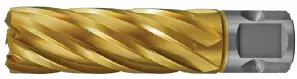 |
|
|
|
|
Pro-Cut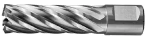 |
|
|
|
|
Maxi-Cut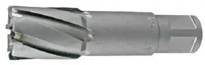 |
|
|
|
|
Maxi-Rail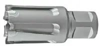 |
|
|
|
|
Countersink Type | Size | Angle |
Cross Hole Countersinks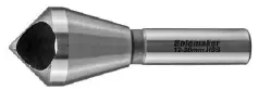 |
|
|
Three Flute Countersinks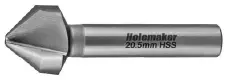 |
|
|
Twist Drill Type | Features | Diameter Available | Cut Depth Available |
Weldon Shank Twist Drills Single Piece Type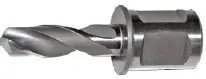 |
|
|
|
Weldon Shank Twist Drills 2-Piece Type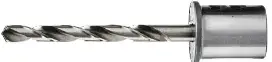 |
|
|


