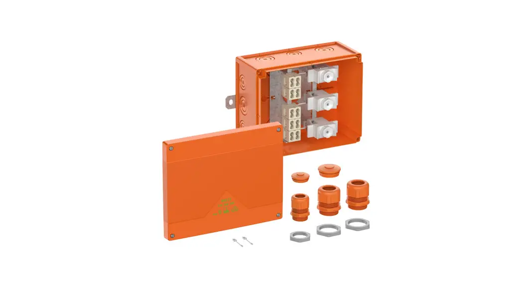
![]() WKE 200-400 Junction Box
WKE 200-400 Junction Box
Instructions
WKE 200-400 Junction Box
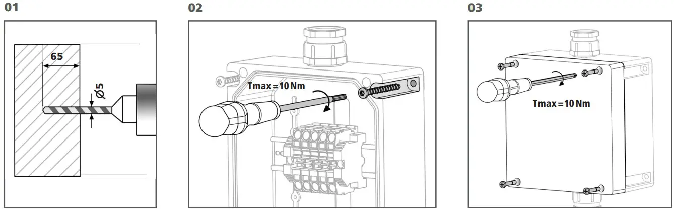
Installation on wall and ceiling
The WKE 200-400 SL is installed on the wall and on the ceiling as described in the “General building inspection test certificate” (AbP-Nr. P-1040 DMT DO).
The screw anchors that come with a fire protection approval are approved for cracked and uncracked concrete of strength categories C20/25 to C50/60 (See Figures 01 and 02). Drainage openings must be integrated as needed as per DIN EN 60670.
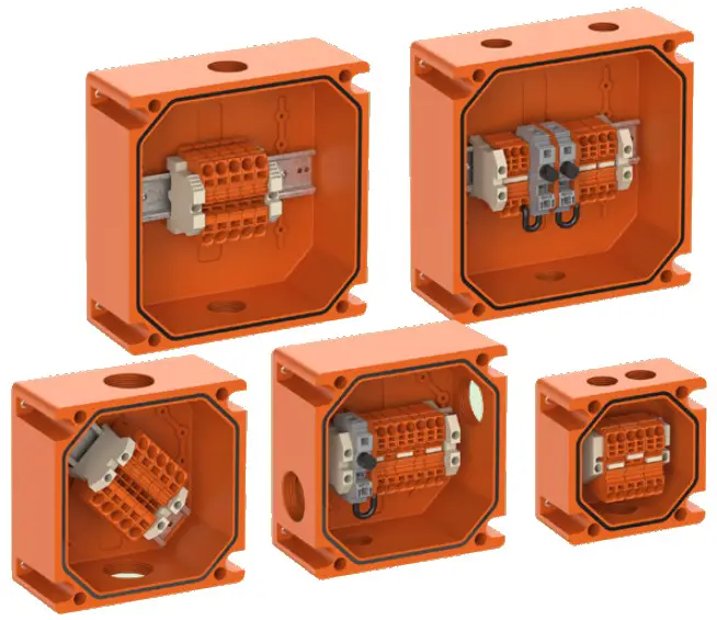
Connection of lines (depending on the enclosure size)
| mm2 | mm2 0,5 – 6 | mm2 2,5 – 6 | mm 13 – 15 | 600V | 41 A | |
| 6 | ||||||
| 10 | 0,5 – 10 | 4-10 | 17 – 19 | 600V | 57A | |
| 16 | 0,5 – 16 | 6-16 | 18 – 20 | 600V | 76A | |
| 6mm2 (Sicherungsklemme / fuse terminal block) | 0,2 – 6 | 12-13 | 500 V | 10 A | 2,5 W |
| M20 | 6 – 13 |
| M25 | 6 – 15 |
| M32 | 9 – 19 |
| M40 | 17 – 27 |
| M50 | 23 – 34 |
Günther Spelsberg GmbH + Co. KG
Im Gewerbepark 1, D-58579 Schalksmühle
Phone: +49 2355 892-0
Fax: +49 2355 892-299
E-Mail: [email protected]
Internet: www.spelsberg.de


