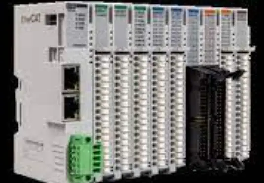
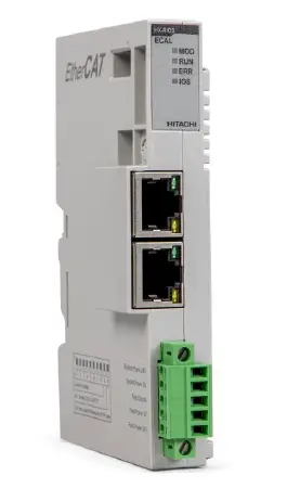
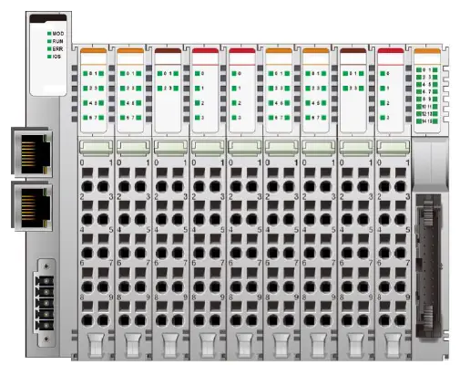
HITACHI RIO3-ECAL EtherCAT Network Adapter Light
Important Notes
Solid state equipment has operational characteristics differing from those of electromechanical equipment. Safety Guidelines for the Application, Installation and Maintenance of Solid State Controls describes some important differences between solid state equipment and hard-wired electromechanical devices.
Because of this difference, and also because of the wide variety of uses for solid state equipment, all persons responsible for applying this equipment must satisfy themselves that each intended application of this equipment is acceptable.
In no event will HITACHI be responsible or liable for indirect or consequential damages resulting from the use or application of this equipment.
The examples and diagrams in this manual are included solely for illustrative purposes. Because of the many variables and requirements associated with any particular installation, HITACHI cannot assume responsibility or liability for actual use based on the examples and diagrams.
Warning!
If you don’t follow the directions, it could cause a personal injury, damage to the equipment or explosion
- Do not assemble the products and wire with power applied to the system. Else it may cause an electric arc, which can result into unexpected and potentially dangerous action by field devices. Arching is explosion risk in hazardous locations. Be sure that the area is non-hazardous or remove system power appropriately before assembling or wiring the modules.
- Do not touch any terminal blocks or IO modules when system is running. Else it may cause the unit to an electric shock or malfunction.
- Keep away from the strange metallic materials not related to the unit and wiring works should be controlled by the electric expert engineer. Else it may cause the unit to a fire, electric shock or malfunction.
Caution!
If you disobey the instructions, there may be possibility of personal injury, damage to equipment or explosion. Please follow below Instructions.
- Check the rated voltage and terminal array before wiring. Avoid the circumstances over 55℃ of temperature. Avoid placing it directly in the sunlight.
- Avoid the place under circumstances over 85% of humidity.
- Do not place Modules near by the inflammable material. Else it may cause a fire.
- Do not permit any vibration approaching it directly.
- Go through module specification carefully, ensure inputs, output connections are made with the specifications. Use standard cables for wiring.
- Use Product under pollution degree 2 environment.
Safety Instruction
Symbols
| DANGER
| Identifies information about practices or circumstances that can cause an explosions in a hazardous environment, which may lead to personal injury or death property damage or economic loss. |
| IMPRTANT | Identifies information that is critical for successful application and understanding of the product. |
 | Identifies information about practices or circumstances that can lead to personal injury, property damage, or economic loss. Attentions help you to identity a hazard, avoid a hazard, and recognize the consequences. |

Safety Notes
![]()

The modules are equipped with electronic components that may be destroyed by electrostatic discharge. When handling the modules, ensure that the environment (persons, workplace and packing) is well grounded. Avoid touching conductive components, e.g. G-BUS Pin Pin.
Environment Specification
| Environment Specification | |
| Operating Temperature | -20℃~60℃ : 1.0A full load is allowed. |
| UL Temperature | -20℃~60℃ |
| Storage Temperature | -40℃~85℃ |
| Relative Humidity | 5% ~ 90% non-condensing |
| Mounting | DIN rail |
| General Specification | |
| Shock Operating | IEC 60068-2-27 |
| Vibration resistance | Based on IEC 60068-2-6 |
| Industrial Emissions | EN 61000-6-4/A11 : 2011 |
| Industrial Immunity | EN 61000-6-2 : 2005 |
| Installation Position | Vertical and horizontal installation is available. |
| Product Certifications | CE, UL, EAC |
General Description
RIO3 ECAL Specification
| Items | Specification |
| Communication Interface Specification | |
| Adapter Type | Slave Node (EtherCAT ID) |
| Max. Expansion Slot | 16 slots |
| I/O Data Size | Max. Input 256 bytes / Output 256 bytes |
| Max Length Bus Line | Up to 100m from Ethernet Hub/Switch with twisted CAT5 UTP/STP |
| Max. Network Node | 65,535 |
| Baud Rate | 10/100Mbps |
| Bus Connection | 2 x RJ-45 |
| Mac Address / IP Address | Not needed |
|
Indicator | 4 Status LEDs
1 Green/Red, Module Status (MOD) 1 Green, Current Communication Status (RUN) 1 Red, Error Status (ERR) 1 Green/Red, Expansion I/O Module Status (IOS) |
| Module Location | Starter module left side of RIO3 Series system |
| General Specification | |
| UL System Power | Supply voltage : 24Vdc nominal, Class 2 |
| System Power | Supply voltage : 24Vdc nominal Supply voltage range : 15~28.8Vdc Protection : Reverse polarity protection |
| Power Dissipation | 40mA typical @ 24Vdc |
| Current for I/O Module | 1.0A @ 5Vdc |
| Isolation | System power to internal logic : Non-Isolation System power I/O driver : Isolation |
| UL Field Power | Supply voltage : 24Vdc nominal, Class 2 |
| Field Power | Supply voltage : 24Vdc typical (Max. 28.8Vdc) * Field Power Range is different depending on IO Module series. Refer to IO Module`s Specification. |
| Max. Current Field Power Contact | DC 8A Max |
| Wiring | I/O Cable Max. 2.0mm2 (AWG 14) |
| Torque | 0.8Nm (7 lb-in) |
| Weight | 76g |
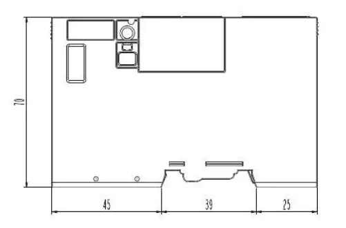
| Module Size | 22mm x 109mm x 70mm |
| Environment Condition | Refer to ‘2. Environment Specification’ |
RIO3 ECAL Wiring Diagram
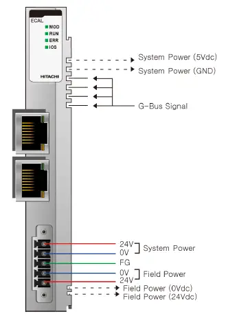
| Pin No. | Signal Description |
| 1 | System Power, 24V |
| 2 | System Power, Ground |
| 3 | Frame Ground |
| 4 | Field Power, Ground |
| 5 | Field Power, 24V |
RIO3 ECAL LED Indicator
LED Indicator
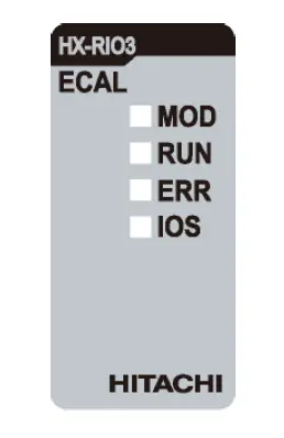
| LED No. | LED Function / Description | LED Color |
| MOD | Module Status | Green/Red |
| RUN | Current Communication Status | Green |
| ERR | Error Status | Red |
| IOS | Expansion I/O Module Status | Green/Red |
MOD (Module Status
| Status | LED | To indicate |
| Not Powered | OFF | power is not supplied to the unit. |
| Normal, Operational | Green | The unit is operating in normal condition. |
| Device in Standby | Flashing Green | The EEPROM parameter is not initialized yet. Serial Number is zero value (0x00000000) |
| Minor Fault | Flashing Red | The unit has occurred recoverable fault in self-testing. – EEPROM checksum fault. |
| Unrecoverable Fault | Red | The unit has occurred unrecoverable fault in self-testing. – Firmware fault |
RUN Current Running Status LED)
| Status | LED | To indicate |
| Init | OFF | State of the Ether CAT State Machine: INIT = Initialization. |
| Pre-Operation | Blinking | State of the Ether CAT State Machine: PREOP = Pre-Operation. |
| Safe-Operation | Single Flash | State of the Ether CAT State Machine: SAFEOP = Safe-Operation. |
| Initialization or Bootstrap | Flashes | State of the Ether CAT State Machine: BOOT = Bootstrap (Update of the coupler firmware) |
| Operational | ON | State of the Ether CAT State Machine: Operational. |
ERR (Error Status LED)
| Status | LED | To indicate |
| No Error | OFF | No Error. |
| Invalid Configuration | Blinking | Invalid Configuration. |
IOS LED(Extension I/O Module Status LE D
| Status | LED | To indicate |
| Not Powered | OFF | Adapter may not be powered. |
| No Expansion Module | Flashing Red | Adapter has no expansion module. |
| Internal Bus Connection, Run Exchanging I/O | Green | Exchanging I/O data. |
|
Expansion Configuration Failed |
Red | One or more expansion module occurred in fault state.
|
RIO3 ECAL Electrical Interface
RJ 45 Socket
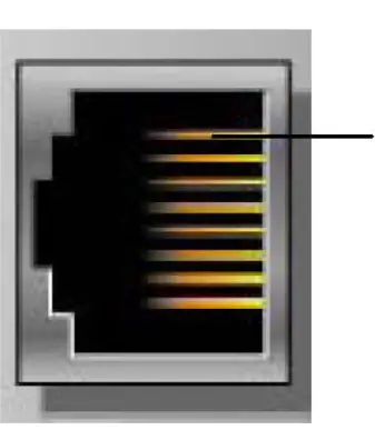
| RJ-45 | Signal Name | Description |
| 1 | TD+ | Transmit + |
| 2 | TD- | Transmit – |
| 3 | RD+ | Receive + |
| 4 | ||
| 5 | ||
| 6 | RD | Receive- |
| 7 | ||
| 8 | ||
| Case | Shield | Shield RJ-45 Socket |
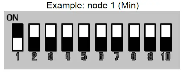
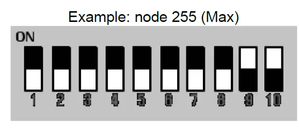
DIP Switch
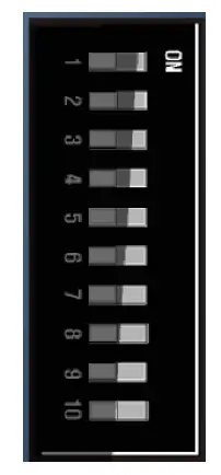
| DIP Pole# | Description |
| 1 | Identification Value DIP bit#0 |
| 2 | Identification Value DIP bit#1 |
| 3 | Identification Value DIP bit#2 |
| 4 | Identification Value DIP bit#3 |
| 5 | IdentificationValue DIP bit#4 |
| 6 | IdentificationValue DIP bit#5 |
| 7 | IdentificationValue DIP bit#6 |
| 8 | IdentificationValue DIP bit#7 |
| 9 | Not Used |
| 10 | Not Used |
EtherCAT ID Type Setup
Hot Connection On TwinCAT
Hot connection function can be used to remove a node from a preconfigured Configurator on or change the
location of nodes and flexible. This feature is available only EtherCAT ID Type in TwinCAT.
The user can use the external Dip Switch settings of the Adapter Identification Value.
For an example of using an external Dip S w itch ( Refer to
Process Image Map
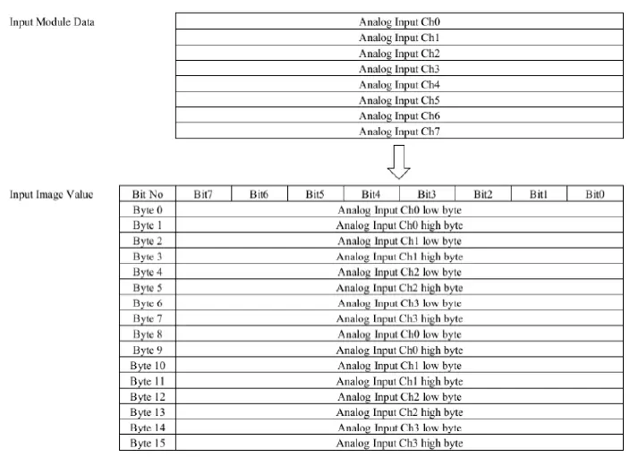
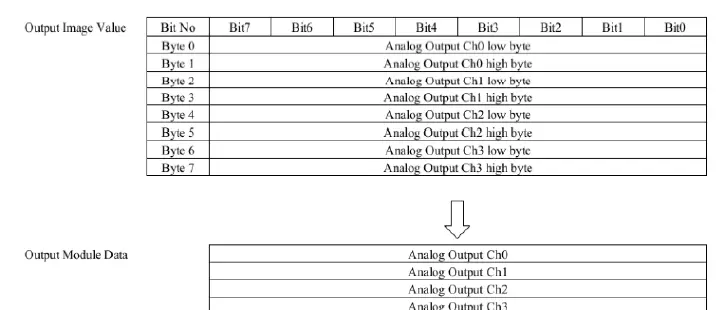
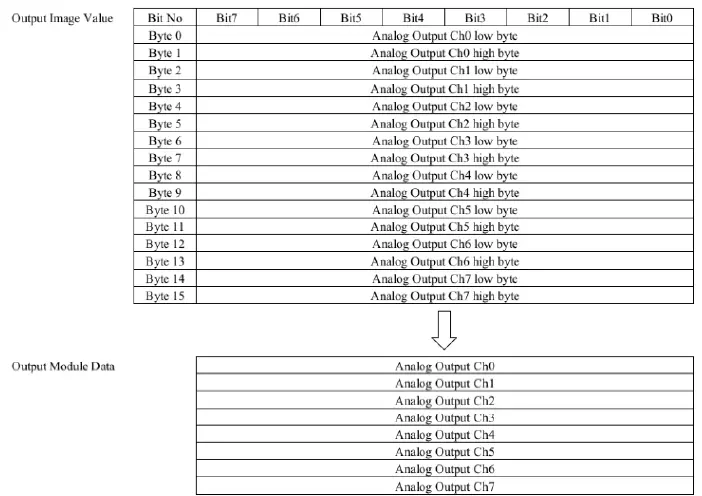
An expansion module may have 3 types of data as I/O data, configuration parameter and memory register. The data exchange between network adapter and expansion modules is done via an I/O process image data by RIO3 Series protocol. The following figure shows the data flow of process image between network adapter and expansion modules.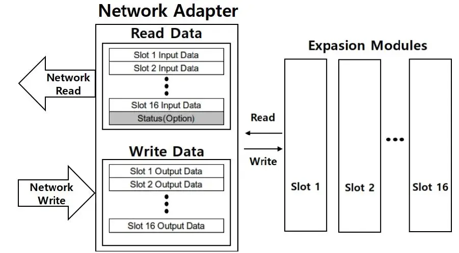
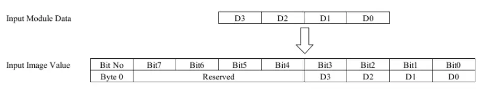
Mapping Data into Image Table
<Discrete Input Module>
- 4 Point Input Module
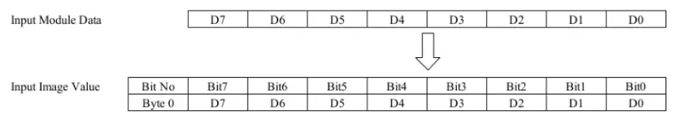
- Point Input Module
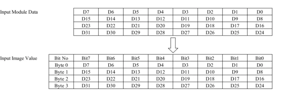
- 32 Point Input Module
Discrete Out put Module
- Point Output Module
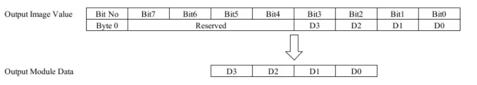
- Point Output Module
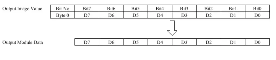
- Point Output Module
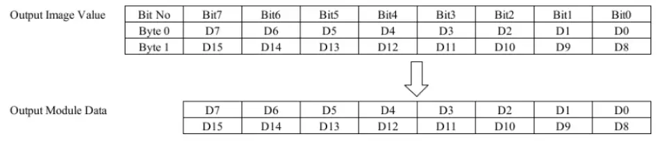
- Point Output Module
Analog Input Module
- Channel Analog Input Module
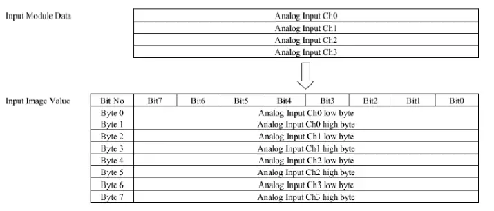
- Channel Analog Input Module
Analog Out put Module
- Channel Analog Out put Module
- Channel Analog Out put Module
Example of Input Process Image (Input Register) Map
Input image data depends on slot position and expansion slot data type. Input process image data is only ordered by expansion slot position.
For example slot configuration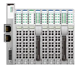
| Slot Address | Module Description |
| #0 | EtherCAT Adapter |
| #1 | 8-discrete input |
| #2 | 8-discrete input |
| #3 | 4-analog input |
| #4 | 16-discrete input |
| #5 | 8-discrete input |
| #6 | 8-discrete input |
| #7 | 8-discrete input |
| #8 | 16-discrete input |
| #9 | 8-discrete input |
- Input Process Image
| Address | b15 | b14 | b13 | b12 | b11 | b10 | b9 | b8 | b7 | b6 | b5 | b4 | b3 | b2 | b1 | b0 |
| 0x0001 | Discrete Input 8 pts (Slot#2) | Discrete Input 8 pts (Slot#1) | ||||||||||||||
| 0x0002 | Analog Input Ch0 high byte (Slot#3) | Analog Input Ch0 low byte (Slot#3) | ||||||||||||||
| 0x0003 | Analog Input Ch1 high byte (Slot#3) | Analog Input Ch1 low byte (Slot#3) | ||||||||||||||
| 0x0004 | Analog Input Ch2 high byte (Slot#3) | Analog Input Ch2 low byte (Slot#3) | ||||||||||||||
| 0x0005 | Analog Input Ch3 high byte (Slot#3) | Analog Input Ch3 low byte (Slot#3) | ||||||||||||||
| 0x0006 | Discrete Input 8 pts (Slot#4) | Discrete Input 8 pts (Slot#4) | ||||||||||||||
| 0x0007 | Discrete Input 8 pts (Slot#6) | Discrete Input 8 pts (Slot#5) | ||||||||||||||
| 0x0008 | Discrete Input 8 pts (Slot#8) | Discrete Input 8 pts (Slot#7) | ||||||||||||||
| 0x0009 | Discrete Input 8 pts (Slot#9) | Discrete Input 8 pts (Slot#8) | ||||||||||||||
3.6.3. Example of Output Process Image (Output Register) Map
Output image data depends on slot position and expansion slot data type. Output process image data is only ordered by expansion slot position.
For example slot configuration
| Slot Address | Module Description |
| #0 | EtherCAT Adapter |
| #1 | 8-discrete output |
| #2 | 8-discrete output |
| #3 | 4-analog output |
| #4 | 4- relay output |
| #5 | 4-relay output |
| #6 | 8-discrete output |
| #7 | 8-discrete output |
| #8 | 4-analog output |
| #9 | 4-relay output |
| #10 | 16-discrete output |
- Output Process Image
| Address | b15 | b14 | b13 | b12 | b11 | b10 | b9 | b8 | b7 | b6 | b5 | b4 | b3 | b2 | b1 | b0 |
| 0x0800 | Discrete Output 8 pts (Slot#2) | Discrete Output 8 pts (Slot#1) | ||||||||||||||
| 0x0801 | Analog Output Ch0 high byte (Slot#3) | Analog Output Ch0 low byte (Slot#3) | ||||||||||||||
| 0x0802 | Analog Output Ch1 high byte (Slot#3) | Analog Output Ch1 low byte (Slot#3) | ||||||||||||||
| 0x0803 | Analog Output Ch2 high byte (Slot#3) | Analog Output Ch2 low byte (Slot#3) | ||||||||||||||
| 0x0804 | Analog Output Ch3 high byte (Slot#3) | Analog Output Ch3 low byte (Slot#3) | ||||||||||||||
| 0x0805 | Empty, Don’t Care | Discrete Out 4 pts (Slot#5) | Empty, Don’t Care | Discrete Out 4 pts (Slot#4) | ||||||||||||
| 0x0806 | Discrete Output low 8 pts (Slot#7) | Discrete Output low 8 pts (Slot#6) | ||||||||||||||
| 0x0807 | Analog Output Ch0 high byte (Slot#8) | Analog Output Ch0 low byte (Slot#8) | ||||||||||||||
| 0x0808 | Analog Output Ch1 high byte (Slot#8) | Analog Output Ch1 low byte (Slot#8) | ||||||||||||||
| 0x0809 | Analog Output Ch2 high byte (Slot#8) | Analog Output Ch2 low byte (Slot#8) | ||||||||||||||
| 0x080A | Analog Output Ch3 high byte (Slot#8) | Analog Output Ch3 low byte (Slot#8) | ||||||||||||||
| 0x080B | Discrete Output low 8 pts (Slot#10) | Empty, Don’t Care | Discrete Out 4 pts (Slot#9) | |||||||||||||
| 0x080C | Empty, Don’t Care | Discrete Output high 8 pts (Slot#10) | ||||||||||||||
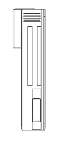
Dimension
RIO3-ECAL
EtherCAT Basics
The EtherCAT protocol uses an officially assigned EtherType inside the Ethernet Frame. The use of this EtherType allows transport of control data directly within the Ethernet frame without redefining the standard Ethernet frame. The frame may consist of several sub-telegrams, each serving a particular memory area of the logical process images that can be up to 4 gigabytes in size. Addressing of the Ethernet terminals can be in any order because the data sequence is independent of the physical order. Broadcast, Multi-cast and communication between slaves are possible.
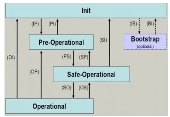
EtherCAT State Machine
The state of the EtherCAT slave is controlled via the EtherCAT State Machine (ESM). Depending upon the state, different functions are accessible or executable in the EtherCAT slave. Specific commands must be sent by the EtherCAT master to the device in each state, particularly during the boot up of the slave.
A distinction is made between the following states:
- Init
- Pre-Operational
- Safe-Operational and
- Operational
- Bootstrap
The regular state of each EtherCAT slave after bootup is the OP state.
Init
After switch-on the EtherCAT slave in the Init state. No mailbox or process data communication is possible. The EtherCAT master initializes sync manager channels 0 and 1 for mailbox communication.
Pre-Operational (Pre-Op)
During the transition between Init and Pre-Op the EtherCAT slave checks whether the mailbox was initialized correctly.
In Pre-Op state mailbox communication is possible, but not process data communication. The EtherCAT master initializes the sync manager channels for process data (from sync manager channel 2), the FMMU channels and, if the slave supports configurable mapping, PDO mapping or the sync manager PDO assignment. In this state the settings for the process data transfer and perhaps terminal-specific parameters that may differ from the default settings are also transferred.
Safe-Operational (Safe-Op)
During transition between Pre-Op and Safe-Op the EtherCAT slave checks whether the sync manager channels for process data communication and, if required, the distributed clocks settings are correct. Before it acknowledges the change of state, the EtherCAT slave copies current input data into the associated DP-RAM areas of the EtherCAT slave controller (ECSC).
In Safe-Op state mailbox and process data communication is possible, although the slave keeps its outputs in a safe state, while the input data are updated cyclically.
Operational (Op)
Before the EtherCAT master switches the EtherCAT slave from Safe-Op to Op it must transfer valid output data.
In the Op state the slave copies the output data of the masters to its outputs. Process data and mailbox communication is possible.
Bootstrap
In the Boot state the slave firmware can be updated. The Boot state can only be reached via the Init state. In the Boot state mailbox communication via the file access over EtherCAT (FoE) protocol is possible, but no other mailbox communication and no process data communication.
CoE Interface
Parameter management in the EtherCAT system
The CiA organization (CAN in Automation) pursues among other things the goal of creating order and exchange ability between devices of the same type by the standardization of device descriptions. For this purpose so-called profiles are defined, which conclusively describe the changeable and unchangeable parameters of a device. Such a parameter encompasses at least the following characteristics:
- Index number – for the unambiguous identification of all parameters. The index number is divided into a main index and a subindex in order to mark and arrange associated parameters.
- Main index
- Subindex, offset by a colon ‘:’
- Official name – in the form of an understandable, self-descriptive text
- Specification of changeability, e.g. whether it can only be read or can also be written
- A value – depending upon the parameter the value can be a text, a number or another parameter index.
Index Range
The relevant ranges for EtherCAT fieldbus users are:
x1000 : This is where fixed identity information for the device is stored, including name, manufacturer,
serial number etc., plus information about the current and available process data configurations. x8000 : This is where the operational and functional parameters for all channels are stored, such as filter settings or output frequency. 4
Other important ranges are:
x4000 : In some EtherCAT devices the channel parameters are stored here
(as an alternative to the x8000 range).
x6000 : Input PDOs (“input” from the perspective of the EtherCAT master) x7000 : Output PDOs (“output” from the perspective of the EtherCAT master)
Communication Objects
| Index | Sub-index | Name | Flags | Default value |
| 1000 | Device type | RO | 0x00001389 | |
| 1001 | Gbus Status | RO | Normal Operation : 0x00 ** | |
| 1002 | Master Fault Action | RW | 0x00 | |
| 1008 | Device name | RO | RIO3-ECAL(HITACHI) | |
| 1009 | Hardware version | RO | RIO3-ECAL.v1 | |
| 100A | Software version | RO | 1.000 | |
|
1018 | Identity | RO | 0x05 | |
| 01 | Vendor ID (HITACHI: 029D) | RO | 0x0000029D | |
| 02 | Product code | RO | 0x474C9086 | |
| 03 | Revision | RO | 0x0001000 | |
| 04* | Serial number | RO | 0xFFFFFFFF | |
| 05 | Release date | RO | 0x20200325 | |
| 10F1 | Error Settings | RO | 0x02 | |
| 01 | Local Error Reaction | RO | 0x00000000 | |
| 02 | Sync Error Counter Limit | RO | 0x00000004 | |
|
1601* | Slot#x, RIO3-xxxx,RXPDO | RO | 0xnn | |
| 01 | SubIndex 001 | RO | 0x7010:01, 8 | |
| … | … | … | … | |
| nn | SubIndex nnn | RO | 0x7010:nn, 8 | |
|
1A01* | Slot#x, GT-xxxx,TXPDO | RO | 0xnn | |
| 01 | SubIndex 001 | RO | 0x6010:01, 8 | |
| … | … | … | … | |
| nn | SubIndex nnn | RO | 0x6010:nn, 8 | |
|
1C00 | Sync manager type | RO | 0x04 | |
| 01 | SubIndex 001 | RO | 0x01 | |
| 02 | SubIndex 002 | RO | 0x02 | |
| 03 | SubIndex 003 | RO | 0x03 | |
| 04 | SubIndex 004 | RO | 0x04 | |
| 1C12 | RxPDO assign | RO | 0x01 | |
| 01 | SubIndex 001 | RO | 0x1601 | |
| 1C13 | TxPDO assign | RO | 0x02 | |
| 01 | SubIndex 001 | RO | 0x1A01 | |
| 02 | SubIndex 002 | RO | 0x1A02 | |
| 7010* | GT-xxxx | RO | 0xnn | |
| 01 | Byte#0 | RW P | 0x00 | |
| … | … | … | … | |
| nn | Byte#nnn | RW P | 0x00 | |
|
8000 | RIO3-ECAL(Parameter) | RO | ||
| 01 | Byte#0 | RW | ||
| 02 | Byte#1 | RW | ||
| 03 | Byte#2 | RW | ||
| 04 | Byte#3 | RW | ||
|
8nn0* | GT-xxxx(Parameter) | RO | ||
| 01 | Byte#0 | RW | ||
| .- | – | – | – | |
| nn | Byte#nnn | RW | ||
| F000 | Module device profile | RO | ||
| 01 | Module index distance | RO | ||
| 02 | Maximum number of modules | RO | ||
|
F010* | Module List | RO | ||
| 01 | Subindex 001 (RIO3-ECAL) | RO | 0x00009086 | |
| – | – | – | ||
| 16 | Subindex 016 | RO | 0x0000xxxx | |
| F050 | Detected Module Ident List | RO | ||
| 01… | SubIndex 001 | RO | ||
- This value can be changed depending on the configuration of expansion modules ** G-BUS Status
- Normal Operation : 0x00
- Communication Fault : 0x02
- Configuration Failed : 0x03
- No Expansion Module : 0x04
- Vendor Error : 0x07
- Not expected slot : 0x08
- CRC Error : 0x09
Troubleshooting
How to diagnose by LED indicator
| LED Status | Cause | Action |
| All LED turns off | – No power |
|
| MOD LED is red |
|
for repair. |
| ERROR LED blinking red |
|
|
| IOS LED turns off |
|
|
| IOS LED flashes red |
| – Add one or more expansion modules. |
|
IOS LED is red | One or more expansion module occurred in fault state.
adapter and expansion module. |
|
| LED Status | Cause | Action |
| All LED turns off | – No power | – Check main power Cable |
| MOD LED is red | – Occurrence critical error in firmware | – Contact Sales team and send module for repair. |
| ERROR LED blinking red | – Invalid Configuration | – Check I/O size configuration |
| IOS LED turns off | – Device may not be powered. | – Check main power Cable |
| IOS LED flashes red | – Adapter has no expansion module | – Add one or more expansion modules. |
|
IOS LED is red | One or more expansion module occurred in fault state. – Detected invalid expansion module ID. – Overflowed Input/Output Size – Too many expansion module – Initialization failure – Communication failure. – Changed expansion module configuration. – Mismatch vendor code between adapter and expansion module. |
– Use expansion slot up to 63. – Compose that IO total size is not excess. – Check status of expansion IO connection. – Check the vendor code of module. |
How to diagnose when device couldn’t communicate network
Inspection of wrong or omission cable connection
- Check status of cable connection for each node.
- Check that all color matches between connector and cable.
- Check wire omission.
Configuration of Node address
- Check duplication node address.
Configuration of Master
- Check configuration of master
- Check whether to do download or don’t
- Check composition is right as below Configuration of communication baud rate I/O size Configuration of each node
Ground and environment
- Check ground is contacted
- Check environment factor (temperature, humidity, etc.) is in less than regular limit
APPENDIX A
Product List
Please refer the separate HX-RIO3 product list document
Glossary
- System Power : The power for starting up CPU.
- Field Power : The power for input and output line.
- EDS : Electronic Data Sheet.
- Sink : The method of in/output power supply if a device has no power source.
- Source : The method of in/output power supply if a device has the power source.


