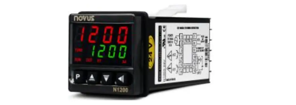
NOVUS N1200 Heater Resistance Fail Detector
 The HBD (Heater Break Detector) option provides means of detecting a mal function in the heater resistance, by monitoring the current that flows through it. This option consists of a dedicated PCB connected internally to the N1200 and a current transformer (CT) mounted externally at the load.
Installation
When the HBD model controller is ordered, the HBD accessory is already mounted in the N1200. The user must then connect the CT to terminals 14 and 15 at the instrument back panel (any polarity).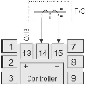 The CT was designed such as to facilitate its insertion in the load circuit. The CT core can be opened to allow the load wire to be installed inside the core, without opening the circuit. The CT wires may be stretched up to 3 meters long and must be kept away from other wires and cables of the installation.
Operation
When the PWM control output is used, the controller monitors the load current when this output is turned ON and OFF, indicting on the kb.i screen the current with higher value (usually, the current that is present when the output is ON.) The minimum current alarm (Kb.L) takes this ON current measurement and compares it with the respective setpont value. If this current is below the alarm set point, the alarm is activated, indicating a faulty resistance. The maximum current (Kb.k) alarm compares OFF current measurement with the setpoint for this alarm. If the current is above the alarm set point, the alarm is activate to indicate problems in the actuator (short-circuited SSR, bad contactor , etc.). For any other situation that does not use the PWM control output, the display current value is the instant value measured. The minimum/maximum current alarm (Kb.Lk) executes both operations described above simultaneously.
Controller configuration
The HBD parameters are:
| Parameter | Function | Cycle |
 | Current indication as measured by the CT (in amperes) | Operation Cycle |
 | Maximum CT Span. For the CT accompanying the controller, this parameter must be defined as 60.0, an indication that the maximum measured current is 60 A | Scale Cycle |
In the alarm Functions parameters, the parameters are:
| Parameter | Function | Cycle | |
 |  | Minimum current alarm. | |
 |  | Maximum current alarm. | Alarm cycle |
 |  | Minimum and maximum current alarm. | |
 | |||
When a HBD alarm functions is used, its alarm setpoint is expressed in Amperes..
| Parameter | Function | Cycle |
 | Electric current values in amperes (A) | Tuning cycle |
Notes:
- For a perfect operation of the controller in monitoring the electric current, the PWM Cycle Time (ct) must be defined with a value above 2 seconds.
- The current measure accuracy is 3.3 % (±2 A).


