
 Porter cable FN250SB FINISH TOOLS User Manual

SAFETY INSTRUCTIONS
The Porter Cable Finish tools are precision-built tools, designed for high-speed, high-volume nailing and stapling. These tools will deliver efficient, dependable service when used correctly and with care. As with any fine power tool, for best performance, the manufacturer’s instructions must be followed. Please study this manual before operating the tool and understand the safety warnings and cautions. The instructions on installation, operation, and maintenance should be read carefully, and the manual kept for reference.
NOTE: Additional safety measures may be required because of your particular application of the tool. Contact your PORTER-CABLE representative or distributor with any questions concerning the tool and its use. PORTER-CABLE, 701 E. Joppa Road, Towson, Maryland 21286, U.S. & Canada Only, E.-U. et Canada seulement.
THREE-YEAR LIMITED WARRANTY
PORTER-CABLE will repair, without charge, any defects due to faulty materials or workmanship for three years from the date of purchase. This warranty does not oo-, er part failure due to normal wear or tool abuse. For further detail on warranty coverage and warranty repair information, visit www.portercable.com or call 1-888-848-5175 (U.S. & Canada Only). This warranty does not apply to accessories or damage caused where repairs have been made or attempted by others. This warranty gives you specific legal rights and you may have other rights in certain states or inches! In addition to the warranty.
1 YEAR OF FREE SERVICE
PORTER-CABLE will maintain the tool and replace worn parts caused by normal use, for free, any time during the first year after purchase.
90-DAY MONEY-BACK GUARANTEE
If you are not completely satisfied with the performance of your PORTER-CABLE Power Tool, Laser, or Nailer for any reason, you can return it within 90 days from the date of purchase with a receipt for a full refund – no questions asked.
LATIN AMERICA
This warranty does not apply to products sold in Latin America. For products sold in Latin America, see the country-specific warranty information contained in the packaging, call the focal company or see the website for warranty information. To register your tool for warranty service visit our website at www.portercable.com.
DEFINITIONS – SAFETY GUIDELINES
When using any pneumatic tool, all safety precautions, as outlined below, should be followed to avoid the risk of death or serious injury. Read and understand the instructions before operating the tool.
WARNING
This manual contains information that is important for you to know and understand. This information relates to protecting YOUR SAFETY and PREVENTING EQUIPMENT PROBLEMS. To help you recognize this information, we use the symbols below. Please read the manual and pay attention to these symbols.
DANGER
Indicates an imminently hazardous situation that, if not avoided, will result in death or serious injury.
WARNING
Indicates a potentially hazardous situation that, if not avoided, may result in minor or moderate injury.
CAUTION
Used without the safety alert symbol indicates a situation that, if not avoided, may result in property damage.
SAFETY INSTRUCTIONS
- EYE PROTECTION which conforms to ANSI specifications and provides protection against flying particles both from the FRONT and SIDE should ALWAYS be worn by the operator and others in the work area when connecting to air supply, loading, operating or servicing this tool. Eye protection is required to guard against flying fasteners and debris, which could cause severe eye injury.
- The employer and/or user must ensure that proper eye protection Is worn. Eye protection equipment must conform to the requirements of the American National Standards Institute, ANSI 287.1/CAN/CSA 294.3, and provide both frontal and side
protection. - NOTE: Non-side shielded spectacles and face shields alone do not provide adequate protection.
- Additional Safety Protection will be required In some environments. For example, the working area may include exposure to noise level which can lead to hearing damage.
- The employer and user must ensure that any necessary hearing protection is provided and used by the operator and others in the work area. Some environments will require the use of head protection equipment. When required, the employer and user must ensure that head protection conforming to ANSI CAN/CSA 289.1 is used.
- Some dust created by power sanding, sawing, grinding, drilling, and other construction activities contain chemicals known to the State of California to cause cancer, birth defects or other reproductive harm. Some examples of these chemicals are:
- lead from lead-based paints
- crystalline silica from bricks and cement and other masonry products
- arsenic and chromium from chemically-treated lumber
- Your risk from these exposures varies, depending on how often you do this type of work. To reduce your exposure to these chemicals: work in a well-ventilated area, and work with approved safety equipment, such as those dust masks that are specially designed to filter out microscopic particles
AIR SUPPLY AND CONNECTIONS
- Do not use oxygen, combustible gases, or bottled gases as a power source for this tool as the tool may explode, possibly causing injury.
- Do not use supply sources that can potentially exceed 200 P.S.I.G. as a tool may burst, the air supply is disconnected.
- If a wrong fitting is us after disconnecting and thus will be able to drive connected possibly causing injury.
- Do not pull the trigger or depress the contact arm while connected to the air supply as the tool may cycle, possibly causing injury.
- Always disconnect air supply: 1.) Before making adjustments; 2.) When servicing the tool;
- When clearing a jam; When the tool is not in use; 5.) When moving to a different work area, accidental actuation may occur, possibly causing injury;
- Before placing the tool on any surface, hanging the tool on the belt, or otherwise temporarily suspending the use of the tool.
LOADING TOOL
When loading the tool Never place a hand or any part of the body in the fastener discharge area of the tool Never point the tool at anyone; 3.) Do not pull the trigger or depress the trip as accidental actuation may occur, possibly causing injury.
OPERATION
Always handle the tool with care Never engage in horseplay Never pull the trigger unless the nose is directed toward the work Keep others a safe distance from the tool while the tool is in operation as accidental actuation may occur, possibly causing injury. The operator must not hold the trigger pulled on contact arm tools except during fastening operation as serious injury could result if the trip accidentally contacted someone or something, causing the tool to cycle. Keep hands and body away from the discharge area of the tool. A contact arm tool may bounce from the recoil of driving a fastener and an unwanted second fastener may be driven possibly causing injury.
Check the operation of the contact arm mechanism frequently. Do not use the tool if the arm is not working correctly as accidental driving of a fastener may result. Do not interfere with the proper operation of the contact arm mechanism. Do not drive fasteners on top of other fasteners or with the tool at an overly steep angle as this may cause deflection of fasteners which could cause injury.
WARNING:! Do not drive fasteners close to the edge of the workpiece as the wood may split, allowing the fastener to be deflected possibly causing injury. This nailer produces SPARKS during operation. NEVER use the nailer near flammable substances, gases or vapors including lacquer, paint, benzine, thinner, gasoline, adhesives, mastics, glues, or any other material that is – or the vapors, fumes or byproducts of which are – flammable, combustible or explosive. Using the nailer in any such environment could cause an EXPLOSION resulting in personal injury or death to the user and bystanders.
MAINTAINING THE TOOL
WARNING
When working on air tools note the warnings in this manual and use extra care when evaluating problem tools.
TOOL SPECIFICATIONS

FASTENER SPECIFICATIONS
TOOL AIR FITTING
These tools use a free-flow to lug, 1/4 N.P.T. The in§ide diameter should be.200″ (5mm) or larger. The fitting u banof5har, in air pressure, when disconnected from the air supply.
OPERATING PRESSURE
70 to 100 psi (4.8 to 6.9 bar). Select the operating pressure within this range for the best fastener performance.
WARNING
DO NOT EXCEED THIS RECOMMENDED OPERATING PRESSURE
SEQUENTIAL TRIP
This tool is supplied with a sequential trip trigger installed.
WEIGHT
- 2.69 lbs.
- 4.03 lbs.
The Sequential Trip requires the operator to hold the tool against the work before pulling the trigger. This makes accurate fastener placement easier, for instance on trim installation, toe nailing, and crating applications. The Sequential Trip allows exact fastener location without the possibility of driving a second fastener on recoil. The Sequential Trip Tool has a positive safety advantage because it will not accidentally drive a fastener if the tool is contacted against the work – or anything else – while the operator is holding the trigger pulled.
AIR SUPPLY AND CONNECTIONS
WARNING
Do not use oxygen, combustible gases, or bottled gases as a power source for this tool as a tool may explode, possibly causing injury.
FITTINGS
Install a male plug on the tool which is free flowing and which will release air pressure from the tool when disconnected from the supply source.
HOSES: Air hoses should have a minimum of 150 p.s.i. (10.6 kg/cm2 working pressure rating or 150 percent of the maximum pressure that could be produced in the air system. The supply hose should contain a fitting that will provide “quick disconnecting” from the male plug on the tool.
SUPPLY SOURCE
Use only clean regulated compressed air as a power source for this tool.
NEVER USE OXYGEN, COMBUSTIBLE GASES, OR BOTTLED GASES, AS A POWER SOURCE FOR THIS TOOL AS THE TOOL MAY EXPLODE THE REGULATOR
A pressure regulator with an operating pressure of O – 125 p.s.i. (0 – 8.79 KG/CM) is required to control the operating pressure for the safe operation of this tool. Do not connect this tool to air pressure which can potentially exceed 200 p.s.i. (14 KG/CM2)as a tool may fracture or burst, possibly causing injury.
OPERATING PRESSURE
Do not exceed recommended maximum operating pressure as tool wear will be greatly increased. Their supply must be capable of maintaining the operating pressure at the tool. Pressure drops in the air supply can reduce the tool’s driving power. Refer to “TOOL
SPECIFICATIONS” for setting the correct operating pressure for the tool.
FILTER
Dirt and water in the air supply are major causes of wear in pneumatic tools. A filter will help to get the best performance and minimum wear from the tool. The filter must have adequate flow capacity for the specific installation. The filter has to be kept clean to be effective in providing clean compressed air to
the tool. Consult the manufacturer’s instructions on proper maintenance of your filter. A dirty and clogged filter will cause a pressure drop which will reduce the tool’s performance.
LUBRICATION
Frequent, but not excessive, lubrication is required for best performance. Oil added through the airline connection will lubricate the internal parts. Use PORTER-CABLE Air Tool Lubricant, Mobil Velocite #10, or equivalent. Do not use detergent oil or additives as these lubricants will cause accelerated wear to the seals and bumpers in the tool, resulting in poor tool performance and frequent tool maintenance. If no airline lubricator is used, add oil during use into the air fitting on the tool once or twice a day. Only a few drops of oil at a time is necessary. Too much oil will only collect inside the tool and will be noticeable in the exhaust cycle.
COLD WEATHER OPERATIONS
When operating tools at a temperature
- Make sure compressor tanks
- Keep the tool as warm as possible prior to using it.
- Make certain all fasteners have been removed from a magazine.
- Lower air pressure to 80 psi or less.
- Reconnect the air and load nails into the magazine.
- Actuate the tool 5 or 6 times into scrap lumber to lubricate o-rings.
- Turn the pressure up to the operating level (not to exceed 120 psi) and use the tool as normal.
- Always drain the compressor tanks at least once a day.
CAUTION
Do not store tools in a cold weather environment to prevent frost or ice formation on the tools operating valves and mechanisms that could cause tool failure.
CAUTION
Some commercial airline drying liquids are harmful to “O”-rings and seals – do not use these low-temperature air dryers without checking the compatibility
LOADING THE BN200SB
WARNING
EYE PROTECTION which conforms to ANSI specifications and provides protection against flying particles both from the FRONT and SIDE should ALWAYS be worn by the operator and others in the work area when loading, operating or servicing this tool. Eye protection is required to guard against flying fasteners and debris, which could cause severe eye injury.
WARNING
The employer and/or user must ensure that proper eye protection is worn. Eye protection equipment must conform to the requirements of the American National Standards Institute, ANSI Z87.1/CAN/CSA Z94.3, and provide both frontal and side
protection.
NOTE
Non-side shielded spectacles and face shields alone do not provide adequate protection.
TO PREVENT ACCIDENTAL INJURIES
- Never place a hand or any other part of the body In the nail discharge area of the tool while the air supply is connected.
- Never point the tool at anyone else.
- Never engage in horseplay.
- Never pull the trigger unless the nose is directed at the work.
- Always handle the tool with care.
- Do not pull the trigger or depress the trip mechanism while loading the tool.

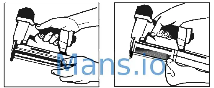
- Disengage the latch and pull back the magazine side.
- With the magazine fully open insert fasteners. Points must be against the bottom of the magazine.

- Push magazine forward
- Continue pushing until the latch is engaged.
LOADING THE FN250SB
WARNING
EVE PROTECTION which conforms to ANSI specifications and provides protection against flying particles both from the FRONT and SIDE should ALWAYS be worn by the operator and others in the work area when loading, operating, or servicing this tool. Eye protection is required to guard against flying fasteners and debris, which could cause severe eye Injury. The employer and/or user must ensure that proper eye protection is worn. Eye protection equipment must conform to the requirements of the American National Standards Institute, ANSI 287.1/CAN/CSA 294.3, and provide both frontal and side protection. NOTE: Non-side shielded spectacles and face shields alone do not provide adequate protection.
WARNING·I TO PREVENT ACCIDENTAL INJURIES
- Never place a hand or any other part of the body in the nail discharge area of the tool while the air supply is connected.
- Never point the tool at anyone else.
- Never engage in horseplay.
- Never pull the trigger unless the nose is directed at the work.
- Always handle the tool with care.
- Do not pull the trigger or depress the trip mechanism while loading the tool.
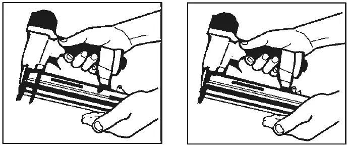
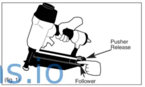
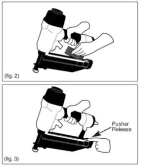
- LOAD NAILS
Pull the follower back until it latches. (fig. 1)
- Press pusher release to disengage the follower (fig. 3)

TOOL OPERATION
!WARNING
EYE PROTECTION which conforms to ANSI specifications and provides protection against flying particles both from the FRONT and SIDE should ALWAYS be worn by the operator and others in the work area when connecting to air supply, loading, operating or servicing this tool. Eye protection is required to guard against flying fasteners and debris, which could cause severe eye injury. The employer and/or user must ensure that proper eye protection is worn. Eye protection equipment must conform to the requirements of the American National Standards Institute, ANSI 287.1/CAN/CSA 294.3, and provide both frontal and side protection.
NOTE
Non-side shielded spectacles and face shields alone do not provide adequate protection.
BEFORE HANPUNG OR OPERATING THIS TOOL
- READ AND UNDERSTAND THE WARNINGS CONTAINED IN THIS MANUAL.
- REFER TO “TOOL SPECIFICATIONS” IN THIS MANUAL TO IDENTIFY THE OPERATING SYSTEM ON YOUR TOOL.
SEQUENTIAL TRIP OPERATION
This tool is supplied with a sequential trip trigger installed. The SEQUENTIAL TRIP contains a contact trip that operates in conjunction with the trigger to drive a fastener. To operate a sequential trip tool, first, position the contact trip on the work surface
WITHOUT PULLING THE TRIGGER
Depress the contact trip and then pull the trigger to drive a fastener. As long as the contact trip is contacting the work and is held depressed, the tool will drive a fastener each time the trigger is depressed. If the contact trip is allowed to leave the work surface, the sequence described above must be repeated to drive another fastener.
SEQUENTIAL TRIP OPERATION
Press the contact trip against the work surface, without touching the trigger.
THE TOOL MUST NOT CYCLE
Hold the tool off the work surface and pull the trigger.
THE TOOL MUST NOT CYCLE
Release the trigger. The trigger must return to the trigger stop on the frame. Pull the trigger and press the contact trip against the work surface.
THE TOOL MUST NOT CYCLE
With your finger off the trigger, press the contact trip against the work surface. Pull the trigger.
THE TOOL MUST CYCLE
IN ADDITION TO THE OTHER WARNINGS CONTAINED IN THIS MANUAL OBSERVE THE FOLLOWING FOR SAFE OPERATION
- Use the PORTER-CABLE pneumatic tool only for the purpose for which it was designed.
- Never use this tool in a manner that could cause a fastener to be directed toward the user or others in the work area.
- Do not use the tool as a hammer.
- Always carry the tool by the handle. Never carry the tool by the air hose.
- Do not alter or modify this tool from the original design or function without approval from PORTER-CABLE, INC.
- Always be aware that misuse and improper handling of this tool can cause injury to yourself and others.
- Never clamp or tape the trigger or contact trip in an actuated position.
- Never leave a tool unattended with the air hose attached.
- Do not operate this tool if it does not contain a legible WARNING LABEL.
- Do not continue to use a tool that leaks air or does not function properly.
- Notify your nearest Porter cable representative if your tool continues to experience functional problems.
MAINTAINING THE PNEUMATIC TOOL
When Working on air tools, note the warnings in this manual and use extra care evaluating problem tools.
CAUTION
Pusher spring (constant force spring). Caution must be used when working with the spring assembly. The spring is wrapped around, but not attached to, a roller. If the spring is extended beyond its length, the end will come off the roller and the spring will roll up with a snap, with a chance of pinching your hand. Also, the edges of the spring are very thin and could be cut. Care must also be taken to insure no permanent kinks are put in the spring as this will reduce the spring’s force.
REPLACEMENT PARTS
PORTER-CABLE replacement parts are recommended. Do not use modified parts or parts which will not give equivalent performance to the original equipment.
ASSEMBLY PROCEDURE FOR SEALS
When repairing a tool, make sure the internal parts are clean and lubricated. Use Parker “O”-LUBE or equivalent on all “O”-rings. Coat each “O”-ring with “O”-LUBE before assembling. Use a small amount of oil on all moving surfaces and pivots. After reassembly add a few drops of
PORTER-CABLE
Air Tool Lubricant through the air line fitting before testing.
AIR SUPPLY-PRESSURE
Air volume is as important as ai stock to the tool but may be inadequate because of undersized fittings and water in the system. Restricted air flow will prevent the tool from receiving an adequate volume of air, even though the pressure reading is high. The results will be a slow operation, misfeeds, or reduced driving power. Before evaluating tool problems for these symptoms, trace the air supply from the tool to the supply source for restrictive connectors, swivel fittings, low points containing water, and anything else that would prevent the full volume flow of air to the tool.
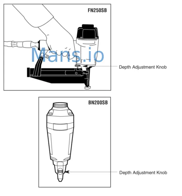
DEPTH ADJUSTMENT
Warning: Always disconnect the air supply: Before making adjustments when servicing the tool; When clearing a jam; When the tool is not in use; or When moving to a different work area, as accidental actuation may occur, possibly causing injury.
BN200SB AND FN250SB FASTENER CONTROL ADJUSTMENT
The Fastener Control adjustment feature provides close control of the fastener drive depth; from flush with the work surface to shallow or deep countersink. First, set the air pressure for a consistent drive in the specific work. Then use the Fastener Control adjustment to give the desired depth of drive.
TO ADJUST FASTENER CONTROL ADJUSTMENT
- With an air pressure set, drive a few fasteners into a representative material sample to determine if an adjustment is necessary.
- If adjustment is required, disconnect the air supply.

TROUBLESHOOTING
- PROBLEM CAUSE CORRECTION
- Trigger valve housing leaks air ____ ring cut or cracked . .. . .. . .. . .. . .. Replace
- Trigger valve stem leaks air ring/seals cut or cracked . . .. . .. . .. Replace trigger valve assembly
- Frame/nose leaks air·———-nose screws . . . . . .. Tighten and recheck
- 0-ring or Gasket is cut or cracked .. . .. Replace O·ring or gasket
- Bumper cracl<edlworn .. . .. . .. . .. . .. Replace bumper
- Frame/cap leaks ——–Damaged gasket or seal . .. . .. . .. . .. Replace gasket or seal
- Cracked/worn head valve bumper .. . .. Replace bumper
- Loose cap screws .. . .. . .. . .. . .. . .. Tighten and recheck
- Failure to cycle-····················································—Air supply restriction . .. . .. . .. . .. . .. Check air supply equipment
- Tool dry, lack of lubrication . . .. . .. . .. Use PORTER-CABLE Air Tool Lubricant
- Worn head valve O-rings . .. . .. . .. . .. Replace O-rings
- Broken cylinder cap spring . . .. Replace cylinder cap spring
- Head valve slucl< in cap . . . . . .. Disassemble/Checl</Lubricate
- Lac,k of power; slow to cycle ______ Tool dry, lacks lubrication . .. . .. . .. . .. Use PORTER-CABLE Air Tool Lubricant
- Broken cylinder cap spring . . .. . .. . .. Replace cap spring
- ().rings/seals cut or cracked . .. . .. . .. Replace O•ringslseals
- Exhaust blocked . .. . .. . .. . .. . .. . .. Check bumper. head valve spring, muffler
- Trigger assembly worn/leaks . .. . .. . .. Replace trigger assembly
- Dirt/tar build up on driver . .. . .. . .. . .. Disassemble nose/driver to clean
- The cylinder sleeve is not seated correctly on the bottom bumper
- Head valve dry . .. . . . .. Disassemble to correct . .. . .. . .. Disassemble/lubricate
- Air pressure too low . . .. . .. . .. . .. . .. Check air supply equipment
- Skipping fasteners; Intermittent feed – –Worn bumper . . .. . .. . .. . .. . .. Replace bumper
- Tar/dirt in driver channel . .. . .. . .. . . . Disassemble and clean nose and driver
- Air restriction/inadequate air flow through
- quick disconnect socket and plug .. . .. Replace quid< disconnect fittings
- Worn piston ().ring . . .. . .. . .. . .. . .. Replace O-ring, check driver
- Tool dry, lacks lubrication . .. . Use PORTER-CABLE Air Tool Lubricant
- MDamta~edt p::Eher slprsing. system lo tool . . . · then all screws . . . . . . se only recommended listeners
- Bent fasteners . .. .. . .. . .. . .. . .. . . . Discontinue using these fasteners
- Wrong size fasteners . .. . .. . .. . .. . .. Use only recommended fasteners
- Leaking head cap gasket . .. . .. . .. . .. Tighten screws/replace gasket
- Trigger valve O-ring cul/worn . .. . .. . .. Replace O-ring
- Broken/chipped driver .. . .. . .. . .. . .. Replace driver (check piston O-ring)
- Dry/dirty magazine . . . . .. . .. Clean/lubricate use PO
- Worn magazine . . .. . .. . .. . .. . .. . .. Replace magazine
- Fasteners Jam In tool———Uriver channel worn . . .. . .. . .. . .. . .. Replace nose/check door
- Wrong size fasteners . .. . .. . .. . .. . . . Use only recommended fasteners
- Bent listeners . .. .. . .. . .. . .. . .. . .. Discontinue using these fasteners
- Loose magazine/nose screws .. . .. . .. Tighten all screws
- Broken/chipped driver .. . .. . .. . .. . .. Replace driver


 Drill Instruction Manual")


 Variable Speed Bench Jointer Instruction Manual")


 Hammer Drill/drill Driver Instruction Manual")


