 Security Keypad Z-WaveTM 700
Quick Start Guide_ V1.0
Model: 7BA-KP-V-B-C0
Safety Information
 WARNING: Any battery may leak harmful chemicals which may damage skin, clothing or the inside of the device.
TO AVOID THE RISK OF INJURY, DO NOT LET ANY MATERIAL LEAKED FROM A BATTERY COME IN CONTACT WITH EYES OR SKIN. Any battery may rupture or explode if put in a fire or otherwise exposed to excessive heat.
TO AVOID THE RISK OF INJURY, DO NOT EXPOSE BATTERIES TO EXCESSIVE HEAT.
To reduce the risk of personal injury or harm to your device, take the following precautions:
![]() Do not use different brands of batteries in the same device
Do not use different brands of batteries in the same device![]() When replacing batteries always replace the whole set
When replacing batteries always replace the whole set![]() Do not use rechargeable or reusable batteries
Do not use rechargeable or reusable batteries![]() Do not allow children to install batteries unsupervised
Do not allow children to install batteries unsupervised![]() Follow battery manufacturer’s instructions as to proper handling, storage, and disposal of batteries.
Follow battery manufacturer’s instructions as to proper handling, storage, and disposal of batteries.
CAUTION: Risk of fire or explosion if the battery is replaced by an incorrect type
![]() IMPORTANT: Do not expose yourself to rain. This product contains small parts and is not suitable for children. Periodically check the condition of the batteries.
IMPORTANT: Do not expose yourself to rain. This product contains small parts and is not suitable for children. Periodically check the condition of the batteries.
![]() CAUTION: Correct Disposal of this product. This marking indicates that this product should not be disposed of with other household wastes. To prevent possible harm to the environment or human health from uncontrolled waste disposal, recycle it responsibly to promote the sustainable reuse of material resources. To return your used device, please use the return and collection systems or contact the retailer where the product was purchased. They can take this product for environmentally safe recycling.
CAUTION: Correct Disposal of this product. This marking indicates that this product should not be disposed of with other household wastes. To prevent possible harm to the environment or human health from uncontrolled waste disposal, recycle it responsibly to promote the sustainable reuse of material resources. To return your used device, please use the return and collection systems or contact the retailer where the product was purchased. They can take this product for environmentally safe recycling.
PACKAGE CONTENTS
- Keypad*1

- CR123A batteries *2 (pre-installed)

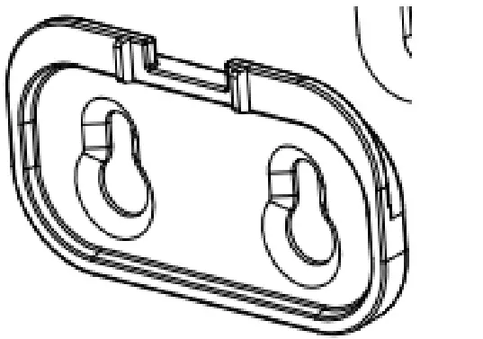
- Bracket *1

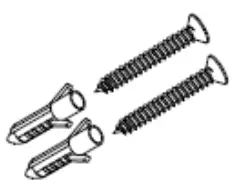
- Installation kit
(a) screw*2, wall anchor*2
(b) double-sided adhesive tape*1
(c) reset pin *1
- Quick start guide*1


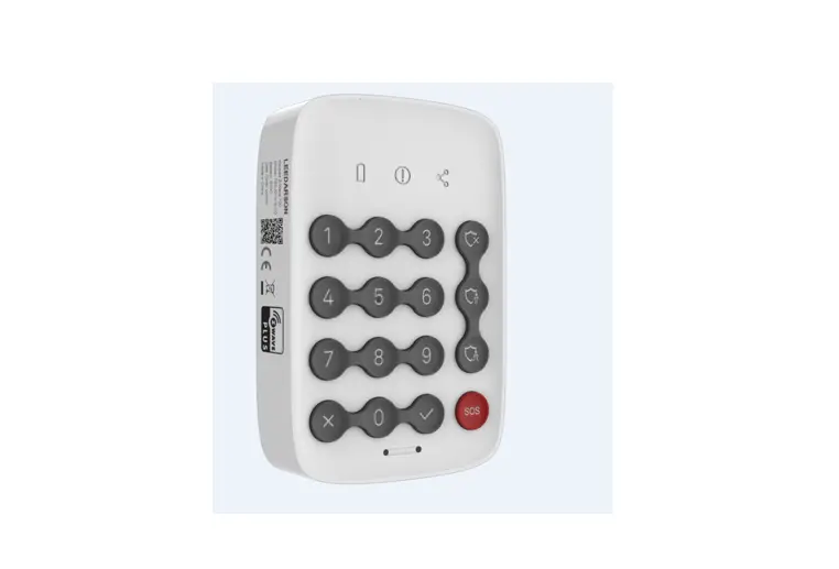
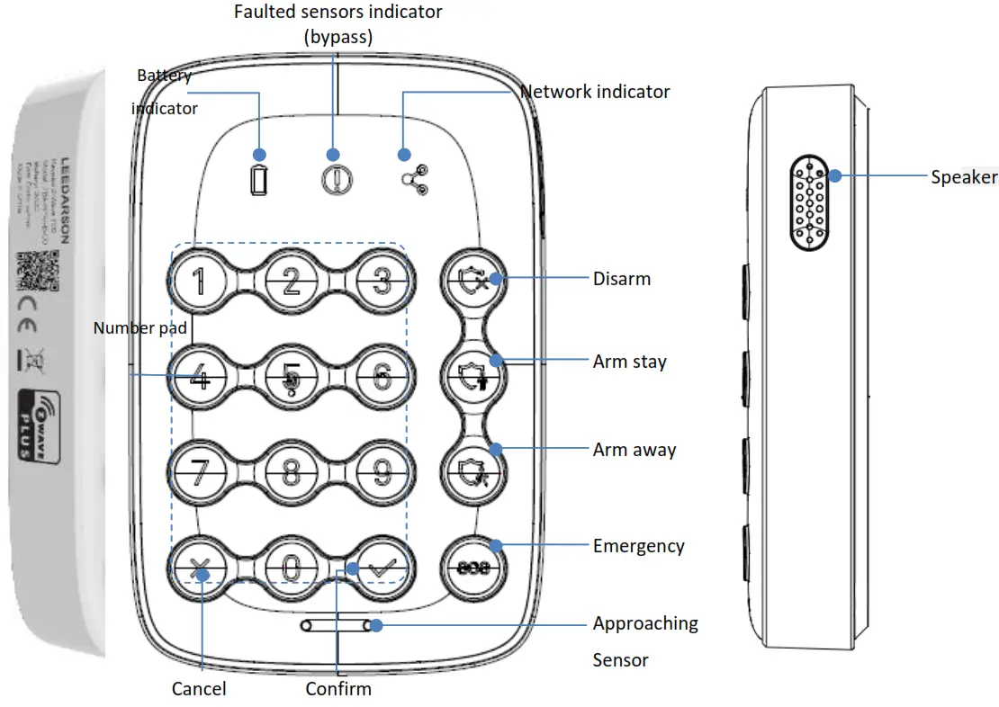
Product Description
The keypad provides a convenient user interface to arm or disarm the system with a PIN code.
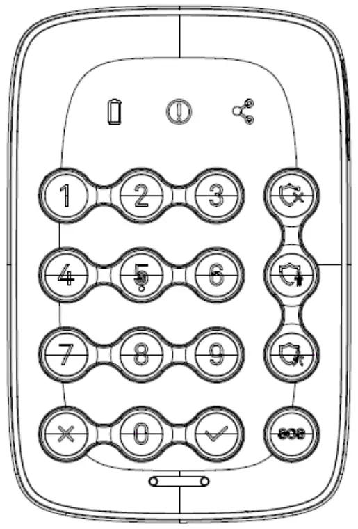
Components
| Indicator symbol | Status Description |
 | Battery capacity:
|
 | There are one or more faulted sensors when arming the system. |
 | Network connection:
|
Functions of actions
| Trigger | Description |
| Power on | In the network: Indicator LED and backlight will ON for 2 seconds after device power on. Buzzer beeps 1 time. (LED light on sequence: First network/battery/ faulted sensor Indicator LED light on red and turn to green, then disarm(green)/arm stay(blue)/arm away(blue) /SOS (red) LED on, finally 0~9+confirm/delete white backlight on, totally it takes about 2 seconds after device power on. The buzzer long beeps 1 time.) Not in the network: Indicator LED and backlight will ON for 2 seconds after device power on. Buzzer beeps 1 time. (LED light on sequence: First network/battery/ faulted sensor Indicator LED light on red and turn to green, then disarm(green)/arm stay(blue)/arm away(blue) /SOS (red) LED on, finally 0~9+confirm/delete white backlight on,totally it takes about 2 seconds after device power on. The buzzer long beeps 1 time.) |
| SmartStart Inclusion | Add the Keypad into the Z-Wave network via SmartStart: 1. Add Keypad DSK into the primary controller SmartStart Provisioning List (If you don’t know how to do this, refer to its manual). 2. Power on the Keypad again. 3. The Keypad will send the “Z-Wave protocol Command Class” frame to start SmartStart Inclusion. 4. Network green LED will flash at every 1 second to indicate that the inclusion is working, and solid green LED 3 seconds for indicating the inclusion is successful, otherwise, the LED will be solid yellow in which you need to repeat the process from step 2 Note: Keypad will reset itself to factory default by sending “Device Reset Locally CC” when it is included in a non-security Z- Wave network. DSK QR code is on the left side of the product with laser printing. Users should follow the procedure in the section below if the controller does not support SmartStart inclusion. |
| Short press pair button three-time | Add the Keypad into the Z-Wave network: 1. Set the Z-Wave network main controller into learning mode (see Z-Wave network controller operating manual). 2. Trigger this action. 3. Network green LED will flash at every 1 second to indicate that the inclusion is working, and solid green LED 3 seconds for indicating the inclusion is successful, otherwise, the LED will be solid yellow in which you need to repeat the process from step 2. Remove the Keypad from a Z-Wave network: 1. Set the Z-Wave network main controller into removing mode (see Z-Wave controller operating manual). 2. Trigger this button action. the Network LED will flash at every 1 second.3. If the removal is successful, the LED will solid green for 3 seconds. If the removing is failed then the LED displays yellow for 3 seconds, otherwise, you need to repeat the process from step 2. Note: Keypad will start SmartStart Inclusion when it is removed from a ZWave network. |
| Press the pair button and hold more than 5 seconds | Network Indicator green LED will fast blinking and backlight will ON for 2 seconds. Buzzer beeps 1 time after resetting successfully. Reset the Keypad to factory default. 1. Device will reset itself to factory default by sending a “Device Reset Locally Notification” to the gateway. 2. If triggered the factory reset, the network connection led will solid green while the factory reset is completed. Note: Please use this procedure only when the network primary controller is missing or otherwise inoperable. |
| Disarm | Solid green: Press correct pin code then press disarm button, disarm mode successfully, Buzzer will short beep 2 times in 1 second.(Beep/beep) If disarm fails, e.g. incorrect PIN code. Disarm button LED will no reaction and buzzer will have multiple beeps: long beep one time, short beep twice in 1.5 seconds. (Beep~/Beep beep) |
| Arm Away | Blinking blue: Press correct pin code then press arm away button, exit delay ongoing, buzzer beeps 10 seconds(Count down default is 10 seconds, user can set count down timing by APP. Meanwhile, the gateway could also have beeps 10 seconds.)
|
| Arm Stay | Blinking blue: Press correct pin code then press arm stay button, exit delay ongoing (Count down default is 10 seconds, user can set count down timing by APP. Meanwhile, the gateway could also have beeps for 10 seconds.) Arm Stay But to save keypad power if the user set count time is 30 seconds, the keypad will max beep 10 seconds, and gateway will beep 30 seconds. Solid blue: Arm stay successful, Internet indicator is ON after summit arm stays. The buzzer will long beep 1 time in 1 second.(Beep~) If the arm stays fails, e.g. incorrect PIN code. Arm Stay LED button will OFF and the buzzer will have multiple beeps: long beep one time, short beep twice in 1.5 seconds. (Beep~/Beep beep) |
| SOS | Blinking red: Press SOS button for 3 seconds, SOS button blinking in red. Solid red: SOS successfully sent, SOS button will solid in red. The buzzer long beeps 1 time. If fail with communication, SOS button will OFF and buzzer will have multiple SOS beeps: long beep one time, short beep twice in 1.5 seconds. (Beep~/Beep beep) SOS is not a mode key but a behavior key and SOS disarm will be done by Gateway. |
| Entry Delay | Entry delay is activated, buzzer will beep 10 seconds (Count down default is 10 seconds, user can set count down timing by APP. Meanwhile gateway could also have beeps 10 seconds.) Entry Delay But to save keypad power, if the user set count time is 30 seconds, the keypad will max beep 10 seconds, and gateway will beep 30 seconds. |
| Exit Delay | Exit delay is activated, buzzer will beep 10 seconds Count down default is 10 seconds, user can set count down timing by APP. Meanwhile gateway could also have beeps 10 seconds.) Exit Delay But to save keypad power, if the user set count time is 30 seconds, the keypad will max beep 10 seconds, and gateway will beep 30 seconds. |
| Network Indicator | Network indicator: Slow flashing green: Pairing or sending data Fast flashing green: About to reset No or bad signal of the hub: Solid Yellow. Paired to the hub and good signal: Solid green |
| Battery Indicator | Battery capacity: When the approaching sensor is activated, the battery icon shows Green indicates the battery capacity is more than 10%, When the approaching sensor is activated, the battery icon shows solid yellow indicate the battery capacity is around 10%~15%. When the approaching sensor is activated, the battery icon shows blinking yellow indicate the battery capacity is below 10%.(10% means user could use keypad about one week ) |
| Faulted Sensor Indicator | Solid yellow: There are one or more faulted sensors when arming the system, meaning some door or window is not closed properly. Buzzer will have multiple beeps: long beep one time, short beep twice in 1.5 seconds. (Beep~/Beep beep) User can press the password + √ to bypass the faulted sensor indicator. |
| approachin g sensor is triggered | In the network: If trigger the approaching sensor, the battery/network indicator LED on, Only the present mode backlight will on 5 seconds(for example, if the present mode is disarmed mode, the disarm green backlight will solid for 5 seconds, others no LED behavior), 0~9/check/select keys no behavior. Buzzer beeps one time. Fail to connect to the network: NOP |
| Tamper switch is triggered | In the network: Send Notification report, and Buzzer beeps 1 times. Not in the network: A notification report will be sent after the next network access. |
This product can be operated in any Z-Wave network with other Z-Wave certified devices from other manufacturers. All mains operated nodes within the network will act as repeaters regardless of vendor to increase the reliability of the network.
Functions
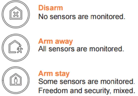
After the installation, you can easily control the system using the keypad.![]() Arm stay/Arm away/Disarm the system by press the mode button followed by your PIN-code and press the confirm
Arm stay/Arm away/Disarm the system by press the mode button followed by your PIN-code and press the confirm
![]() button. The PIN code is consisted of 6 digits and can be modified in the App.
button. The PIN code is consisted of 6 digits and can be modified in the App.
![]() Press the Emergency button and hold for 3 seconds and release to send a panic signal.
Press the Emergency button and hold for 3 seconds and release to send a panic signal.

Deactivate an emergency event by pressing the disarm button followed by your PIN code.
![]() Faulted sensor:
Faulted sensor:
If there is a faulted sensor when arming the system, you will need to press the confirm (√) button again to “force arm” the system.
![]() Firmware upgrade:
Firmware upgrade:
When there is a new version of firmware for the device available, you will get a notification in the App. Then you can decide whether to upgrade.
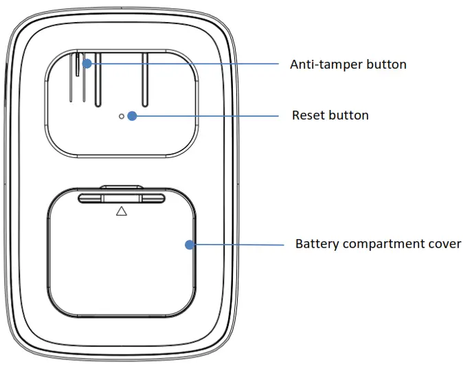
![]() Anti-tamper alarm:
Anti-tamper alarm:
After the keypad is paired to a hub and installed on a bracket, the anti-tamper button will be pressed down. Once it is taken off the bracket the anti-tamper alarm will be triggered after the countdown. Perform the disarm action to stop the countdown.![]() Reset or manual pairing:
Reset or manual pairing:
If you need to manually pair the keypad with the hub, or reset the keypad, just press the reset button on the back with the reset pin(comes in the package), hold for 3 seconds, and release. The keypad will clear all the network information and reboot, and all the LED will be on for a moment with 2 beeps. Then the reset is done. After reset, it will start to search and join the hub again.
Mount the keypad on the wall
Prior to installing on the wall, please perform an arming and disarming operation at the location where you decide to mount the keypad, to make sure the wireless signal is good. The mounting location should be somewhat near the door you usually use to enter or exit the home.
Do not install the Keypad:
1. outside the premises (outdoors).
2. near the metal objects and mirrors that cause radio signal attenuation or shading it.
3. near the powerful main wiring.
Installation:
Step 1: Fix the bracket to the wall either by
A. Screws
B. Double-sided adhesive tape for different surfaces.
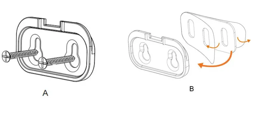 If you use adhesive tape, please clean the mounting surface with a suitable degreaser agent. Please note that some surfaces may be unsuitable for mounting using adhesive tape.
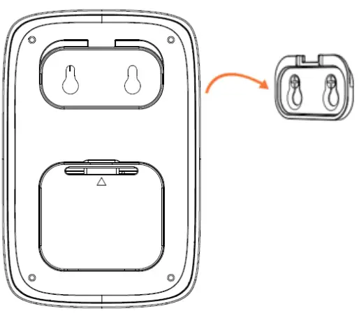
Step 2: Hang the keypad on the bracket.
 Changing the Batteries
 Changing the Batteries
When the battery is low the battery LED will be red and you will receive a notification in your App to remind you the battery change. Please do as follows:
Step 1: Disarm the system, and remove the keypad from the bracket.
Step 2: Because the tamper switch is triggered, you will need to disarm the system to stop the countdown.
Step 3: Open the battery compartment cover and remove the old batteries and replace with new CR123A batteries.
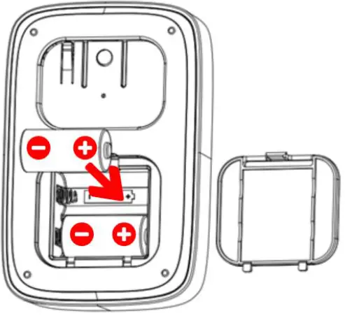 Step 4: Hang the keypad back on the bracket.
Troubleshooting
The keypad is not working and the indicator is not lit
Make sure the batteries are installed correctly and full of power.
If you have done the previous checking and it is still not responding please change a new pair of batteries or try to reset the keypad.
Caution:
This device complies with Part 15 of the FCC rules. Operation is subject to the following two conditions: (1) this device may not cause harmful interference, and (2) this device must accept any interference received, including interference that may cause undesired operation. Changes or modifications not expressly approved by the party responsible for compliance could void the user’s authority to operate the equipment.
Hereby, Corporation declares that this device is in compliance with the essential requirements and other relevant provisions of Directive 2014/53/EU
Special Rule Of Each Command Class
Z-Wave Plus™ Info Report Command Class
| Parameter | Value |
| Z-Wave Plus Version | 0×02 |
| Role Type | 0×07 (ZWAVEPLUS_INFO_REPORT_ROLE_TYPE_SLAVE_SLEEPING_LISTENING) |
| Node Type | 0×00 (ZWAVEPLUS_INFO_REPORT_NODE_TYPE_ZWAVEPLUS_NODE) |
| Installer Icon Type | 0×2001 (ICON_TYPE_SPECIFIC_ENTRY_CONTROL_KEYPAD_0_9) |
| User Icon Type | 0×2001 (ICON_TYPE_SPECIFIC_ENTRY_CONTROL_KEYPAD_0_9) |
Association Command Class
Motion Sensor supports 1 association group and max 5 nodes for each group.
Association Group Info Command Class
Association Group Info
| Grouping identifier | Group Name | Profile MS | Profile LS |
| 1 | Lifeline | 0×00 | 0×01 |
Association Group Command-List
| Group 1 | Command-List Support |
| Command Class | COMMAND_CLASS_NOTIFICATION_V4(0x71) |
| Command | NOTIFICATION_REPORT_V4(0x05) |
| Command Class | COMMAND_CLASS_ENTRY_CONTROL(0x6F) |
| Command | ENTRY_CONTROL_NOTIFICATION(0x01) |
| Command Class | COMMAND_CLASS_BATTERY(0x80) |
| Command | BATTERY_REPORT(0x03) |
| Command Class | COMMAND_CLASS_DEVICE_RESET_LOCALLY(0x5A) |
| Command | DEVICE_RESET_LOCALLY_NOTIFICATION(0x01) |
Notification Commands
| Notification Type | Notification Event |
| HOME_SECURITY (0×07) | (0×00) NO_EVENT |
| (0×03) TAMPERING_COVERING_REMOVED | |
| (0×08) MOTION_DETECTION_UNKNOWN_LOCATION |
Manufacturer Specific Report
| Parameter | Value |
| Manufacturer ID 1 | 0x04 |
| Manufacturer ID 2 | 0x03 |
| Product Type ID 1 | 0x00 |
| Product Type ID 2 | 0x04 |
| Product ID 1 | 0x00 |
| Product ID 2 | 0x01 |
Configuration Set Command Class
Command Format
| Name | Descriptions | Parameter Number | Default Value | Max Value | Min Value | Size | Read-only | Format | Altering capabilities |
| EMryExitD | The delay | 1 | 10 | 30 | 0 | 1 | NOT | UNSIGNED_I | Will NOT |
| EMryExit Delay [Unused] | Times(unit: seconds) after receive Entry or | (0×01) | (0×0A) | (0×1E) | (0×00) | Read-only | STEGER | alters capabilities | |
| Exit Delay | |||||||||
| Indicator command. | |||||||||
| Eg: | |||||||||
| 0 -> No delay. | |||||||||
| 10 -> will delay | |||||||||
| 10 seconds after receive command. | |||||||||
| LowEtatter | Low battery | 2 | 10 | 50 | 5 | 1 | NOT | UNSIGNED_I | Will alters |
| percent | the power level of alarm threshold values | (0x02) | (0x0A) | (0x32) | (0x05) | Read-only | STEGER | capabilities | |
| Eg: | |||||||||
| 10 -> Will send battery low- level warning report if current battery power is lower than 10% of full battery power. | |||||||||
| PS Switch | Turn on/off | 3 | 1 | 1 | 0 | 1 | NOT | UNSIGNED_I | Will alters |
| Proximity Sensor. | (0x03) | (0x01) | (0x01) | (0x00) | Read- only | NTEGER | capabilities | ||
| Eg: |
| 1 -> Will detect approach motion. 0 -> Do not detect approach motion. | |||||||||
| PS | The wait time of | 4 | 5 | 30 | 2 | 1 | NOT | UNSIGNED_I | Will alters |
| Timeout | Proximity Sensor for clear the motion( unit: | (0x04) | (0x05) | (0x1E) | (0x02) | Read- only | NTEGER | capabilities | |
| seconds). | |||||||||
| Eg: | |||||||||
| 5 -> Will send no motion notification after 5 seconds no Proximity | |||||||||
| Sensor trigger. | |||||||||
| PS | The sensitivity | 5 | 9 | 31 | 4 | 1 | NOT | UNSIGNED_I | Will alters |
| sensitivity | of Proximity Sensor.The larger value the harder to trigger. | (0×05) | (0×09) | (0×1F) | (0×04) | Read- only | NTEGER | capabilities | |
| Eg: | |||||||||
| 4 -> The most easily to trigger | |||||||||
| Proximity | |||||||||
| Sensor. | |||||||||
| 31 -> The most hard to trigger | |||||||||
| Proximity | |||||||||
| Sensor. | |||||||||
| L-Sensor | Turn on/off | 6 | 1 | 1 | 0 | 1 | NOT | UNSIGNED_I | Will alters |
| Switch | Light Sensor Eg: | (0×06) | (0×01) | (0×01) | (0×00) | Read- only | NTEGER | capabilities | |
| 1 -> Will detect current illuminance. |
| 0 -> Do not detect current illuminance. | |||||||||
| Day/Night | The illuminance | 7 | 50 | 255 | 0 | 1 | NOT | UNSIGNED_I | Will alters |
| threshold | the threshold to distinguish day and night unit: | (0×07) | (0×32) | (O×FF) | (0x00) | Read-only | STEGER | capabilities | |
| lumen) | |||||||||
| Eg: | |||||||||
| 50 -> Will turn-key backlight if current illuminance is less than 50 lux. or close the key backlight. | |||||||||
| KeyBeep | Turn on/off key | 8 | 1 | 1 | 0 | 1 | NOT | UNSIGNED_I | Will alters |
| Switch | tone Eg: | (0×08) | (0×01) | (0×01) | (0×00) | Read-only | NTEGER | capabilities | |
| 1 -> Has beep tone after press anly key. | |||||||||
| 0 -> No beep tone after press anly key. | |||||||||
| ArmStatus | Tum on/off arm | 9 | 1 | 1 | 0 | 1 | NOT | UNSIGNED_I | Will alters |
| IndicateSwitch | status indicate after wake up | (0×09) | (0×01) | (0×01) | (MOO) | Read- only | NTEGER | capabilities | |
| Eg: | |||||||||
| 1 -> Will light current arm status LED after wake up. | |||||||||
| 0 -> Do not light current arm status LED after wake up. |
Basic Command Class
Basic CC is not supported.
Association Command
Keypad supports only one association g oup and Max S nodes.
| Grouping Identifier | Max Nodes | Description |
| Group 1 | 0×05 | 1. Notification Report. The keypad will send Notification Report to the associated nodes when Tamper/PS is triggered. 2. Entry Control Notification. The keypad will send Entry Control Notification to the associated nodes when the mode button is triggered. 3. Battery Report. The keypad will send Battery Report when the battery level is low and the battery report’s value is 0xFF. 4. Device Reset Locally Notification. |
Firmware Update Meta Data
Firmware Update Meta Data
| Target | Description |
| 0 | ZGM130S |
| Action | System Response |
| Keypad receives update | Network LED – Blink, Green |
| Keypad processing update | Network LED – Blink, Green |
| Update complete | Network LED – Solid Green for 3s |
Entry Control Command Class
A) Entry Control Key Supported Report Command
| Key | Description |
| 0 | Keypad Number 0 |
| 1 | Keypad Number 1 |
| 2 | Keypad Number 2 |
| 3 | Keypad Number 3 |
| 4 | Keypad Number 4 |
| 5 | Keypad Number 5 |
| 6 | Keypad Number 6 |
| 7 | Keypad Number 7 |
| 8 | Keypad Number 8 |
| 9 | Keypad Number 9 |
B) Entry Control Event Supported Report Command
Data Type:
| Data Type | Description |
| 0x02 | 1 to 32 ASCII encoded characters. ASCII codes MUST be in the value range 0x00-0xF7. The string MUST be padded with the value 0xFF to fit 16 byte blocks when sent in a notification. |
Event Type:
| Event Typ | Button label | Description |
| 0x00 | Caching | CACHING KEYS is sent when the user has started entering credentials |
| 0x01 | Cached | CACHED_KEYS is sent when the cache size or the cache timeout is exceeded |
| 0x02 | ENTER | Keypad will sent entry control notification (event type=0x02)when the “√”button is pressed. |
| 0x03 | DISARM_ALL | Keypad will sent entry control notification (event type=0x03)when the Home Mode button is pressed. |
| 0x05 | ARM_AWAY | Keypad will sent entry control notification (event type=0x05)when the Away Mode button is pressed. |
| 0x06 | ARM_HOME | Keypad will sent entry control notification (event type=0x06)when the Stay Mode button is pressed. |
| 0x12 | ALERT_PANIC | Keypad will sent entry control notification (event type=0x12)when the “SOS” button is pressed. |
| 0x19 | CANCEL | Keypad will sent entry control notification (event type=0x19)when the “x”button is pressed. |
Indicator Set Command
1. Set display status state to the Keypad, received from a Z-Wave gateway
2. Indicator has 1 byte payload that is defined for the keypad in the following manner
| 7 | 6 | 5 | 4 | 3 | 2 | 1 | 0 |
| Status Modifier | Status States | ||||||
Status Modifier:![]() Status Modifier for Entry Delay and Exit Delay is a time field that defines how long to run the state feedback, Defined Time Field Status
Status Modifier for Entry Delay and Exit Delay is a time field that defines how long to run the state feedback, Defined Time Field Status
Modifier use:
0×0 = 0sec
0×1 = 10sec
0×2 = 20sec
0×3 = 30sec
…
0×E = 140sec
0×F = 180sec
![]() Status Modifier for Alarming is an alarm type identifier that enables the keypad to indicate which alarm event the system has detected, Defined Alarming Status Modifier:
Status Modifier for Alarming is an alarm type identifier that enables the keypad to indicate which alarm event the system has detected, Defined Alarming Status Modifier:
| Status Modifier | Description |
| 0x00 | Alarm Event – Default |
![]() Status Modifier for Armed Stay, Armed Away, Disarmed, Bypass Challenge, and Input Reject is a field that defines if the keypad should play sound, and if the keypad should light up upon receiving status. The modifier is a bit encoded field with:
Status Modifier for Armed Stay, Armed Away, Disarmed, Bypass Challenge, and Input Reject is a field that defines if the keypad should play sound, and if the keypad should light up upon receiving status. The modifier is a bit encoded field with:
0x0 = Sound ON and Activate LEDs (Normal Operation) for status update
0x1 = Sound OFF and Activate LEDs for status update
0x2 = Sound ON and Do Not Activate LEDs for status update
0x3 = Sound OFF and Do Not Activate LEDs for status update
Status States :
| Status | Description | System response |
| 0x01 | Disarmed | Disarm Mode LED Icon: solid GREEN Speaker: short beep twice in 1 seconds |
| 0x02 | Armed Away | Away Mode LED Icon: solid BLUSpeaker: long beep once |
| 0x03 | Armed Stay | Home Mode LED Icon: solid BLUE Speaker: long beep once. |
| 0x04 | Alarming | All Mode LED and SOS LED blink |
| 0x05 | Bypass | Bypass LED: solid yellow. Speaker: long beep one time, short beep twice |
| 0x06 | Entry Delay, | Speaker – beep 10 seconds. |
| 0x07 | uses Status | Speaker – beep 10 seconds. |
| 0x08 | Modifier field | Speaker: long beep one time, short beep twice |
| 0x09 thru 0x0F | Rejected Input | |
Indicator Get
| Indicator Report | System Mode |
| 0 | NULL/Power On |
| 3 | Stay Mode |
| 2 | Away Mode |
| 1 | Disarm Mode |
Notification Command Class
1. Notification Supported Report:
1. 1 Keypad supports Home Security (0×07) .
2. Event Supported Report:
1.1 Home Security (0x07): Motion detection (0x08), TAMPERING_COVERING_REMOVED (0x03), State idle (0x00)
3. How to trigger the different notifications:
1.1 Home Security(0x07):
Tampering Covering Removed(0x03): This notification Report will be sent when the tamper switch is released.
Motion detection (0x08): This notification Report will be sent when the approaching sensor is triggered.
State idle(0x00):This notification report will be sent when the tamper switch is pressed.
LEEDARSON LIGHTING CO., LTD.
Xingtai Industrial Zone, Economic Development Zone, Changtai County, Zhangzhou City, Fujian Province, P.R.China
Hereby, [LEEDARSON LIGHTING CO., LTD.] declares that the radio equipment type Keypad Z-Wave 700 is in compliance with Directive 2014/53/EU.
The full text of the EU declaration of conformity is available at the following internet address: ********


