
Honeywell 3011-8665 BATTERY Safety Aerosol Sensor Instruction
INTRODUCTION
Product Description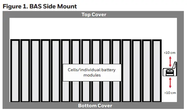
The BAS Series are automotive-grade aerosol sensors that use the principle of light scattering to detect and report thermal runaway events in lithium-ion battery packs. They use the light scattering principle to detect the presence and concentration of aerosols such as smoke, liquid and other particles that are early indicators of a thermal runaway event in an enclosed lithium-ion battery pack. The BAS Series have a factory-programmed, thermal runaway warning threshold of 5000 μg/m³.
General Requirements
The performance of the sensor meets the requirements defined in this specification when the sensor is used under the environmental conditions specified in this document. Any deviation from the use defined in this document will invalidate this specification.
INSTALLATION
Sensor may be installed in any orientation.
2.1a Ensure battery pack vent valve is unblocked.
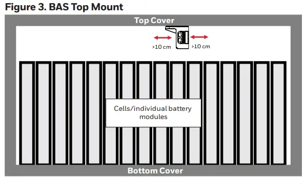
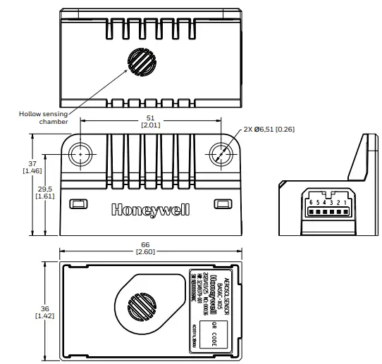
Install sensor with 10 cm clearance on both sides of the hollow sensing chamber.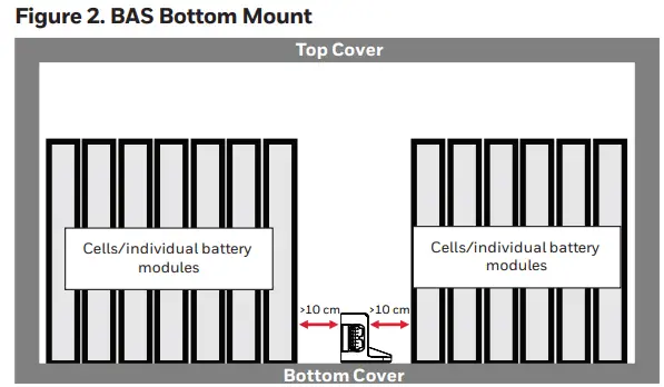
Mount the sensor using two mounting holes and two M6 screws.
10 Nm max. torque for mounting screw.
Mating connector: TE MPN 175507-2
BATTERY SAFETY AEROSOL SENSOR BAS SERIES
Mounting Dimensions
Figure 4. Mounting Dimensions mm [in] (for reference only)
| TABLE 1. MECHANICAL SPECIFICATIONS | |
| Parameter | Characteristic |
| Mounting screw | M6 |
| Adapter connector model | 175507-2 |
| Recommended torque | 10 N m |
| Recomended clearance | 10 cm |
| TABLE 2. PINOUT FOR CAN VERSIONS | |
| Pin Number | Name |
| 1 | Request |
| 2 | CAN_L |
| 3 | CAN_H |
| 4 | Wake-Up |
| 5 | GND |
| 6 | Vcc |
| TABLE 3. GENERAL SPECIFICATIONS1 | |
| Characteristic | Parameter |
| Operating temperature range | -40°C to 85°C [-40°F to 185°F] |
| Particulate matter measurement range | 200 mg/m3 to 10000 mg/m3 |
| Accuracy | ≤±15 % at threshold concentration of 5000 mg/m³ |
| Response time | ≤1 s |
| Current consumption (average): ECO mode Continuous working mode | <0.5 mA <30 mA |
| ECO Mode wake-up threshold | 5000 mg/m3 |
All specifications are at room temperature unless otherwise noted.
| TABLE 4. ELECTRICAL SPECIFICATIONS 1 | ||||
| Characteristic | Min. | Typ. | Max. | Unit |
| Supply voltage (Vs) | 8 | 12 | 16 | Vdc |
| Wake-up signal: High level voltage Low level voltage Output current | 8 — 0.6 | 12 — 1.2 | 16 0.5 1.8 | Vdc Vdc mA |
| REQUEST Input from from BMS to BAS: High level voltage Over voltage capability | 8 — | 12 — | 16 24 | Vdc Vdc |
| Reverse voltage capability | -14 | — | — | Vdc |
1 All specifications are at room temperature unless otherwise noted.
| TABLE 5. COMMUNICATIONS SETTINGS | |||
| Baud Rate | ID | Period | Length |
| 500 kbps | 0x667 | 1 s | 8 Bytes |
| TABLE 6. MESSAGE FORMAT | |||
| Byte | Name | Definition | |
| BYTE0 | particulate matter concentration | — | |
| BYTE1 | particulate matter concentration | — | |
| BYTE2 | Low-power mode wake-up threshold | — | |
| BYTE3 | Low-power mode wake-up threshold | — | |
|
BYTE4 | 0-2 | status | 0x00 = normal 0x01 = alarm 0x02 = reserved |
|
3-7 |
fault | 0x00 = normal 0x01 = photoelectric device fault 0x02 = Vs over voltage 0x03 = Vs under voltage others = reserved | |
| BYTE5 | 0-3 | rolling counter | — |
| BYTE6 | 4-7 | — | — |
| BYTE7 | CRC check code | — | |
THERMAL RUNAWAY WARNING
Figure 5. State Diagram for Operating Modes
Operation Mode
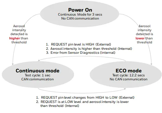
The BAS Series is designed to work in two operating modes:
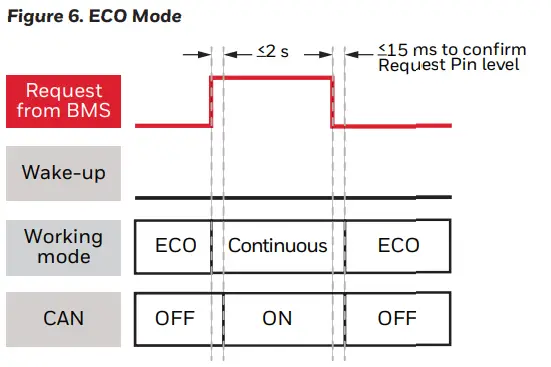
ECO Mode
The sensor operates in ECO Mode when the request pin voltage is set to low. The sensor wakes up for 200 ms and hibernates for the remaining 12000 ms (typical) to reduce power consumption during each measurement cycle of 12200 ms (default value). In ECO Mode, CAN communication is disabled. If the sensor detects an aerosol concentration above the set threshold, a wake-up signal is sent to the BMS (Battery Management System) to initiate a full battery system check.
Continuous Mode
The sensor operates in Continuous Mode when the request pin voltage is set to high by the BMS. CAN communication is enabled in Continuous Mode. In Continuous Mode, the sensor monitors and outputs the aerosol concentration to the BMS using CAN communication. The sensor may be switched to ECO Mode by setting the request pin voltage to low.
Signal Timing Diagram
The timing diagram outlines the timing of events in the right order.
Request Signal Set to High
The BAS enters Continuous mode due to Request signal set to high by the BMS.
Wake-up Signal Signal Set to High
The BAS sets its Wake-up signal to high when it is in ECO mode and the detected aerosol concentration is above the 5000 μg/m3 threshold..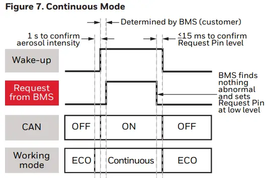
HARDWARE INTERFACE
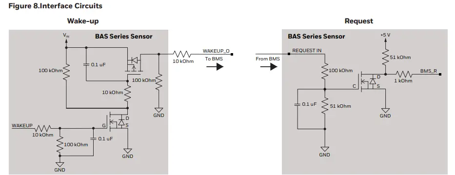
- Recommended Wake-up Pin Interface Circuit at BMS
The Wake-up signal is a logic signal from the BAS sensor to the BMS. See table below. - Recommended Request Pin Interface Circuit at BMS
The Request signal is a logic signal from the BMS to the BAS sensor. See table below. The default state is active low.
Figure 8.Interface Circuits
| TABLE 7. WAKE-UP SIGNAL | ||||
| Parameter | Min. | Typ. | Max. | Unit |
| High level voltage | 8 | 12 | 16 | Vdc |
| Low level voltage | — | — | 0.5 | Vdc |
| Output capability | 6 | 12 | 18 | mA |
| TABLE 8. REQUEST SIGNAL | ||||
| Parameter | Min. | Typ. | Max. | Unit |
| High level voltage | 8 | 12 | 16 | Vdc |
| Low level voltage | — | — | 0.5 | Vdc |
FIRMWARE INTERFACE
Signal Description
| TABLE 9. SIGNAL DESCRIPTION | ||
| Category | Signal Name | Signal Description |
| Thermal Runaway Warning | SmokeSensor_Monitor_Density | Aerosol Concentration measured in mg/m3 unit |
| Thermal Runaway Warning | SmokeSensor_Status | Aerosol concentration Alarm, triggered when the aerosol con- centration exceeds threshold value (5000 mg/m3) |
| BAS Self – Test | SmokeSensor_FaultInfo | Diagnostics feature indicates normal and abnormal function- ality of the sensor, abnormality covers internal failure due to photoelectric fault, Over voltage and under voltage conditions of the sensor |
| BAS Self – Test | SmokeSensor_CRC | Microcontroller EEPROM CRC fault indicator |
BAS Frame and Signal Information
| TABLE 10. PINOUT FOR CAN VERSIONS | ||||||||
|
Signal Name |
General Description | Start Bit | Length (bit) |
Range | Scaling Factor | Offset | Unit |
Usage |
| SmokeSensor_ Monitor_Density | Aerosol concentration | 0 | 16 | 0-10000 | 1 | 0 | mg /m³ | Aerosol Concentration |
| SmokeSensor_ FaultThreshold | Aerosol Concentration Threshold Value | 16 | 16 | 0-10000 | 1 | 0 | – | Aerosol Concentration Thresh- old Value (wakeup threshold) |
| SmokeSensor_Status | Aerosol Sensor Status | 32 | 3 | 0-7 | 1 | 0 | – | 0x00: Normal 0x01: Alarm Rest: Reserved |
|
SmokeSensor_ FaultInfo |
The Details Fault Sta- tus of Aerosol Sensor |
35 |
5 |
0-31 |
1 |
0 |
– | 0x00: Normal 0x01: photoelectric device fault 0x02: power supply over voltage fault 0x03: power supply under voltage fault Rest: Reserved |
| Reserved_Bits0 | Reserved Bits, Not Used Now | 40 | 8 | – | — | — | – | Not used, Reserved for More Information Later. Now Initialed as 0 |
| SmokeSensor_ Counter | Rolling Counter | 48 | 4 | 0-15 | 1 | 0 | – | 0 -15: Means the different CAN Frame |
| Reserved_Bits1 | Reserved Bits, Not Used Now | 52 | 4 | – | – | – | – | Not used, Reserved for More Information Later. Now Initialed as 0 |
| SmokeSensor_CRC | The CRC Value For Byte0 to Byte6 | 56 | 8 | 0-255 | 1 | 0 | – | The CRC Value |
DBC Parse
- Frame ID: 0x3C4
- Frame Period: 1s
- Function: Report real-time particulate matter concentration and fault information in Continuous mode.
Layout Diagram of BAS Frame Message Structure
WARRANTY/REMEDY
Honeywell warrants goods of its manufacture as being free of defective materials and faulty workmanship during the applicable warranty period. Honeywell’s standard product warranty applies unless agreed to otherwise by Honeywell in writing; please refer to your order acknowledgment or consult your local sales office for specific warranty details. If warranted goods are returned to Honeywell during the period of coverage, Honeywell will repair or replace, at its option, without charge those items that Honeywell, in its sole discretion, finds defective. The foregoing is buyer’s sole remedy and is in lieu of all other warranties, expressed or implied, including those of merchantability and fitness for a particular purpose. In no event shall Honeywell be liable for consequential, special, or indirect damages.
While Honeywell may provide application assistance personally, through our literature and the Honeywell web site, it is buyer’s sole responsibility to determine the suitability of the product in the application. Specifications may change without notice. The information we supply is believed to be accurate and reliable as of this writing. However, Honeywell assumes no responsibility for its use.
WARNING
PERSONAL INJURY
DO NOT USE these products as safety or emergency stop devices or in any other application where failure of the product could result in personal injury.
Failure to comply with these instructions could result in death or serious injury.
For more information
Honeywell Sensing and Safety Technologies services its customers through a worldwide network of sales offices and distributors. For application assistance, current specifications, pricing or the nearest Authorized Distributor, visit our website or call:
USA/Canada +1 302 613 4491
Latin America +1 305 805 8188
Europe +44 1344 238258
Japan +81 (0) 3-6730-7152
Singapore +65 6355 2828
Greater China +86 4006396841
Honeywell
Sensing and Safety Technologies
830 East Arapaho Road
Richardson, TX 75081
sps.honeywell.com/ast


