AiM MXL2 Data Storage Expansion Memory Module User Manual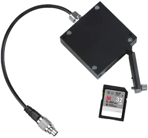
What is Memory Module
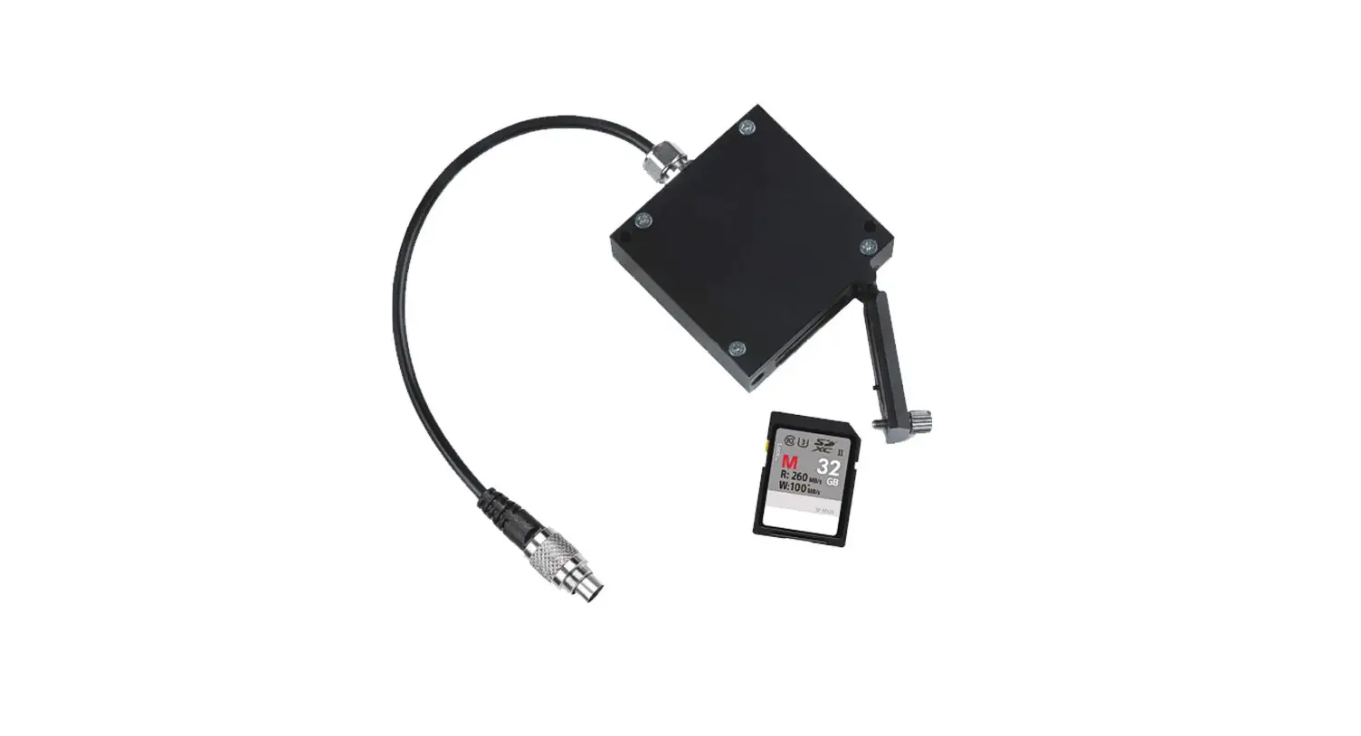
Memory Module is the AiM mass data storage expansion for car/bike installations. It is connected to AiM loggers via a 40cm cable and communicates using AiM proprietary CAN bus.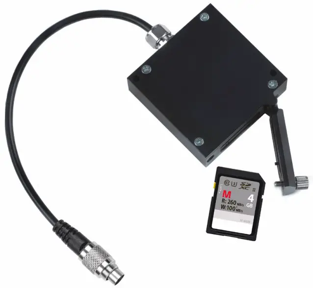
Note: the SD card is not included in the kit.
AiM devices compatibility
The following table shows which AiM dashes/loggers are compatible with Memory Module and from which firmware version.
| Device | Memory Module | Firmware Version |
|---|---|---|
| MXL2 | Yes | From firmware version 1.26.08 onward |
| MXG | Yes | From firmware version 1.26.08 onward |
| MXS | Yes | From firmware version 1.26.08 onward |
| EVO4S | Yes | From firmware version 1.26.08 onward |
| EVO5 | Yes | From firmware version 1.26.08 onward |
| MXS 1.2 | Yes | From firmware version 2.26.48 onward |
| MXP | Yes | From firmware version 2.26.48 onward |
| MXG 1.2 | Yes | From firmware version 2.26.48 onward |
| MXS 1.2 Strada | No | N/A |
| MXP Strada | No | N/A |
| MXG 1.2 Strada | No | N/A |
| MXsl | No | N/A |
| MXm | No | N/A |
| Solo 2 | No | N/A |
| Solo 2 DL | No | N/A |
Connection
Memory Module can be connected to all new generation AiM loggers:
- MX, MX 1.2 series and EVO5: connect it to cable labelled “Exp” of 37 pins Deutsch connector harness
- EVO4S: connect it to 5 pins Binder 712 female connector labelled “Exp”
How does Memory Module work
Memory Module stores data sampled by your AiM logger. No configuration is needed:
- just connect Memory Module to your AiM logger before it starts recording
- Memory Module and AiM logger store data simultaneously
When the session is over:
- get the SD card off the Module and place it in your PC SD slot
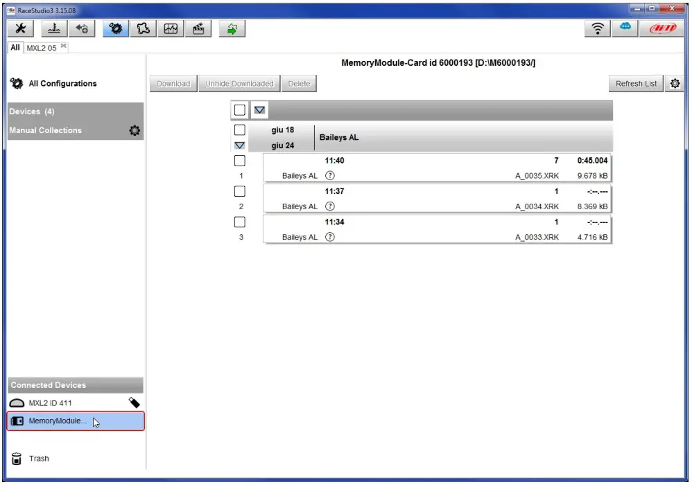
- run Race Studio 3 software
- click on the setting icon

- click on Memory Module (bottom left of the software page)
- “Download” page shows up: perform data download as for any AiM device

- click Analysis button to start analysing your data.
Memory Module LED working mode
Memory Module features a front LED.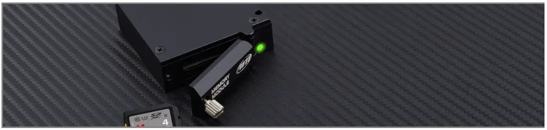
The table below shows its working mode:
| Led status | Meaning |
| Green Steady | Memory Module and Logger are recording |
| Green blinking 1 Hz | Memory Module connected to logger but not recording |
| Green blinking 3Hz | SD Missing |
| Red steady –>Red blinking 1Hz ->Green blinking 1Hz | FirmUp start –>writing –> done |
| Red steady –>Red blinking 1Hz | FirmUp Failed Solution: Disconnect Memory Module from the network, connect it directly to the logger, re-start FirmUp |
Supported SD card dimensions and format
The recommended SD memory sizes for use with AIM dashes is 4GB. Other SD sizes should work, provided that the SD is formatted as FAT32 (exFAT and NTFS do NOT work).
The operation of the memory modules is affected by the SD card speed for specific operations. We found that most class 10 and above SD cards with sizes up to 32GB work reliably.
According to our testing, most SD cards with higher sizes do not work. Furthermore, these SD cards are not shipped with FAT32 formatting by default, so they are not recognized by the memory modules.
Dimensions, pinout and technical characteristics
The drawing here below shows the Memory Module dimensions in mm [inches].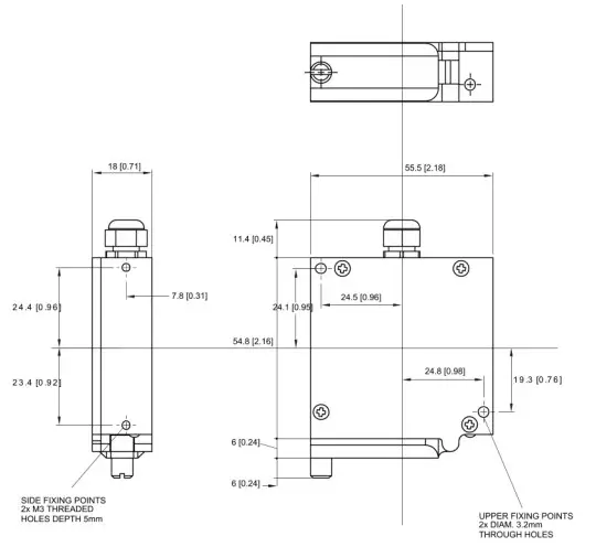
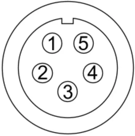
Memory Module cable ends with a 5 pins Binder 712 male connector. Here below it is shown, front view, with its pinout.
| Binder connector pin | Pin function |
|---|---|
| 1 | CAN High |
| 2 | GND |
| 3 | +Vb |
| 4 | CAN Low |
| 5 | n.c. |
Memory Module technical characteristics are:
- Max power consumption: 50 mA
- Cable length: 40cm
- Cable part number: X08MMD040
- Dimensions: 55.5×78.3×18 mm
- Weight: 103g
- Waterproof: IP65


