Hypertherm 088112 Powermax45 XP Hand System
WARNING
- EXPLOSION HAZARD – CUTTING WITH ALUMINUM NEAR WATER Do not cut aluminum alloys underwater or on a water table unless you can prevent the accumulation of hydrogen gas. Never cut aluminum-lithium alloys in the presence of water. Aluminum can react with water to produce hydrogen, resulting in a potentially explosive condition that can detonate during plasma cutting operations. Refer to the Safety and Compliance Manual (80669C) for more information.
- EXPLOSION HAZARD – CUTTING WITH FUEL GASES Do not use combustible fuel gases or oxidizing gases with Powermax systems. These gases can result in explosive conditions during plasma cutting operations.
- TOXIC FUMES CAN CAUSE INJURY OR DEATH Some metals, including stainless steel, may release toxic fumes when cut. Make sure your work site has adequate ventilation to ensure that the air quality level meets all local and national standards and regulations. Refer to the Safety and Compliance Manual (80669C) for more information.
Using the cut charts
The cut charts in this section are intended to provide a good starting point. Adjust the variables in the cut charts as needed to achieve optimal results for your cutting equipment and environment.
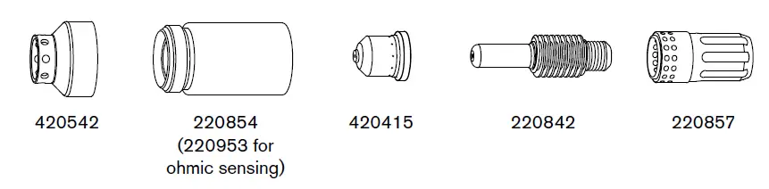
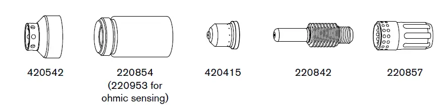
Cut charts are provided for each set of mechanized cutting and marking consumables. A consumable diagram with part numbers precedes each cut chart.
Cut charts are included for:
- Cutting mild steel, stainless steel, and aluminum at 45 A with air using shielded consumables
- Cutting mild steel and stainless steel with air using FineCut consumables
- Cutting stainless steel at 45 A with F5 using shielded consumables
- Marking and dimpling at 10 – 25 A with air and argon using Marking consumables
Each cut chart may contain the following information:
- Amperage setting – The amperage setting at the top of the page applies to all the settings given on that page. In FineCut charts, the amperage setting for each thickness is included in the cut chart.
- Material Thickness – Thickness of the workpiece (metal plate being cut).
- Torch-to-Work Distance – For shielded consumables, the distance between the shield and the workpiece during cutting. For unshielded consumables, the distance between the nozzle and the workpiece during cutting. This is also known as cut height.
- Initial Pierce Height – Distance between the shield (shielded) or the nozzle (unshielded) and the workpiece when the torch is fired, prior to descending to the cut height. In marking charts, this is referred to as Initial Marking Height.
- Pierce Delay Time – Length of time the triggered torch remains stationary at the pierce height before the torch starts the cutting motion. In marking charts, this is referred to as Delay Time.
- Best Quality Settings (cut speed and voltage) – Settings that provide the starting point for finding the best cut quality (best angle, least dross, best cut-surface finish). Adjust the speed for your application and table to obtain the desired result.
- Production Settings (cut speed and voltage) – 70% to 80% of the maximum speed ratings. These speeds result in the greatest number of cut parts, but not necessarily the best possible cut quality.
- The arc voltage increases as the consumables wear, so the voltage setti ng may need to be increased to maintain the correct torch-to-work distance. Some CNCs monitor the arc voltage and adjust the torch lifter automatically.
- Kerf Width – Width of material removed by the cutting process. The kerf widths were obtained with the “Best Quality” settings and are for reference only. Differences between installations and material composition may cause actual results to vary from those shown in the tables. Width and Depth – The marking and dimpling cut charts list the profile dimensions of the mark or dimple.
- Hot flow rate – Plasma is on, the system is operating at running current, and the system is in a steady state at the default system pressure (cutflow, or automatic mode).
- Cold flow rate – Plasma is off and the system is in a steady state with gas flowing through the torch at the default system pressure (postflow). Hypertherm collected the cut chart data under laboratory test conditions using new consumables.
Marking and Dimpling – Air – Shielded
Mild steel
| Current | Torch-to-Work Distance | Initial Marking Height | Delay Time | Marking Speed | Arc Voltage | Width | Depth | |||||
| A | mm | in | mm | in | seconds | mm/min | in/min | volts | mm | in | mm | in |
| Light marking | ||||||||||||
| 10 | 6.4 | 0.25 | 6.4 | 0.25 | 0 | 2540 | 100 | 134 | 2.79 | 0.11 | <0.02 | <0.001 |
| Heavy marking | ||||||||||||
| 10 | 4.6 | 0.18 | 4.6 | 0.18 | 0 | 2540 | 100 | 111 | 2.79 | 0.11 | 0.09 | 0.0035 |
| Dimpling | ||||||||||||
| 10 | 6.4 | 0.25 | — | — | 0.05 | — | — | — | 1.98 | 0.078 | 0.25 | 0.01 |
Stainless steel
| Current | Torch-to-Work Distance | Initial Marking Height | Delay Time | Marking Speed | Arc Voltage | Width | Depth | |||||
| A | mm | in | mm | in | seconds | mm/min | in/min | volts | mm | in | mm | in |
| Light marking | ||||||||||||
| 10 | 5.1 | 0.2 | 5.1 | 0.2 | 0 | 5080 | 200 | 98 | 2.03 | 0.08 | <0.02 | <0.001 |
| Heavy marking | ||||||||||||
| 10 | 6.4 | 0.25 | 6.4 | 0.25 | 0 | 3175 | 125 | 133 | 2.54 | 0.1 | 0.08 | 0.003 |
| Dimpling | ||||||||||||
| 10 | 6.4 | 0.25 | — | — | 0.05 | — | — | — | 2.03 | 0.08 | 0.23 | 0.009 |
Aluminum
| Current | Torch-to-Work Distance | Initial Marking Height | Delay Time | Marking Speed | Arc Voltage | Width | Depth | |||||
| A | mm | in | mm | in | seconds | mm/min | in/min | volts | mm | in | mm | in |
| Marking | ||||||||||||
| 11 | 2.5 | 0.1 | 5.1 | 0.2 | 0 | 5080 | 200 | 98 | 0.89 | 0.035 | <0.02 | <0.001 |
| Dimpling | ||||||||||||
| 10 | 3.2 | 0.125 | — | — | 0.1 | — | — | — | 0.89 | 0.035 | 0.09 | 0.0035 |
Gas flow rate – slpm / scfh
- 137/290 Hot (cutflow)
- 141/300 Cold (postflow)
Marking and Dimpling – Argon – Shielded
Mild steel
| Current | Torch-to-Work Distance | Initial Marking Height | Delay Time | Marking Speed | Arc Voltage | Width | Depth | |||||
| A | mm | in | mm | in | seconds | mm/min | in/min | volts | mm | in | mm | in |
| Light marking | ||||||||||||
| 10 | 2.0 | 0.08 | 2.0 | 0.08 | 0 | 3175 | 125 | 44 | 1.22 | 0.048 | <0.02 | <0.001 |
| Heavy marking | ||||||||||||
| 15 | 1.5 | 0.06 | 1.5 | 0.06 | 0 | 3175 | 125 | 44 | 1.22 | 0.048 | <0.02 | <0.001 |
| Dimpling | ||||||||||||
| 20 | 3.2 | 0.125 | — | — | 0.2 | — | — | — | 0.99 | 0.039 | <0.02 | <0.001 |
Stainless steel
| Current | Torch-to-Work Distance | Initial Marking Height | Delay Time | Marking Speed | Arc Voltage | Width | Depth | |||||
| A | mm | in | mm | in | seconds | mm/min | in/min | volts | mm | in | mm | in |
| Light marking | ||||||||||||
| 12 | 2.5 | 0.1 | 2.5 | 0.1 | 0 | 3175 | 125 | 46 | 1.40 | 0.055 | <0.02 | <0.001 |
| Heavy marking | ||||||||||||
| 15 | 2.5 | 0.1 | 2.5 | 0.1 | 0 | 2540 | 100 | 46 | 2.16 | 0.085 | 0.02 | 0.001 |
| Dimpling | ||||||||||||
| 10 | 3.2 | 0.125 | — | — | 0.2 | — | — | — | 0.94 | 0.037 | 0.18 | 0.007 |
Aluminum
| Current | Torch-to-Work Distance | Initial Marking Height | Delay Time | Marking Speed | Arc Voltage | Width | Depth | |||||
| A | mm | in | mm | in | seconds | mm/min | in/min | volts | mm | in | mm | in |
| Marking | ||||||||||||
| 16 | 0.5 | 0.02 | 0.5 | 0.02 | 0 | 4445 | 175 | 42 | 0.63 | 0.025 | <0.02 | <0.001 |
| Dimpling | ||||||||||||
| 20 | 0.5 | 0.02 | — | — | 0.4 | — | — | — | 0.66 | 0.026 | 0.04 | 0.0015 |
Gas flow rate – slpm / scfh
- 120/255 Hot (cutflow)
- 123/260 Cold (postflow)


