![]() MOUNTING BASES AND ACCESSORIES
MOUNTING BASES AND ACCESSORIES
SELECT SERIES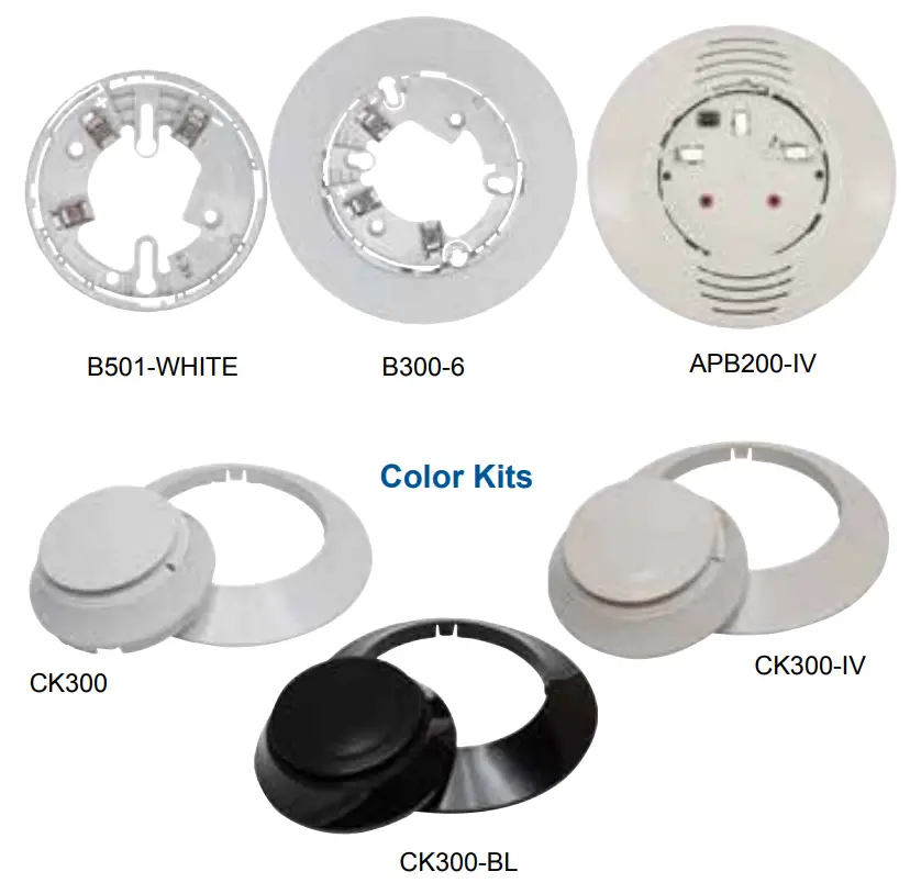
Description
To meet local code and application requirements, Mircom offers standard 4” and 6” bases, as well as, specialty base designs including relay, isolator, sounder and low frequency sounder options for Select Series detectors.
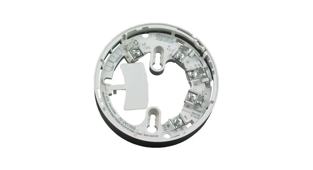
The standard 4” and 6” bases offer a plug-in detector base intended for use in intelligent systems. The 4” base offers a compact design while the 6” base provides compatibility with a wider range of junction boxes.
See the Select Series Junction Box Selection Guide on the next page for junction box options.
The Select Series specialty bases support application driven requirements.
Relay bases (B224RB(A)-WH/B224RB(A)-IV) provide one form C contact relay for control of auxiliary functions, such as door closure and elevator recall. The relay can operate in two different modes (short and long delay). The activation time for the short delay is 60 ms to 100 ms, while the activation time for the long delay is 6 sec to 10 sec.
Isolator bases (B224BI(A)-WH/B224BI(A)-IV) allow the Signaling Line Circuit (SLC) loop to operate under fault conditions created from a short circuit preventing an entire
communication loop from being disabled. The base isolates the section of the loop containing the short circuit from the remainder of the circuit and automatically restores when the fault is corrected.
Features
- Bases enable quick and secure detector plug-in
- SEMS screws provide easy wiring connection
- Support for 12-24 AWG provides installation flexibility
- Multiple base formats meet application requirements
- Standard white color with ivory options
- UL 268 compliant
- Canadian models compliant with CAN/ULC S529
- Mechanical locking feature restricts removal of attached sensor head
Speciality Base Features
- Pre-wired mounting plate simplifies installation
- Application driven feature sets
- Sounder bases both UL 268 and UL 464 compliant
- Canadian sounder base models compliant with both CAN/ULC S529 and CAN/ULC S525
- Additional terminal connections on Canadian models enable silence feature
The Select Series sounder and low frequency sounder bases are designed for new and existing dwelling unit applications. They offer maximum flexibility in installation, configuration, and operation to meet or exceed UL 268 and UL 464/ CAN-ULC S529 and CAN-ULC S525 requirements.
The Select Series low frequency sounder bases are designed to meet the NFPA 72 sleeping space requirement to produce a fundamental frequency of 520 Hz +/- 10% with a square wave or its equivalent.
The B200SR(A) sounder and LF sounder bases (B200SRWH/B200SR-IV/B200SR-LF-WH/B200SR-LF-IV) are fully compatible with existing sounder base installations.
The Sounder bases adopt the same address as the detector, but use a unique device type on the loop. The Fire Alarm Control Panel (FACP) can use that address to command an individual or a group of sounders to activate. The command set from the FACP can be tailored to multiple event-driven tone outputs allowing selection of volume, tone, and group.
The sounder bases recognize the System Sensor synchronization protocol. This enables it to be used as a component of the general evacuation signal – along with other System Sensor AV appliances – when connected to a power supply or FACP output capable of generating the System Sensor synchronization pulses.
![]() CATALOG NUMBER 5900
CATALOG NUMBER 5900
Note: Refer to ordering information for agency listing details.
NOT TO BE USED FOR INSTALLATION PURPOSES.
THIS INFORMATION IS FOR MARKETING PURPOSES ONLY AND NOT INTENDED TO DESCRIBE THE PRODUCTS TECHNICALLY.
firealarmresources.com
Physical Specifications
| Model Color: White | Model Color: Ivory | Diameter |
| B501-WHITE | B501-IV | 4.0″ (10.2 cm) |
| B300-6 B300A-6 | B300-6-IV B300A-6-IV | 6.1″ (155 mm) |
| B200SR-WH B200SRA-WH B200SR-LF-WH APB200-WH APB200-LF-WH APB200A-WH APB200COA-WH | B200SR-IV B200SRA-IV B200SR-LF-IV APB-200-IV APB200-LF-IV APB200A-IV APB200COA-IV | 6.85″ (17.4 cm) |
| B224BI-WH B224RB-WH B224BIA-WH B224RBA-WH | B224BI-IV B224RB-IV B224BIA-IV B224RBA-IV | 6.85″ (17.4 cm) |
| Base Height (without sensor) | ||
| B501-WHITE | B501-IV | 0.74″ (18.8 mm) |
| B300-6 B300A-6 | B300-6-IV B300A-6-IV | 0.76″ (19 mm) |
| B200SR-WH B200SRA-WH B200SR-LF-WH APB200-WH APB200-LF-WH APB200A-WH APB200COA-WH | B200SR-IV B200SRA-IV B200SR-LF-IV APB-200-IV APB200-LF-IV APB200A-IV APB200COA-IV | 1.6″ (4.1 cm) |
| B224BI-WH B224RB-WH B224BIA-WH B224RBA-WH | B224BI-IV B224RB-IV B224BIA-IV B224RBA-IV | 1.6″ (4.1 cm) |
| Weight | ||
| B501-WHITE | B501-IV | 0.32 lb (145 gm) |
| B300-6 B300A-6 APB200-WH APB200A-WH | B300-6-IV B300A-6-IV APB-200-IV APB200A-IV | 0.32 lb (145 gm) |
| B200SR-WH B200SRA-WH | B200SR-IV B200SRA-IV | 0.50 lb (227 gm) |
| B200SR-LF-WH APB200-LF-WH APB200COA-WH | B200SR-LF-IV APB200-LF-IV APB200COA-IV | 0.6 lb (272 gm) |
| B224BI-WH B224RB-WH B224BIA-WH B224RBA-WH | B224BI-IV B224RB-IV B224BIA-IV B224RBA-IV | 0.50 lb (227 gm) |
| Wire Gauge | ||
| B501-WHITE | B501-IV | 18 AWG (0.823 mm²) to 12 AWG (3.31 mm²) |
| B300-6 B300A-6 | B300-6-IV B300A-6-IV | 18 AWG (0.823 mm²) to 12 AWG (3.31 mm²) |
| B200SR-WH B200SRA-WH B200SR-LF-WH APB200-WH APB200-LF-WH APB200A-WH APB200COA-WH | B200SR-IV B200SRA-IV B200SR-LF-IV APB-200-IV APB200-LF-IV APB200A-V APB200COA-IV | 14 AWG (2.08 mm²) to 12 AWG (3.31 mm²) |
| B224BI-WH B224RB-WH B224BIA-WH B224RBA-WH | B224BI-IV B224RB-IV B224BIA-IV B224RBA-IV | 18 AWG (0.823 mm²) to 12 AWG (3.31 mm²) |
| Temperature Range | ||
| Refer to applicable sensor Operating Temperature Range | ||
| Temperature Range | ||
| 10% to 93% RH non-condensing | ||
Electrical Spefications
B501-WHITE, B501-IV | ||||
| Operating Voltage | 15 to 32 VDC | |||
| Standby Current | 150 μA | |||
B300-6, B300-6-IV, B300A-6, B300A-6-IV | ||||
| Operating Voltage | 15 to 32 VDC | |||
| Standby Current | 170 μA max. | |||
B224BI-WH, B224BI-IV, B224BIA-WH, B224BIA-IV | ||||
| Operating Voltage | 15 to 32 VDC | |||
| Standby Current | 450 μA max | |||
| Isolation Current | 15 mA max | |||
B224RB-WH, B22RB-IV, B224RBA-WH, B224RBA-IV | ||||
| Operating Voltage | 15 to 32 VDC | |||
| Standby Current | 170 μA max. | |||
| Set Time | Position 1, Short Delay: 60 to 100 ms Position 2, Long Delay: 6 to 10 sec | |||
| Reset Time | 20 ms max. | |||
| Relay Characteristics | 2 coil latching relay 1 Form C contact | |||
UL/ULC Rating: | ||||
| Current Rating | Maximum Voltage | Maximum Voltage | Application | |
| 2 A | 25 VAC | PF = 0.35 | Non-coded | |
| 3A | 30 VDC | Resistive | Non-coded | |
| 2A | 30 VDC | Resistive | Coded | |
| 0.46 A | 30 VDC | (L/R = 20ms) | Non-coded | |
| 0.7 A | 70.7 VAC | PF = 0.35 | Non-coded | |
| 0.9A | 125 VDC | Resistive | Non-coded | |
| 0.5 A | 125 VDC | PF = 0.75 | Non-coded | |
| 0.3 A | 125 VDC | PF = 0.75 | Non-coded | |
B200SR-WH,B200SR-IV,B200SRA-WH, B200SRA-IV | ||||
| External Supply Electrical Ratings: | ||||
| External Supply Voltage | 16 to 33 VDC (VFWR) | |||
| Standby Current | 500 μA maximum | |||
| Alarm Current: | 35 mA maximum | |||
SLC Electrical Ratings: | ||||
| SLC Operating Voltage: | 15 to 32 VDC | |||
| SLC Standby Current: | 300 μA maximum | |||
| Sound Output | Greater than 85 dBA minimum measured in a UL reverberant room/ ULC anechoic room at 10 feet, 24 Volts (in continuous tone) | |||
B200SR-LF-WH, B200SR-LF-IV | ||||
External Supply Electrical Ratings: | ||||
| External Supply Voltage | 16 to 33 VDC (VFWR) | |||
| Standby Current | 1 mA maximum VDC | |||
| Alarm Current: | 65 mA maximum @ 33.0 VDC 90 mA maximum @ 24.0 VDC 125 mA maximum @16.0 VDC | |||
SLC Electrical Ratings: | ||||
| SLC Operating Voltage: | 15 to 32 VDC | |||
| SLC Standby Current: | Refer to applicable sensor specification. | |||
| Sound Output | Greater than 85 dBA minimum measured in a UL reverberant room at 10 feet, 24 Volts (in continuous tone) | |||
APB200-WH, APB200-IV, APB200A-WH, APB200A-IV | |
External Supply Electrical Ratings: | |
| External Supply Voltage | 16 to 33 VDC (VFWR) |
| Standby Current | 500 μA maximum |
| Alarm Current: | 35 mA maximum (at high volume setting); 15mA maximum (at low volume setting) |
SLC Electrical Ratings: | |
| SLC Operating Voltage: | 15 to 32 VDC |
| SLC Standby Current: | 300 μA maximum |
| High Volume | Greater than 85 dBA minimum measured in a UL reverberant room/ ULC anechoic room at 10 feet (3m), 24 Volts (in continuous tone) |
| Low Volume | Greater than 75 dBA minimum measured in a UL reverberant room/ ULC anechoic room at 10 feet (3m), 24 Volts (in continuous tone |
APB200-LF-WH, APB200-LF-IV | |
External Supply Electrical Ratings: | |
| External Supply Voltage | 16 to 33 VDC (VFWR) |
| Standby Current | 1 mA maximum VDC |
| Alarm Current, High-volume setting: | 70 mA maximum @ 33.0 VDC 90 mA maximum @ 24.0 VDC 140 mA maximum @16.0 VDC |
| Alarm Current, Low-volume setting: | 15 mA maximum @ 33.0 VDC 20 mA maximum @ 24.0 VDC 25 mA maximum @16.0 VDC |
SLC Electrical Ratings: | |
| SLC Operating Voltage: | 15 to 32 VDC |
| SLC Standby Current: | 300 μA maximum (base only, refer to applicable sensor specification) |
Sound Output: | |
| High Volume | Greater than 85 dBA minimum measured in a UL reverberant room/ ULC anechoic room at 10 feet (3m), 24 Volts (in continuous tone) |
| Low Volume | Greater than 75 dBA minimum measured in a UL reverberant room/ ULC anechoic room at 10 feet (3m), 24 Volts (in continuous tone) |
JUNCTION BOX SELECTION GUIDE
| Model | Single Gang | Double Gang | 3.5″Octagonal | 4″ Octagonal | 4″ Square | 4″ Square with mud ring* | 50 mm | 60 mm | 70 mm | 75 mm |
| B501-WHITE B501-IV | No | No | Yes | No | No | Yes | Yes | Yes | Yes | No |
| B300-6 B300-6-IV B300A-6 B300A-6-IV | Yes | No | Yes | Yes | Yes | Yes | No | No | No | No |
| B200SR-WH B200SR-IV B200SRA-WH B200SRA-IV B200SR-LF-WH B200SR-LF-IV APB200-WH APB-200-IV APB200-LF-WH APB200-LF-IV APB200A-WH APB200A-IV APB200COA-WH APB200COA-IV | Yes | Yes | Yes | Yes | Yes | Yes | No | No | No | No |
| B224BI-WH B224BI-IV B224BIA-WH B224BIA-IV | Yes | Yes | Yes | Yes | Yes | Yes | No | No | No | No |
| B224RB-WH B22RB-IV B224RBA-WH B224RBA-IV | Yes | Yes | Yes | Yes | Yes | Yes | No | No | No | No |
*with 3.0” mud ring. Note: Box depth contingent on base and wire size. Refer to National Electric Code or applicable local codes for appropriate recommendations.
Ordering Information
| Model | Description | Color |
| B501-WHITE | 4″ Flangeless mounting base – UL/ ULC | White |
| B501-IV | 4″ Flangeless mounting base – UL/ ULC | Ivory |
| B300-6 | 6″ Flanged mounting base – UL | White |
| B300-6-IV | 6″ Flanged mounting base – UL | Ivory |
| B300A-6 | 6″ Flanged mounting base – ULC | White |
| B300A-6-IV | 6″ Flanged mounting base – ULC | Ivory |
| B200SR-WH | Standard Sounder Base – UL | White |
| B200SR-IV | Standard Sounder Base – UL | Ivory |
| B200SRA-WH | Standard Sounder Base – ULC | White |
| B200SRA-IV | Standard Sounder Base – ULC | Ivory |
| B200SR-LF-WH | Low-frequency Sounder Base – UL | White |
| B200SR-LF-IV | Low-frequency Sounder Base – UL | Ivory |
| APB200-WH | Intelligent Sounder Base – UL | White |
| APB200-IV | Intelligent Sounder Base – UL | Ivory |
| APB200-LF-WH | Intelligent Low-frequency Sounder Base – UL | White |
| APB200-LF-IV | Intelligent Low-frequency Sounder Base – UL | Ivory |
| APB200A-WH | Intelligent Sounder Base – ULC | White |
| APB200A-IV | Intelligent Sounder Base – ULC | Ivory |
| APB200COA-WH | Intelligent Sounder Base (Designed for use with detector heads that provide CO Detection) – ULC | White |
| APB200COA-IV | Intelligent Sounder Base (Designed for use with detector heads that provide CO Detection) – ULC | Ivory |
| B224BI-WH | Isolator Base – UL | White |
| B224BI-IV | Isolator Base – UL | Ivory |
| B224BIA-WH | Isolator Base – ULC | White |
| B224BIA-IV | Isolator Base – ULC | Ivory |
| B224RB-WH | Relay Base – UL | White |
| B224RB-IV | Relay Base – UL | Ivory |
| B224RBA-WH | Relay Base – ULC | White |
| B224RBA-IV | Relay Base – ULC | Ivory |
| Accessories | ||
| CK300 | Color Kit (includes cover and trim ring) – Pack of 10 | White |
| CK300-IV | Color Kit (includes cover and trim ring) – Pack of 10 | Ivory |
| CK300-BL | Color Kit (includes cover and trim ring) – Pack of 10 | Black |
| CK300-IR | PTIR Color Kit (includes cover and trim ring) – Pack of 10 | White |
| CK300-IR-IV | PTIR Color Kit (includes cover and trim ring) – Pack of 10 | Ivory |
| CK300-IR-BL | PTIR Color Kit (includes cover and trim ring) – Pack of 10 | Black |
| TR300 | Trim Ring | White |
| TR300-IR | Trim Ring | Ivory |
| RA100Z | Remote LED Annunciation – UL | Ivory |
| RA100ZA | Remote LED Annunciiator – ULC | Ivory |
Canada
25 Interchange Way
Vaughan, Ontario L4K 5W3
Telephone: (905) 660-4655
Fax: (905) 660-4113
www.mircom.com
U.S.A.
4575 Witmer Industrial Estates
Niagara Falls, NY 14305
Toll Free: (888) 660-4655
Fax Toll Free: (888) 660-4113
![]()
THIS INFORMATION IS FOR MARKETING PURPOSES ONLY AND NOT INTENDED TO DESCRIBE THE PRODUCTS TECHNICALLY.
For complete and accurate technical information relating to performance, installation, testing and certification, refer to technical literature. This document contains intellectual property of Mircom. The information is subject to change by Mircom without notice. Mircom does not represent or warrant correctness or completeness. CAT. 5900 Rev. 0


