
LavoDose Series Proportioning Equipment  Safety
 Safety
READ CAREFULLY BEFORE INSTALLING:
- Read this manual carefully for installation instructions.
- DO NOT INSTALL the dispenser where it is directly exposed to vapors, chemical fumes, or next to heat sources.
- PROTECT YOURSELF – Always wear personal protective equipment. Use gloves, eye ware, and appropriate attire when working with chemicals.
- FOLLOW THE SAFETY AND HANDLING INSTRUCTION of the chemical manufacturer.
- NEVER point the discharge hose at yourself.
- Always check local plumbing codes to ensure compliance.
- THE DISPENSER SHOULD BE INSTALLED approximately 5’ above the chemical container.
Technical Specifications
| Water Inlet | Left or Right |
| Type of Connection | ¾” Female GHT |
| Actuators | Button, Dial, Slide |
| Product Dimensions | 9″ H x 4″ W x 5″ D |
| Operating Pressure | 20PSI to 100PSI |
| Temperature | Max 160 degrees F |
Dilutions may vary. Testing completed at 40PSI with water-thin products. Use this chart as a starting point for your specific chemical.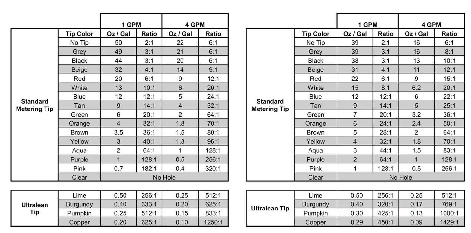
Mounting Instructions
Step 1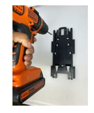
| Use the backplate as a template to mark the mounting hole pattern. Drill a hole for the supplied ¼” anchors and mount the bracket with the screws provided in the accessory kit. |
Step 2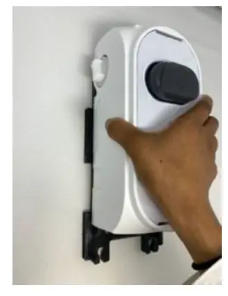
| Attach the system to the backplate and slide it down. The tab will make a clicking noise when the dispenser secured. |
Step 3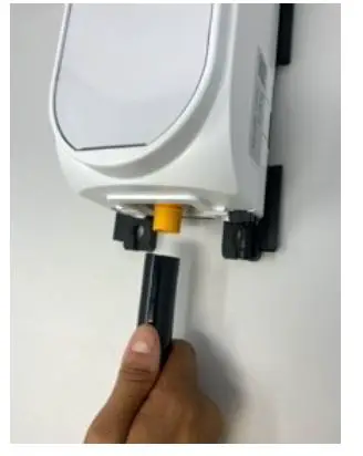
| Slide in the discharge hose (6.5ft or “S” tube) over the barbed fitting and make sure it is secured. |
Step 4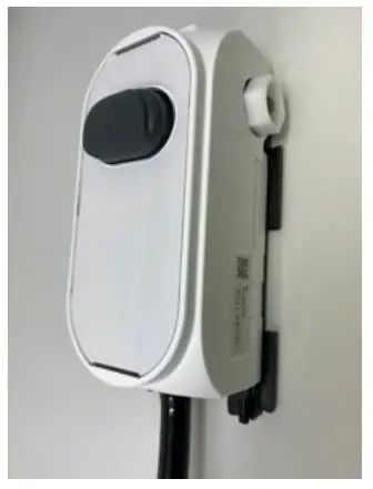
| Connect the water inlet supply. |
Step 5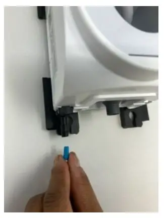
| Select the metering tip for your desired dilution and connect the supply tubing. |
Step 6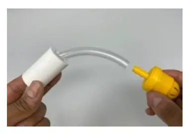
| Connect the ceramic weight on the opposite end of the tube with the foot valve. |
Mounting Instructions
Multiple Unit Installation
After mounting the backplate, follow these instructions:
Step 1 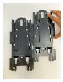
| Slide the second bracket into the slot from top to bottom on the left side of bracket 1 until they are properly aligned and secure. |
Step 2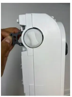
| Unlock the left side of the first system by pulling the rear clip to its outward most position as shown and remove the end cap. |
Step 3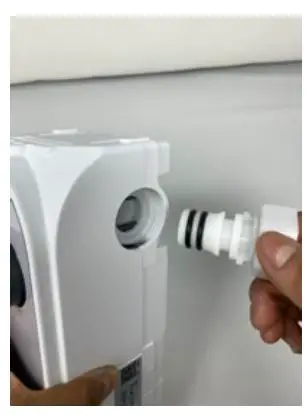
| Unlock the right side of the second system by pulling the clip to its outward most position and remove the water connection. |
Step 4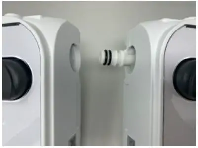
| Insert the coupling nipple into the first unit as illustrated. Connect the second unit to the first. |
Step 5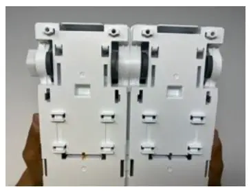
| Apply the combined on to the bracket and complete the installation (follow Step 3 from mounting instructions). |
Troubleshooting
| Problem | Cause | Solution |
|
The system does not dispense solution | 1. Water inlet strainer is clogged 2. Too much water pressure
3. Insufficient water pressure
4. The venturi is clogged
5. Activation valve is clogged by mineral | 1. Clean it or replace if necessary 2. Use a water pressure regulator in case of more than 100PSI
3. 20PSI is the minimum required pressure.
4. Soak venturi in hot water and inspect visually, gently removing debris. Replace the assembly if needed. 5. Soak the valve assembly in a solution of hot water and limescale remover. Replace the assembly if needed. |
| Water flow won’t stop | 1. Activation valve is clogged by minerals or other water-borne debris | 1. Soak the valve parts and valve seat in lime-scale remover to clean. Replace them if necessary. |
| Activation valve is leaking | 1. Valve cap not tight enough to seat
2. Not properly positioned | 1. Firmly hand tighten the valve cap until the leak stops.
2. Reposition the valve or change it if necessary |
| Connections and end cap are leaking | 1. Missing o-ring in the connection fitting and / or end cap 2. O-ring in the connections or end cap are damaged | 1. Apply the o-ring or replace the entire part
2. Replace the o-rings or replace the entire end cap |
| Flex gap is leaking | 1. Flexible membrane is damaged | 1. Replace the Flex Gap |
|
A-gap is spraying out and or leaking | 1. Limescale film or dirt on the A-gap’s upper nozzle
2. Venturi coated with limescale or dirt
3. There is a buildup or clog in the discharge hose
4. Discharge hose is above the dispenser | 1. Soak in hot water and limescale remover to remove buildup. Replace if necessary
2. Soak in hot water and limescale remover to clean. Replace it if necessary
3. Clean the hose to eliminate restriction
4. Make sure the discharge hose dispenses be- low the dispenser insuring no back pressure |
| 1. Insufficient water pressure | 1. 14PSI is the minimum working pressure. | |
| 2. Metering tip clogged | 2. Replace tip | |
| 3. Foot valve clogged | 3. Soak in hot water, hand clean or change it | |
| 4. Venturi clogged | 4. Soak in hot water or limescale remover to clean. Replace it if necessary | |
| Improper concentration of chemical or no suction | 5. Air leak in chemical pick up tubing line | 5. Check the entire line. Replace the tubing check the connections and cable tie |
| 6. Product is too thick | 6. Change the pick up hose. Switch to a bigger diameter. (need ¼ x 5/16 coupler) | |
| 7. Product container is too far from the sys- tem | 7. The standard installation is positioning the tank under the system, 5ft max | |
| 8. Excess concentration | 8. Tip is not the correct one or not inserted fully. | |
| System continues to draw chemical after the valve is closed | 1. Chemical tank is positioned higher than the dispenser causing siphoning | 1. Move chemical container below the dispenser discharge point |
Spare Parts
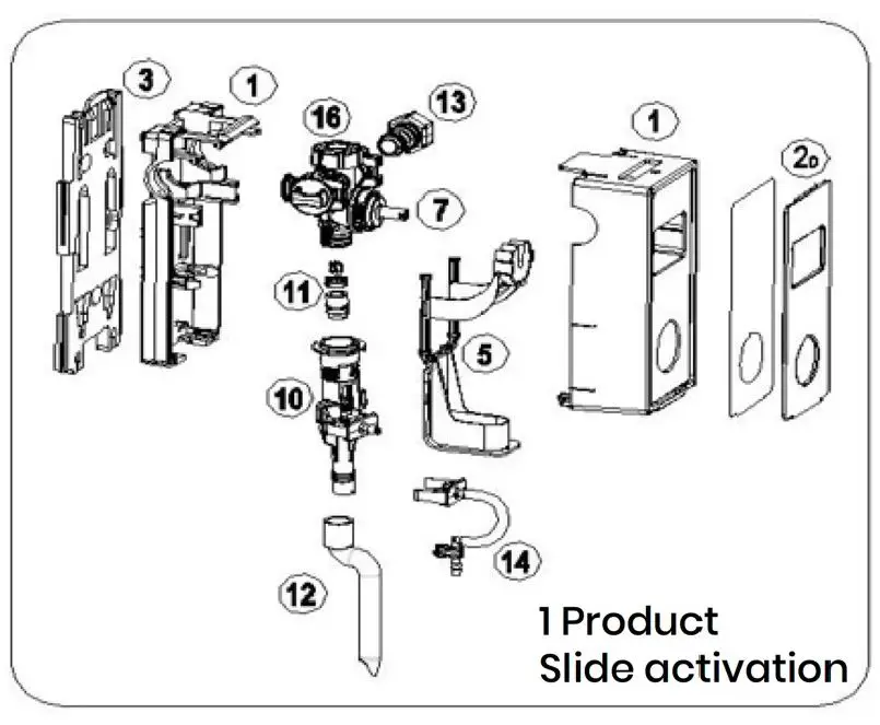
| Other parts not shown above | |||
| # | Description | Lavo Part Number | |
| 1 | Housing (rear + front) | 100-0084 | |
| Clear faceplate – 1 Product Button | 100-0040 | ||
| 2 | Clear faceplate – 1 Product Slide Clear faceplate – 4 Product Button | 100-0041 100-0042 | |
| Clear faceplate – 4 Product Slide | 100-0043 | ||
| 3 | Mounting Bracket | 100-0083 | |
| 4 | Complete Button Spare Kit | 100-0046 | |
| 5 | Complete Slide Spare Kit | 100-0056 | |
| 6 | Complete Selector Spare Kit | 100-0079 | |
| 7 | Complete Activation Valve Spare Kit | 100-0081 | |
| 8 | Flex Gap venturi grey spare kit 1GPM (4lt / min) | 100-0011 | |
| Flex Gap venturi yellow spare kit 4GPM (16lt / min) | 100-0010 | ||
| 9 | Flex Gap backflow Spare Kit | 100-0085 | |
| 10 | Complete Air Gap & Venturi 1GPM (4lt / min) spare kit | 100-0013 | |
| Complete Air Gap & Venturi 4GPM (16lt / min) spare kit | 100-0012 | ||
| 11 | Air Gap Nozzles 1GPM (4lt / min) kit (10 pcs) | 100-0077 | |
| Air Gap Nozzles 4GPM (16lt / min) kit (10 pcs) | 100-0078 | ||
| 12 | Bottle “S” filling hose | 100-0018 | |
| 13 | Water inlet fitting kit | 100-0082 | |
| 14 | Inlet Filling kit – 1 product | 100-0080 | |
| 15 | Bucket filling hose | 100-0019 | |
| Top Filter kit | 100-0047 | ||
| 16 | Flow Stabilizer – 1GPM (4lt / min) | 100-0001 | |
| Flow Stabilizer – 4GPM (16lt / min) | 100-0002 | ||
Other parts not shown above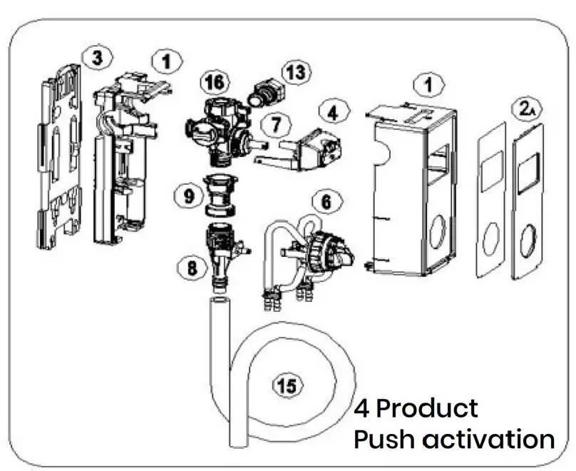
| Description | Lavo Part Number |
| Foot valve + Viton check valve Yellow | 100-0023 |
| PVC clear tubing – 13ft length | 100-0025 |
| LavoDose Drip Tray – 2pcs per box | 100-0032 |
| Standard Metering Tips – 15pcs | 100-0020 |
| Ultra Lean metering Tips – 4pcs | 100-0021 |
| Wire Rack – Four Gallon | 100-0034 |
| 6ft inlet water hose – black | 100-0035 |


