![]()
Communication Lightning Protection
1 Precaution
CAUTION The COM connection for communications is not the shield wire. The COM, RX, and TX wires must connect to each other at all controllers.
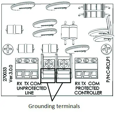
CAUTION Connect the safety ground wire to one of the grounding terminals!
- Install the lightning protector in series on the cable leading from the controllers to the multiplexer. Locate the protector close to the controller. Install a good ground; otherwise, protection is not effective.
- Connect the side marked “Protected” to the controller side. Connect the side markers “Unprotected” to the other side of the cable, leading to the multiplexer.
- Use 3 wire shielded cables (3 + shield) for the communication line. Connect the shielded wire to the safety ground terminal.
CAUTION Do not ground the shield of the protected side.
2 Wiring
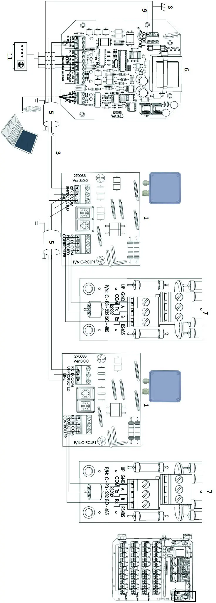 Figure 1: RCLP RS-232 Wiring
CAUTION Ground the RCLP on one side only!
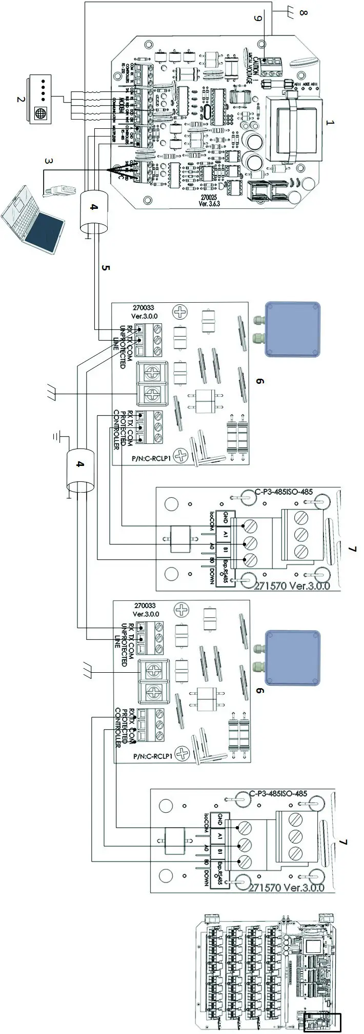
Figure 2: RCLP RS-485 Wiring
| 1: MUX board | 6: RCLP card |
| 2: Modem (priority channels) | 7: Controller RS-232 or RS-485 communication card |
| 3: PC | 8: Neutral |
| 4: Connect shield to ground | 9: Grounding |
| 5: Long distance wiring |
CAUTION Ground the RCLP on one side only!
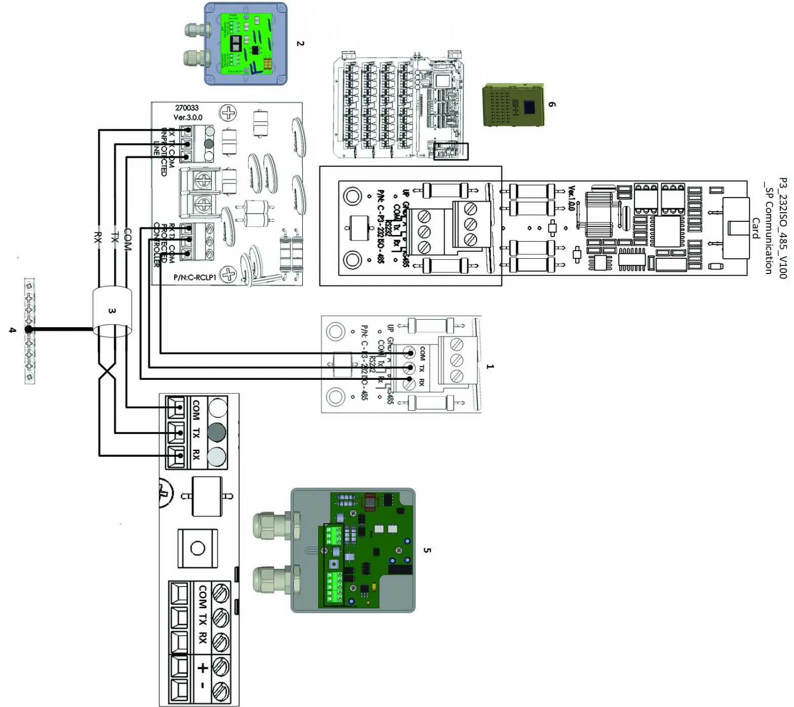
Figure 3: Comm-Box Junction Box RS-232 Wiring
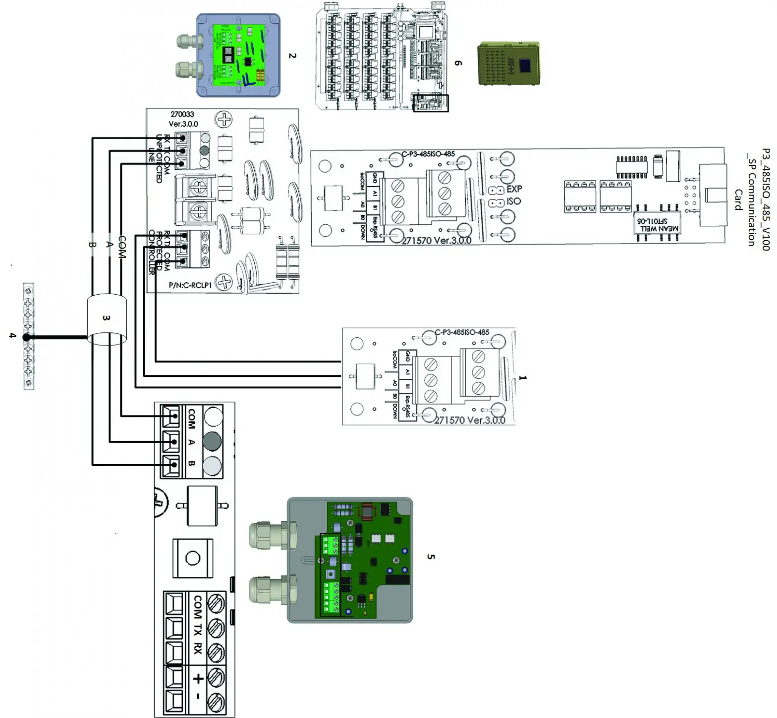
Figure 4: Comm-Box Junction Box RS-485 Wiring
NOTE: Refer to the Comm-Box Manual for details on wiring the Junction Box to the Comm-Box.
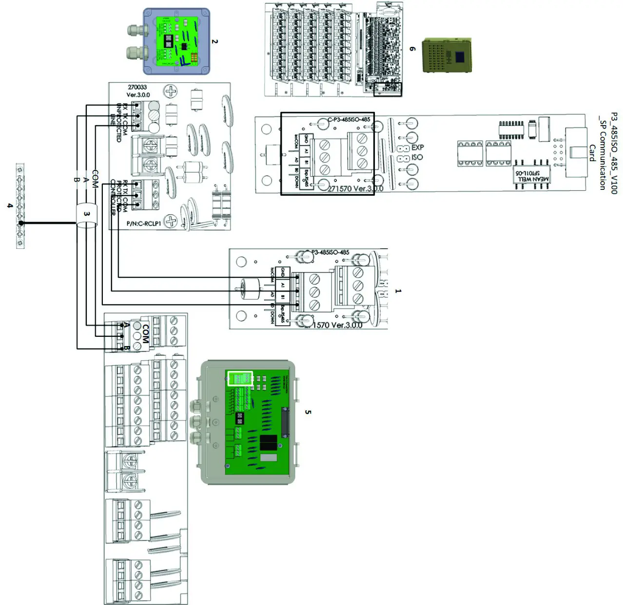 Figure 5: Communicator 2.0 Junction Box RS-232 Wiring
NOTE Refer to the Communicator 2.0 Manual for details on wiring the Junction Box to the Communicator 2.0.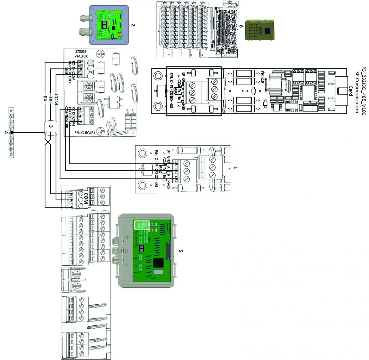
Figure 6: Communicator 2.0 Junction Box RS-485 Wiring
NOTE Refer to the Communicator 2.0 Manual for details on wiring the Junction Box to the Communicator 2.0.
Table 1: Figure 3, Figure 4, Figure 5 Figure 6 Key
| 1 | Communication card ports | 4 | Grounding strip |
| 2 | RCLP unit and card | 5 | Junction Box and card |
| 3 | See Table 2: Shielded cable length and baud speed | 6 | Controller and communication card |
Table 2: Shielded cable length and baud speed
| For | 10 | controllers: | |
| 1200 | meters: | 9600 | Baud |
| 1800 | meters: | 4800 | Baud |
| 2400 | meters: | 2400 | Baud |
| For | one | controller: | |
| 2000 | meters: | 9600 | Baud |
| 2500 | meters: | 4800 | Baud |
| 3000 | meters: | 2400 | Baud |
P/N: 110218
Ag/MIS/UmGb-2588-05/18 Rev 2.5


