MITSUBISHI ELECTRIC GT1275-VNBA Touch Screen
SAFETY PRECAUTIONS
(Always read these precautions before using this equipment.)
Before using this product, please read this manual and the relevant manuals introduced in this manual carefully and pay full attention to safety to handle the product correctly.
The precautions given in this manual are concerned with this product.
In this manual, the safety precautions are ranked as “WARNING” and “CAUTION”
WARNING
Indicates that incorrect handling may cause hazardous conditions, resulting in death or severe injury.
CAUTION”
Indicates that incorrect handling may cause hazardous conditions, resulting in medium or slight personal injury or physical damage.
Note that the CAUTION level may lead to a serious accident according to the circumstances.
Always follow the precautions of both levels because they are important to personal safety.
Please save this manual to make it accessible when required and always forward it to the end user.
MOUNTING PRECAUTIONS
WARNING
- Be sure to shut off all phases of the external power supply used by the system before mounting or removing the GOT main unit to/from the panel.
Not doing so can cause the unit to fail or malfunction. - When connecting the battery, wear an earth band to avoid damage caused by static electricity.
CAUTION
- Use the GOT in the environment that satisfies the general specifications described in this manual.
Not doing so can cause an electric shock, fire, malfunction or product damage or deterioration. - When mounting the GOT to the control panel, tighten the mounting screws in the specified torque range.
Undertightening can cause the GOT to drop, short circuit or malfunction.
Overtightening can cause a drop, short circuit or malfunction due to the damage of the screws or the GOT. - When inserting a CF card into the GOT, push it into the insertion slot until the CF card eject button pops out.
If not properly inserted, a bad connection may cause a malfunction. - When inserting/removing a CF card into/from the GOT, turn the CF card access switch off in advance.
Failure to do so may corrupt data within the CF card - When removing a CF card from the GOT, make sure to support the CF card by hand, as it may pop out.
Failure to do so may cause the CF card to drop from the GOT and break. - Remove the protective film of the GOT.
When the user continues using the GOT with the protective film, the film may not be removed. - Operate and store the GOT in environments without direct sunlight, high temperature, dust, humidity, and vibrations.
DESIGN PRECAUTIONS
WARNING
- Some failures of the GOT, communication unit or cable may keep the outputs on or off.
An external monitoring circuit should be provided to check for output signals which may lead to a serious accident.
Not doing so can cause an accident due to false output or malfunction. - A system where the GOT is used should be configured to perform any significant operation to the system by using the switches of a device other than the GOT on the assumption that a GOT communication fault will occur.
Not doing so can cause an accident due to false output or malfunction. - Do not use the GOT as the warning device that may cause a serious accident.
An independent and redundant hardware or mechanical interlock is required to configure the device that displays and outputs serious warning.
Failure to observe this instruction may result in an accident due to incorrect output or malfunction. - Incorrect operation of the touch switch(s) may lead to a serious accident if the GOT backlight is gone out.
When the GOT backlight goes out, the POWER LED flickers (green/orange) and the display section turns black and causes the monitor screen to appear blank, while the input of the touch switch(s) remains active.
This may confuse an operator in thinking that the GOT is in “screensaver” mode, who then tries to release the GOT from this mode by touching the display section, which may cause a touch switch to operate.
Note that the following occurs on the GOT when the backlight goes out. - The POWER LED flickers (green/orange) and the monitor screen appears blank
- The display section of the GT12 is an analog-resistive type touch panel.
If you touch the display section simultaneously in 2 points or more, the switch that is located around the center of the touched point, if any, may operate.
Do not touch the display section in 2 points or more simultaneously.
Doing so may cause an accident due to incorrect output or malfunction. - When programs or parameters of the controller (such as a PLC) that is
monitored by the GOT are changed, be sure to reset the GOT or shut off the power of the GOT at the same time.
Not doing so can cause an accident due to false output or malfunction. - To maintain the security (confidentiality, integrity, and availability) of the GOT and the system against unauthorized access, DoS*1 attacks, computer viruses, and other cyberattacks from unreliable networks and devices via network, take appropriate measures such as firewalls, virtual private
networks (VPNs), and antivirus solutions.
Mitsubishi Electric shall have no responsibility or liability for any problems involving GOT trouble and system trouble by unauthorized access, DoS attacks, computer viruses, and other cyberattacks.
*1 DoS: A denial-of-service (DoS) attack disrupts services by overloading systems or exploiting vulnerabilities, resulting in a denial-of-service (DoS) state.
CAUTION
- Do not bundle the control and communication cables with main-circuit, power or other wiring.
Run the above cables separately from such wiring and keep them a minimum of 100mm apart.
Not doing so noise can cause a malfunction. - Do not press the GOT display section with a pointed material as a pen or driver.
Doing so can result in a damage or failure of the display section.
CAUTION
- When the GOT is connected to the Ethernet network, the available IP address is restricted according to the system configuration.
- When multiple GOTs are connected to the Ethernet network :
Do not set the IP address (192.168.0.18) for the GOTs and the controllers in the network. - When a single GOT is connected to the Ethernet network :
Do not set the IP address (192.168.0.18) for the controllers except the GOT in the network.
Doing so can cause the IP address duplication. The duplication can negatively affect the communication of the device with the IP address (192.168.0.18).
The operation at the IP address duplication depends on the devices and the system. - Turn on the controllers and the network devices to be ready for communication before they communicate with the GOT.
Failure to do so can cause a communication error on the GOT.
WIRING PRECAUTIONS
WARNING
system before wiring.
Failure to do so may result in an electric shock, product damage or
malfunctions.
CAUTION
- Always ground the FG terminal, LG terminal, and protective ground terminal of the GOT power to the protective ground conductors dedicated to the GOT.
- Not doing so may cause an electric shock or malfunction. Terminal screws
which are not to be used must be tightened always at torque 0.5 to 0.8 N•m.
Otherwise there will be a danger of short circuit against the solderless
terminals. - Use applicable solderless terminals and tighten them with the specified torque.
If any solderless spade terminal is used, it may be disconnected when the terminal screw comes loose, resulting in failure. - Correctly wire the GOT power supply section after confirming the rated voltage and terminal arrangement of the product.
Not doing so can cause a fire or failure. - Tighten the terminal screws of the GOT power supply section in the specified torque range. Under tightening can cause a short circuit or malfunction.
Overtightening can cause a short circuit or malfunction due to the damage of the screws or the GOT. - Exercise care to avoid foreign matter such as chips and wire offcuts entering
the GOT. Not doing so can cause a fire, failure or malfunction. - The module has an ingress prevention label on its top to prevent foreign matter, such as wire offcuts, from entering the module during wiring.
Do not peel this label during wiring.
Before starting system operation, be sure to peel this label because of heat
dissipation. - Plug the communication cable into the connector of the connected unit and
tighten the mounting and terminal screws in the specified torque range.
Under tightening can cause a short circuit or malfunction.
Overtightening can cause a short circuit or malfunction due to the damage of
the screws or unit.
TEST OPERATION PRECAUTIONS
WARNING
- Before performing the test operations of the user creation monitor screen (such as turning ON or OFF bit device, changing the word device current value, changing the settings or current values of the timer or counter, and changing the buffer memory current value), read through the manual
carefully and make yourself familiar with the operation method.
During test operation, never change the data of the devices which are used to perform significant operation for the system.
False output or malfunction can cause an accident.
STARTUP/MAINTENANCE PRECAUTIONS
WARNING
- When power is on, do not touch the terminals.
Doing so can cause an electric shock or malfunction. - Correctly connect the battery connector.
Do not charge, disassemble, heat, short-circuit, solder, or throw the battery into the fire.
Doing so will cause the battery to produce heat, explode, or ignite, resulting in injury and fire.
STARTUP/MAINTENANCE PRECAUTIONS
WARNING
- Before starting cleaning or terminal screw retightening, always switch off the power externally in all phases.
- Not switching the power off in all phases can cause a unit failure or malfunction.
- Under tightening can cause a short circuit or malfunction.
- Overtightening can cause a short circuit or malfunction due to the damage of the screws or unit.
CAUTION
- Do not disassemble or modify the unit.
- Doing so can cause a failure, malfunction, injury or fire.
- Do not touch the conductive and electronic parts of the unit directly.
- Doing so can cause a unit malfunction or failure.
- The cables connected to the unit must be run in ducts or clamped.
- Not doing so can cause the unit or cable to be damaged due to the dangling, motion or accidental pulling of the cables or can cause a malfunction due to a cable connection fault.
- When unplugging the cable connected to the unit, do not hold and pull from the cable portion.
- Doing so can cause the unit or cable to be damaged or can cause a malfunction due to a cable connection fault.
- Do not drop the module or subject it to strong shock. A module damage may result.
- Do not drop or give an impact to the battery mounted to the unit.
- Doing so may damage the battery, causing the battery fluid to leak inside the battery.
- If the battery is dropped or given an impact, dispose of it without using.
- Before touching the unit, always touch grounded metals, etc. to discharge static electricity from human body, etc.
- Not doing so can cause the unit to fail or malfunction.
- Replace battery with GT11-50BAT by Mitsubishi electric Colony.
- Use of another battery may present a risk of fire or explosion.
- Dispose of used battery promptly.
- Keep away from children. Do not disassemble and do not dispose of in fire.
TOUCH PANEL PRECAUTIONS
CAUTION
- For the analog-resistive film type touch panels, normally the adjustment is not required.
- However, the difference between a touched position and the object position may occur as the period of use elapses.
When any difference between a touched position and the object position occurs, execute the touch panel calibration. - When any difference between a touched position and the object position occurs, other object may be activated. This may cause an unexpected operation due to incorrect output or malfunction.
BACKLIGHT REPLACEMENT PRECAUTIONS
WARNING
- Before replacing the backlight, be sure to switch off the GOT power supply externally for all phases and remove the GOT unit from the control panel.
- Not switching the power off in all phases may cause an electric shock. Not removing the unit from the control panel can cause injury due to a drop.
CAUTION
- When replacing the backlight, use the gloves. Otherwise, it may cause you to be injured.
- Start changing the backlight more than 5 minutes after switching the GOT power off. Not doing so can cause a burn due to the heat of the backlight.
DISPOSAL PRECAUTIONS
CAUTION
- When disposing of this product, treat it as industrial waste.
When disposing of batteries, separate them from other wastes according to the local regulations.
(Refer to the User’s Manual of the GOT to be used for details of the battery directive in the EU member states.) - When transporting lithium batteries, make sure to treat them based on the transport regulations.
(Refer to the User’s Manual of the GOT to be used for details of the regulated models.) - Make sure to transport the GOT main unit and/or relevant unit(s) in the manner they will not be exposed to the impact exceeding the impact resistance described in the general specifications of the User’s Manual of the GOT to be used, as they are precision devices.
Failure to do so may cause the unit to fail. Check if the unit operates correctly after transportation.
Manual
The following shows manuals relevant to this product.
Relevant Manual
| Manual name | Manual number (Model code) |
| GT16 User’s Manual (Hardware) | SH-080928ENG |
| (Sold separately)*1 | (1D7MD3) |
| GT16 User’s Manual (Basic Utility) | SH-080929ENG |
| (Sold separately)*1 | (1D7MD4) |
| GT11 User’s Manual | JY997D17501A |
| (Sold separately)*1 | (09R815) |
| GT Designer3 Version1 Screen Design Manual (Fundamentals)(Sold separately)*1 | SH-080866ENG (1D7MB9) |
| GT Designer3 Version1 Screen Design Manual (Functions) 1/2, 2/2 (Sold separately)*1 | SH-080867ENG (1D7MC1) |
| GOT1000 Series Connection Manual (Mitsubishi Products) for GT Works3 (Sold separately)*1 | SH-080868ENG (1D7MC2) |
| GOT1000 Series Connection Manual (Non-Mitsubishi Products 1) for GT Works3 (Sold separately)*1 | SH-080869ENG (1D7MC3) |
| GOT1000 Series Connection Manual (Non-Mitsubishi Products 2) for GT Works3 (Sold separately)*1 | SH-080870ENG (1D7MC4) |
| GOT1000 Series Connection Manual | |
| (Microcomputer, MODBUS Products, | SH-080871ENG |
| Peripherals) for GT Works3 | (1D7MC5) |
| (Sold separately)*1 | |
| GOT1000 Series Gateway Functions Manual for GT Works3 (Sold separately)*1 | SH-080858ENG (1D7MA7) |
| GT Simulator3 Version1 Operating Manual or GT Works3 (Sold separately)*1 | SH-080861ENG (1D7MB1) |
| GOT1000 Series User’s Manual (Extended Functions, Option Functions) for GT Works3 (Sold separately)*1 | SH-080863ENG (1D7MB3) |
| GT12 Supplementary Description | SH-080864ENG |
| (Sold separately)*1 | (1D7MB7) |
| GT12 General Description | IB-0800448ENG |
| (Included with GOT) | (1D7MB4) |
- 1 It is stored as a PDF on the GT Works3 CD-ROM
2011 MITSUBISHI ELECTRIC CORPORATION
- Before using the GOT, connect the GOT connector with the battery connector for the battery purchased by the customer.
Refer to the GT11 User’s Manual for the connection method. - For details on the GT12 wiring, maintenance and inspection, methods for checking the version and the compatible standards, and others, refer to the GT11 User’s Manual.
Compliance with the Radio Waves Act (South Korea)
- This product complies with the Radio Waves Act (South Korea).
- Note the following when using the product in South Korea.
- The product is for business use (Class A) and meets the electromagnetic compatibility requirements.
- The seller and the user must note the above point, and use the product in a place except for home
Packing List
The GOT product package includes the following:
| Model | Description | Quantity |
| GT1275-VNBA GT1275-VNBD GT1265-VNBA GT1265-VNBD | GOT | 1 |
| Installation fitting | 4 | |
| GT12 General Description | 1 |
OVERVIEW
This manual describes different functions between the GT1275-VNBA, GT1275-VNBD, GT1265-VNBA, GT1265-VNBD (hereinafter referred to as GT12) and the GT1155-QSBD, GT1155-QLBD (hereinafter referred to as GT11).
For details of the installation method, wiring method, and utility function, refer to description of the GT16 and the GT11 in each manual.
The GT12 model only has the standard functions available.
The following shows differences between the GT11 and the GT12. (For details of the differences, refer to
SPECIFICATION
FUNCTION COMPARISON FOR GT12 AND GT11
- Option functions available on the standard
No option function board is required for using the option functions. - Large model line up
For screen sizes, there is a 10.4 type (for the GT1675) and an 8.4 type (for the GT1665) available for large models. - Expanding user memory
On the GT11, the capacity for the user memory is 3MB, whereas it is possible to use 9MB on the GT12 for user memory.
FEATURES
- Improved monitoring performance and connectivity to FA devices
- Provides multi-language display function based on Unicode2.1
True Type font and produces clear, beautiful text through high
grade font. - Provides high speed monitoring through high speed communication at maximum of 115.2kbps for the serial communication and 100Mbps for the Ethernet communication.
- Provides high speed display and high speed touch switch response.
- The operation performance is improved by the analog touch panel.
- Provides multi-language display function based on Unicode2.1
- More efficient GOT operations including screen design, startup, adjustment, management and maintenance works
- 9MB user memory is included as standard.
(There is a storage limit of 6M bytes for project data.) - The RS-232 interface is included as standard.
- The RS-422/485 interface is included as standard.
- The CF card interface is included as standard.
- The Ethernet interface is included as standard.
- The USB interface equipped as standard enables the system startup to be performed more efficiently by using the FA transparent function (FA equipment setup tool). It also reduces the indirect work (replacing cables, cable rewiring) to further improve work efficiency.
- The blown backlight bulb can be confirmed even during screen saving, indicated by the POWER LED blinking with backlight shutoff detection.
- 9MB user memory is included as standard.
PART NAMES AND SETTINGS
The following shows the part names for GT1275 and GT1265.
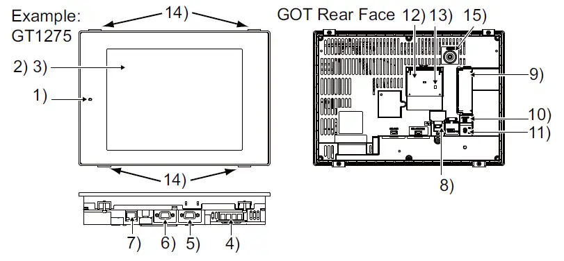
| No. | Name | Description |
| 1) | WER LED | Lit in green : Power is correctly supplied Lit in orange : Screen saving Blinks orange / green : Blown backlight bulb Not lit : Power is not supplied |
| 2) | Display sceen | Displays the Utility and user creation screen |
| 3) | Touch key | For operating touch switches in the Utility and the user creation screen |
| 4) | Power terminal | Power input terminal, LG terminal, FG terminal |
| 5) | RS-232 interface | For communicating with a controller or connecting a personal computer (Connector type: D sub 9-pin (male)) |
| 6) | RS-422/485 interface | For communicating with a controller (Connector type: D sub 9-pin (female)) |
| 7) | Ethernet interface | For communicating with a controller or using the FTP server function (Connector type: RJ-45 (modular jack)) |
| 8) | USB interface (Device) | For connecting a personal computer Connector type: MINI- B) |
| 9) | CF card interface | For installing a CF card |
| 10) | CF card access LED | Lit : CF card accessed Not lit : CF card not accessed |
| 11) | CF card access switch | Used for accepting or stopping the access to the CF card before removing the CF card from the GOT ON : CF card being accessed (CF card removal prohibited) OFF : CF card not accessed (CF card removal possible) |
| 12) | Battery holder | Houses the battery |
| 13) | Terminating resistor setting switch(Inside cover) | For switching on and off of the terminating resistor for the RS-422/485 communication port |
| 14) | Hole for unit installation fitting | Hole for inserting the unit installation fitting |
| 15) | Installation switch | Used for OS installations at the GOT startup |
SPECIFICATIONS
General Specifications
| Item | Specifications | ||||||
| Operating ambient temperature | Display section | 0 to 50 | |||||
| Other than the display section | 0 to 55 | ||||||
| Storage ambient temperature | -20 to 60 | ||||||
| Operating ambient humidity | 10 to 90% RH, non-condensing | ||||||
| Storage ambient humidity | 10 to 90% RH, non-condensing | ||||||
|
Vibration resistance | Compliant with JIS B 3502 and IEC 61131-2 | Frequency | Accele- ration | Half- amplitude | Sweep count | ||
| Under intermittent vibration | 5 to 9Hz | – | 3.5mm | 10 times each in X, Y and Z directions | |||
| 9 to 150Hz | 9.8m/s2 | – | |||||
| Under continuous vibration | 5 to 9Hz | – | 1.75mm | – | |||
| 9 to 150Hz | 4.9m/s2 | – | |||||
| Shock resistance | Compliant with JIS B 3502 and IEC 61131-2 (147 m/s2, 3 times each in X, Y and Z directions) | ||||||
| Operating atmosphere | No greasy fumes, corrosive gas, flammable gas, excessive conductive dust, and direct sunlight (Same as storage atmosphere) | ||||||
| Operating altitude*1 | 2000 m (6562 ft) max. | ||||||
| Installation location | Inside control panel | ||||||
| Overvoltage category*2 | II or less | ||||||
| Pollution degree*3 | 2 or less | ||||||
| Cooling method | Self-cooling | ||||||
| Grounding | D type grounding with a resistance of 100 or less, ground to panel when grounding is not possible | ||||||
- Do not use or store the GOT under pressure higher than the atmospheric pressure of altitude 0m (0ft.).
Failure to observe this instruction may cause a malfunction.
When an air purge is made inside the control panel by adding pressure, there may be a clearance between the surface sheet and the screen making it difficult to use the touch panel, or the sheet may come off. - This indicates the section of the power supply to which the equipment is assumed to be connected between the public electrical power distribution network a nd the machinery within the premises .tenor II applies to equipment for which electrical power is supplied from
fixed facilities.
The surge voltage withstand level for up to the rated voltage of 300 V is 2500 V. - This index indicates the degree to which conductive material is generated in the environment where the equipment is used.
In pollution degree 2, only non-conductive pollution occurs but temporary conductivity may be produced due to condensation.
| Point | |
| Refer to GT12 Supplementary Description for details on the performance specifications of each GOT. | |
Power Supply Specifications
The following indicates the power supply specifications for GT12.
- For GOTs powered from the 100 to 240VAC power supply
- For GOTs powered from the 24VDC power supply
| Note | |
Operation at momentary failure
| |
For GOTs powered from the 100 to 240VAC
power supply
| Item | Specifications | |
| GT1275-VNBA, GT1265-VNBA | ||
| Input power supply voltage | AC100 to 240VAC (+10%, -15%) | |
| Input frequency | 50/60Hz 5% | |
| Input max. apparent power | 44VA (maximum load) | |
| Power consumption | 18W or less | |
| When backlight is not lit | 15W or less | |
| Inrush current | 40A or less (4ms) (maximum load) | |
| Allowable momentary power failure time | 20 ms or less (AC 100VAC or more) | |
| Noise immunity | 1,500Vp-p noise voltage, 1 s noise width (when measuring with a noise simulator under 25 to 60Hz noise frequency) | |
| Dielectric withstand voltage | 1500VAC for 1 minute across power terminals and earth | |
| Insulation resistance | 10M or more across power terminals and earth by a 500V DC insulation resistance tester | |
| Applicable wire size | 0.75 to 2[mm2] | |
| Applicable solderless terminal | Solderless terminal for M3 screw RAV1.25-3, V2-S3.3, V2- N3A, FV2-N3A | |
| Applicable tightening torque (Terminal block terminal screw) | 0.5 to 0.8[N•m] | |
For GOTs powered from the 100 to 240VAC
power supply
| Item | Specifications | |
| GT1275-VNBD, GT1265-VNBD | ||
| Input power supply voltage | DC24V (+25%, -20%) | |
| Power consumption | 11W or less | |
| When backlight is not lit | 6W or less | |
| Inrush current | 29A or less (10ms) (maximum load) | |
| Allowable momentary power failure time | 10 ms or less | |
| Noise immunity | 500Vp-p noise voltage, 1 s noise width (when measuring with a noise simulator under 25 to 60Hz noise frequency) | |
| Dielectric withstand voltage*1 | 500VDC for 1 minute across power terminals and earth | |
| Insulation resistance*1 | 10M or more across power terminals and earth by a 500V DC insulation resistance tester | |
| Applicable wire size | 0.75 to 2[mm2] | |
| Applicable solderless terminal | Solderless terminal for M3 screw RAV1.25-3, V2-S3.3, V2- N3A, FV2-N3A | |
| Applicable tightening torque (Terminal block terminal screw) | 0.5 to 0.8[N•m] | |
- In this product, the surge absorber is connected between the power supply and the ground to avoid a malfunction due to noise caused by the application of lightning surge.
The values of the dielectric withstand voltage and insulation resistance are recorded when the surge absorber is not connected
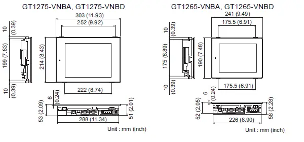
External Dimensions
EMC AND LOW VOLTAGE DIRECTIVE
For the products sold in European countries, the conformance to the EMC
Directive, which is one of the European Directives, has been a legal obligation since 1996. Also, conformance to the Low Voltage.
Directive, another European Directives, has been a legal obligation since 1997.
Manufacturers who recognize their products must conform to the EMC and Low Voltage Directive are required to declare that their products conform to these Directives and put a “CE mark” on their products.
- Authorized representative in Europe
Authorized representative in Europe is shown below.
Name :Mitsubishi Electric Europe BV
Address :Gather stares 8, 40880 Ratingen, Germany
Requirements to Meet EMC Directive
EMC Directives are those which require “any strong electromagnetic forceis not output to the external.:Emission (electromagnetic interference)” and
“It is not influenced by the electromagnetic wave from the external.:
Immunity (electromagnetic sensitivity)”.
- Items
- through
- summarize the precautions to use GOT and configure the mechanical unit in order to match the EMC directives.
Though the data described herein are produced with our best on the basis of the requirement items and standards of the restrictions gathered by
Mitsubishi, they do not completely guaranteed that all mechanical unit manufactured according to the data do not always match the above
directives. The manufacturer itself which manufactures the mechanical unit must finally judge the method and others to match the EMC directives.
EMC directive
The standards of the EMC Directive are shown below.
| Applied standard | Test standard | Test details | Standard value |
| EN 61131-2 : 2007 | EN55011 Radiated noise*1 | Electromagnetic emissions from the product are measured. | 30M-230MHz QP: 30dB V/m (30m in measurement range)*2, *3 230M-1000MHz QP: 37dB V/m(30m in measurement range)*2, *3 |
| EN55011 Conducted noise*1 | Electromagnetic emissions from the product to the power line is measured. | 150k-500kHz QP:79dB, Mean: 66dB*2 500k-30MHz QP:73dB, Mean: 60dB*2 | |
| EN61000-4-2 Electrostatic immunity*1 | Immunity test in which static electricity is applied to the cabinet of the equipment. | 4kV Contact discharge 8kV Aerial discharge | |
| EN61000-4-3 Radiated electro- magnetic field AM modulation | Immunity test in which field is irradiated to the product. | 80-1000MHz:10V/m 1.4-2GHz:3V/m 2.0-2.7GHz:1V/m 80%AM modulation@1kHz | |
| EN61000-4-4 Fast transient burst noise*1 | Immunity test in which burst noise is applied to the power line and signal lines. | Power line:2kV Digital I/O(24V or higher): 1kV (Digital I/O(24V or less))> 250V (Analog I/O, signal lines)> 250V | |
| EN61000-4-5 Surge immunity*1 | Immunity test in which lightening surge is applied to the product. | AC power type Power line (between line and ground): 2kV Power line (between lines): 1kV Data communication port: 1kV DC power type Power line (between line and ground): 0.5kV Power line (between lines): 0.5kV Data communication port: 1kV |
| Applied standard | Test standard | Test details | Standard value |
| EN 61131-2 : 2007 | EN61000-4-6 Conducted RF immunity*1 | Immunity test in which a noise inducted on the power and signal lines is applied. | Power line: 10V Data communication port: 10V |
| EN61000-4-8 Power supply frequency magnetic field immunity | Test for checking normal operations under the circum- stance exposed to the ferromagnetic field noise of the power supply frequency (50/60Hz). | 30 A/m | |
| EN61000-4-11 | Test for checking normal operations at instantaneous power failure. | AC power type 0.5 cycle 0% (interval 1 to 10s) 250/300 cycle 0% 10/12 cycle 40% 25/30 cycle 70% DC power type 10ms (interval 1 to 10s) |
- The GOT is an open type device (device installed to another device) and must be installed in a conductive control panel.
The above test items are conducted in the condition where the GOT is installed on the conductive control panel and combined with the Mitsubishi PLC. - QP (Quasi-Peak): Quasi-peak value, Mean: Average value
- The above test items are conducted in the following conditions.
30M-230MHz QP : 40dB V/m (10m in measurement range)
230M-1000MHz QP : 47dB V/m (10m in measurement range)
Control panel
The GOT is an open type device (device installed to another device) and must be installed in a conductive control panel.
It not only assure the safety but also has a large effect to shut down the noise generated from GOT, on the control panel.
- Control Panel
- The control panel must be conductive.
- When fixing a top or bottom plate of the control panel with bolts, do not coat the plate and bolt surfaces so that they will come into contact.
And connect the door and box using a thick grounding cable in
order to ensure the low impedance under high frequency. - When using an inner plate to ensure electric conductivity with the control panel, do not coat the fixing bolt area of the inner plate
and control panel to ensure conductivity in the largest area as possible. - Ground the control panel using a thick grounding cable in order to ensure the low impedance under high frequency.
- The diameter of cable holes in the control panel must be 10cm (3.94in.). In order to reduce the chance of radio wavesleaking out, ensure that the space between the control panel and its door is small as possible.
Paste the EMI gasket directly on the painted surface to seal the space so that the leak of electric wave can be suppressed.
Our test has been carried out on a panel having the damping characteristics of 37dB max. and 30dB mean (measured by 3m method with 30 to 300MHz
- Connection of power and ground wires Ground and power supply wires for the GOT must be connected as described below.
- Provide a grounding point near the GOT. Short-circuit the LG and FG terminals of the GOT (LG: line ground, FG: frame ground) and ground them with the thickest and shortest wire possible (The wire length must be 30cm (11.81in.) or shorter.)
The LG and FG terminals function is to pass the noise generated in the PC system to the ground, so an impedance that is as low as possible must be ensured. As the wires are used to relieve the noise, the wire itself carries a large noise content and thus short wiring means that the wire is prevented from acting as an antenna.
Note) A long conductor will become a more efficient antenna at high frequency. - The earth wire led from the earthing point must be twisted with the power supply wires.
By twisting with the earthing wire, noise flowing from the power supply wires can be relieved to the earthing. However, if a filter is installed on the power supply wires, the wires and the earthing wire may not need to be twisted.
- Provide a grounding point near the GOT. Short-circuit the LG and FG terminals of the GOT (LG: line ground, FG: frame ground) and ground them with the thickest and shortest wire possible (The wire length must be 30cm (11.81in.) or shorter.)
Noise filter (power supply line filter)
The noise filter (power supply line filter) is a device effective to reduce conducted noise. Except some models, installation of a noise filter onto the power supply lines is not necessary. However conducted noise can be reduced if it is installed. (The noise filter is generally effective for reducing conducted noise in the band of 10MHz or less.) Usage of the following filters is recommended.
| Model name | FN343-3/01 | FN660-6/06 | ZHC2203-11 |
| Manufacturer | SCHAFFNER | SCHAFFNER | TDK |
| Rated current | 3A | 6A | 3A |
| Rated voltage | 250V | ||
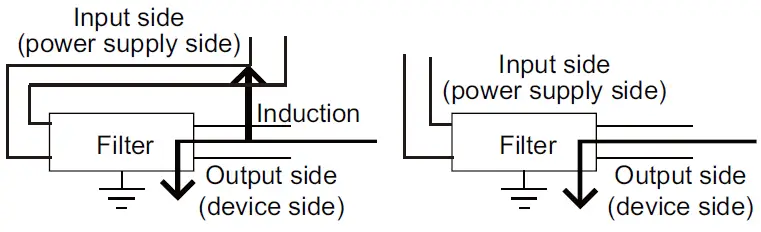
The precautions required when installing a noise filter are described below.
- Do not install the input and output cables of the noise filter together to prevent the output side noise will be inducted into the input able where noise has been eliminated by the noise filer.

- Connect the noise filter’s ground terminal to the control panel with the shortest cable as possible (approx. 10cm (3.94 in.) or less).
Requirements for Compliance with the Low
Voltage Directive
The Low Voltage Directive requires each device which operates with
power supply ranging from 50VAC to 1000V and 75VDC to 1500V to
satisfy necessary safety items.
In the Sections from 5.2.1 to 5.2.5, cautions on installation and wiring of the GOT to conform to the Low Voltage Directive requires are described.
We have put the maximum effort to develop this material based on the requirements and standards of the Directive that we have collected.
However, compatibility of the devices which are fabricated according to the contents of this manual to the above Directive is not guaranteed.
Each manufacturer who fabricates such device should make the final judgement about the application method of the Low
Voltage Directive
and the product compatibility.
Standard subject to GOT Power supply
The insulation specification of the GOT was designed assuming installation category II. Be sure to use the installation category II power supply to the GOT.
The installation category indicates the durability level against surge voltage generated by lightning strike.
Category II indicates a power supply whose voltage has been reduced by two or more levels of isolating transformers from the public power distribution
Control panel
Because the GOT is open type equipment (device designed to be stored within another device), be sure to use it only when installed in a control panel.
- Shock Protection
In order to prevent those who are unfamiliar with power facility, e.g., an operator, from getting a shock, make sure to take the following measures on the control panel.- Store the GOT within the control panel locked, and allow only those who are familiar with power facility to unlock the panel.
- Build the structure in order that the power supply will be shut off when the control panel is opened.
- Dustproof and waterproof features
The control panel also provides protection from dust, water and other substances. Insufficient ingression protection may lower the insulation withstand voltage, resulting in insulation destruction. - The insulation in the GOT is designed to cope with the pollution level 2, so use in an environment with pollution level 2 or better.
Grounding
The following are applicable ground terminals. Use them in the grounded state.
Be sure to ground the GOT for ensuring the safety and complying with the EMC Directive.
External wiring
- External devices
When a device with a hazardous voltage circuit is externally connected to the GOT, select a model which complies with the
Low Voltage Directive’s requirements for isolation between the primary and secondary circuits. - Insulation requirements
Dielectric withstand voltages are shown in the following table.
Reinforced Insulation Withstand Voltage
| Rated voltage of hazardous voltage area | Surge withstand voltage (1.2/50 s) |
| 150 VAC or below | 2500V |
| 300 VAC or below | 4000V |
EMC Directive-Compliant System
Configuration
GOT
Use any of the GOTs with which CE mark logo is printed on the rating plate.
All GT12 models support the EMC Directive.
Cables
Modify the cables (including user-produced cable) to ensure
compliance with the EMC Directive.
In addition, refer to the GOT1000 Series Connection Manual regarding cables to be used.
EMC Directive-Compliant System
Configuration
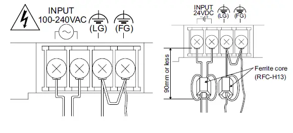
Wire and connect GOT1000 series equipment’s as instructed below.
For the GOT with the 24VDC power supply, attach a ferrite core (RFC-H13 manufactured by KITAGAWA INDUSTRIES CO.,LTD.)
within the range shown below.
If the GOT1000 series equipments are configured in a way different from the following instructions, the system may not comply with EMC directives.
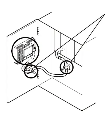
Power and ground wires wiring method
- Power and ground wires wiring method Connect the power wire and connection cable as shown in the
illustration.
Lead the power wire and ground wire as shown in Section 5.1.2 - Be sure to ground the LG cable, FG cable, and protective ground
Processing connection cables
Process the cable used with the GOT with the following method.
When processing the cable, ferrite core and cable clamp are required.
The cable clamp used by Mitsubishi Electric for the EMC specification
compatibility test is shown below.
- TDK corporation brand ZCAT3035-1330 Ferrite Core
- Mitsubishi Electric Model AD75CK cable clamp
- Japan Zipper Tubing Co., Ltd. Zipper tube SHNJ type
(1) CPU direct connection and computer link connection - Strip the outer insulation layer of the prepared cable by the length shown below to expose the braided shield for grounding. (For grounding with cable clamps.
For RS-232 cable
Ethernet connection
Strip the outer insulation layer at both ends of the cable by the length shown below to expose the braided shield for grounding.
(For grounding with cable clamps. (refer to Section 5.4.3.))
Attach the ferrite core to the cable in the position as illustrated below.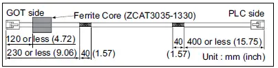 When connecting to PLC (manufactured by other company), microcomputer, temperature controller, inverter, servo amplifier, CNC, MODBUS(R)/RTU or MODBUS(R)/TCP connection.
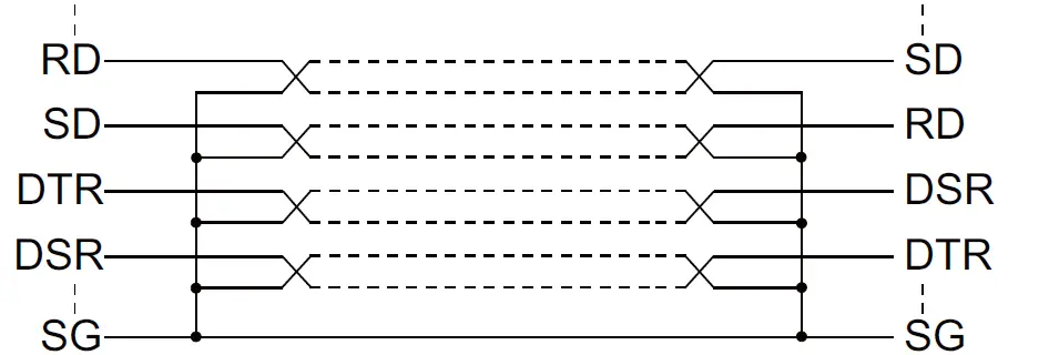
Produce the cable (RS-232 cable, RS-422 cable) for connecting the GOT to a controller with reference to the GOT1000 Series
Connection Manual.
| Point | |
| Configure the system to meet the EMC Directive specifications for the connected device when connecting the GOT to a controller. The following gives the instructions to ensure the machinery comply with the EMC Directive. However, the manufacturer of the machinery must finally determine how to make it comply with the EMC Directives: if it is actually compliant with the EMC Directives. | |
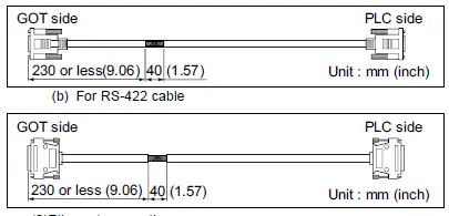
- (a) For RS-422/485 cable
- Each signal wire (excluding SG and FG) should be made into a two power wires and connected, then twisted.
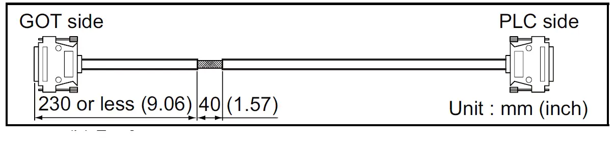
- For RS-232 cable
Use a twisted pair style for each signal wire (except SG, FG) with SG.
- Strip the outer insulation layer of the prepared cable by the length shown below to expose the braided shield for
grounding. (For grounding with cable clamps. (Refer to Section 5.4.3
Grounding the cable
- Ground the cable and grounding wire to the control panel where the GOT and base unit are installed
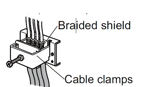
- Do not arrange the cable clamp adjacent to other cables which do not clamp.
- Noise from the control panel may access the GOT from the cable clamp and cause adverse effects.
INSTALLATION
Control Panel Inside Dimensions for Mounting GOT
Install the GOT on the control panel out of the way for the equipment
inside the control panel. Do not install the GOT and the unit in prohibited areas for the installation.
When mounting the GOT to the control panel, place the mounting fixtures (included with GOT) on the mounting fixture attaching part of the GOT, and fix them by tightening in the torque range of 0.36 to 0.48N•m.
| Point | |
| Applicable cable Some cables may need to be longer than the specified dimensions when connecting to the GOT. Therefore, consider the connector dimensions and bending radius of the cable as well for installation. | |
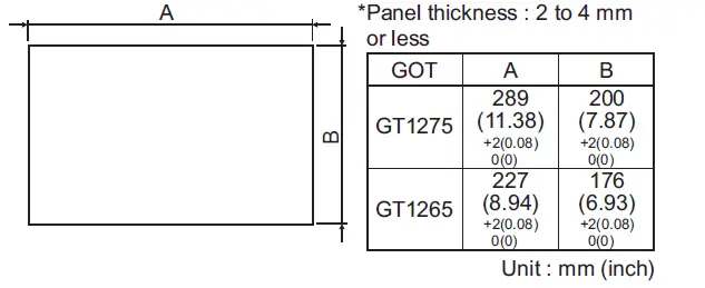
Panel Cutting Dimensions
Mounting Position
When mounting the GOT, the following clearances must be maintained from other structures and devices.
Some cables may need to be longer than the specified dimensions when connecting to the GOT.
Therefore, consider the connector dimensions and bending radius of the cable as well for installation.
For the lead-in allowance for cables at the bottom of the GOT, refer to the following
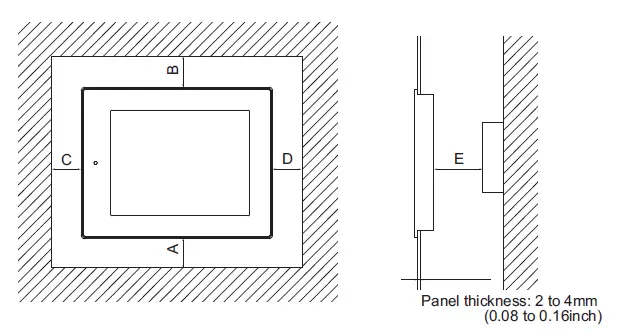
| Installation Environment | A,D | B | C | E | |
| When the CF card is not used | When the CF card is used | ||||
| In the presence of radiated-noise or heat-generating equipment nearby | 50(1.97) or more | 80(3.15) or more | 50(1.97) or more | 100(3.94) or more | 100(3.94) or more |
| In the absence of radiated-noise or heat-generating equipment nearby | 20(0.79) or more | 20(0.79) or more | 20(0.79) or more | 20(0.79) or more | |
SPECIFICATION FUNCTION
OMPARISON FOR GT12 AND GT11
The table overview shows the different specifications and functions available on the GT12 and the GT11.
For details of each function, refer to the relevant manual.
- Hardware comparison
The following shows the differences in hardware on the GT12 and the GT11
| Item | GT12 | GT11 | Relevant manual | |||||
| GT1275- VNBA | GT1275- VNBD | GT1265- VNBA | GT1265- VNBD | GT1155-QSBD | GT1155-QLBD | |||
| Display section | Type | TFT color liquid crystal display | STN color liquid crystal display | STN monochrome liquid crystal display (white/black) | GT11 User’s Manual (Hardware) | |||
| Screen size | 10.4″ | 8.4″ | 5.7″ | |||||
| Resolution | 640 ´ 480 [dots] | 320 ´ 240 [dots] | ||||||
| Display size | 211(8.31)(W) 158(6.22)(H) [mm](inch) | 171(6.73)(W) ´ 128(5.04)(H) [mm](inch) | 115(4.53)(W) ´ 86(3.39)(H) [mm](inch) | |||||
| Character display count | 16-dot standard font: 40 characters 30 lines (2byte character) 12-dot standard font: 53 characters 40 lines (2byte character) | 16-dot standard font: 20 characters 15 lines (2byte character) 12-dot standard font: 26 characters 20 lines (2byte character) | ||||||
| Color display | 256 colors | 256 colors | Monochrome (white/black) 16 Scales | |||||
| Display angle | Left/Right: 45 degrees Top/Bottom: 20 degrees | Left/Right: 50 degrees Top: 50 degrees Bottom: 60 degrees | Left/Right: 45 degrees Top: 20 degrees Bottom: 40 degrees | |||||
| Contrast adjustment | – | 16-level adjustment | ||||||
| Intensity of LCD only | 200[cd/m2] (Adjustable in 4 levels) | 380[cd/m2] (Adjustable in 8 levels) | 220[cd/m2] (Adjustable in 8 levels) | |||||
| Life | Approx. 52,000 h (Operating ambient temperature: 25 ) | Approx. 50,000 h (Operating ambient temperature: 25 ) | ||||||
| Backlight | Life | Approx. 50,000 h or longer(Time when display luminance reaches 50% at the operating ambient temperature of 25 ) | Approx. 40,000 h or longer(Time when display luminance reaches 50% at the operating ambient temperature of 25 ) | Approx. 75,000 h or longer | Approx. 54,000 h or longer | |||
| Touch panel | Type | Analog resistive film | Matrix resistive film | GT16 User’s Manual (Hardware) GT11 User’s Manual | ||||
| Number of touch keys | – | 300 keys/screen (Matrix structure of 15 lines ´ 20 columns) | ||||||
| Key size | Minimum 2 ´ 2 [dots] (per key) | Maximum 16 ´ 16 [dots] (per key) | ||||||
| Number of objects that can be simultaneously touched | Simultaneous presses not allowed. (Only 1 point can be touched.) | Maximum of 2 points | ||||||
| Memory | C drive | Built-in flash memory 9MB*1 | Built-in flash memory 3MB | GT11 User’s Manual | ||||
| Built-in interface | USB (device) | (Rear side) | (Front side) | |||||
| Option function board | Option functions supported as standard | Option function board is necessary for option function use | ||||||
| Ethernet | GT16 User’s Manual (Hardware) | |||||||
| Item | GT12 | GT11 | Relevant manual | ||||
| GT1275- VNBA | GT1275- VNBD | GT1265- VNBA | GT1265- VNBD | GT1155-QSBD | GT1155-QLBD | ||
| External dimensions | 303(11.93)(W) ´ 214(8.43)(H) ´ 53(2.09)(D) | 241(9.49)(W) ´ 190(7.48)(H) ´ 58(2.29)(D) | 164(6.46)(W) ´135(5.32)(H) ´ 56(2.21)(D) [mm](inch) | ||||
| [mm](inch) | [mm](inch) | ||||||
| 289(11.38)(W) ´ | 227(8.94)(W) ´ | 153 (6.03)(W) ´ 121(4.77)(H) [mm] (inch) | |||||
| Panel cutting dimensions | 200(7.87)(H) [mm](inch) | 176(6.93)(H) [mm](inch) | GT11 User’s Manual | ||||
| Weight (mounting fixtures are | 2.3kg(5.1lb) | 1.7kg(3.7lb) | 0.7kg(1.5lb) | ||||
| not included) | |||||||
| Power supply | 100 to | 24VDC | 100 to | 24VDC | DC24V | ||
| 240VAC | 240VAC | ||||||
| Item | GT12 | GT11 |
Relevant manual | ||
| GT1275-VNBA, GT1275-VNBD | GT1265-VNBA, GT1265-VNBD | GT1155-QSBD, GT1155-QLBD | |||
| Protective sheet | Clear | GT11-70PSCB | GT11-60PSCB | GT11-50PSCB | GT11 User’s Manual |
| Antiglare | ´ | GT11-50PSGB | |||
| Clear (Frame: white) | ´ | GT11-50PSCW | |||
| Antiglare (Frame: white) | GT11-50PSGW | ||||
| Battery | GT11- 50BAT | *1 | (Pre-attached for shipment) | ||
| Attachment | ´ | ´ | GT16 User’s Manual (Hardware) | ||
| GT15-70 ATT-87 | ´ | ´ | |||
| GT15-60 ATT-97 | ´ | ´ | |||
| GT15-60 ATT-96 | ´ | ´ | |||
| GT15-60 ATT-87 | ´ | ´ | |||
| GT15-60 ATT-77 | ´ | ´ | |||
| Stand | GT15-70STAND | GT05-50STAND | GT16 User’s Manual (Hardware) GT11 User’s Manual | ||
| Backlight | GT12-70VLTN | GT12-60VLTN | Replacement unavailable | ||
- The GOT automatically formats the D drive (SRAM) when the battery is not attached.
Attach the battery to keep clock and alarm history data - Function comparison
The following shows the differences in functions on the GT12 and the GT11.
For details of the utility screen, refer to the GT16 User’s Manual
| Item | GT12 | GT11 | Relevant manual | |
| GT1275-VNBA, GT1275-VNBD, GT1265-VNBA, GT1265-VNBD | GT1155-QSBD, GT1155-QLBD | |||
| Shape | Rounded, rectangle | Screen Design Manual (Fundamentals) | ||
| GOT internal device | GB | 65536 points | 65536 points | |
| GD | 65536 points | 65536 points | ||
| Vertical format | ||||
| Screen changing | Memory card storage for screen transition history | |||
| ASCII input/display | Text alignment | Screen Design Manual (Functions) | ||
| Historical data list display | Maximum number of objects per screen | 1 | ||
| Date display/time display | View format | Date: 20 types Time: 6 types | Date: 20 types Time: 6 types | |
| User alarm | Alarm (device) points | Maximum 8192 | Maximum 8192 | |
| Alarm history | Alarm (device) points | 3072 | 3072 | |
| Alarm history recorded | D drive: 2048 records A drive: 3072 records | D drive: 2048 records A drive: 3072 records | ||
| File storage location | D drive, A drive | D drive, A drive | ||
| Alarm display function | Popup display | Scrolling display | ||
| Advanced alarm observation | ||||
| Advanced user alarm function | D drive, A drive (Number of alarms : 8) | ´ | ||
| Advanced system alarm function | D drive, A drive | ´ | ||
| Line graph | Scale points | 101 | 101 | |
| Trend graph | Scale points | 101 | 101 | |
| Bar graph | Scale points | 101 | 101 | |
| Statistics bar graph | Scale points | 101 | 101 | |
| Statistics pie graph | Scale points | 101 | 101 | |
| Scatter graph | Scale points | 101 | 101 | |
| Circle graph | Scale points | 101 | 101 | |
| Item | GT12 | GT11 | Relevant manual | |
| GT1275-VNBA, GT1275-VNBD, GT1265-VNBA, GT1265-VNBD | GT1155-QSBD, GT1155-QLBD | |||
| Historical trend graph | ´ |
Screen Design Manual (Functions) | ||
| Points | 300 points | – | ||
| Number of pens | 8 lines | – | ||
| Number of objects on a screen | 1 | – | ||
| Logging function | ´ | |||
| Cycle (logging trigger) | 500ms (minimum value) | – | ||
| Number of settings | 4 | |||
| Recipe function | 1 | 1 | ||
| Recipe count | 8192 points is total for all recipe settings | 8192 points per 1 recipe setting | ||
| Recipe file storage location | D drive, A drive | D drive, A drive | ||
| Bar code function | ||||
| RFID function | ||||
| Hard copy function*2 | ||||
| Hard copy file storage location | A drive | |||
| Maximum number of files | 100 | |||
| FA transparent function | GT16 User’s Manual | |||
| GOT maintenance function | GOT start time | |||
| Multi-channel function | (Maximum 2 Ch.) | |||
| FTP server function | Gateway Functions Manual | |||
| System monitoring function | GOT1000 Series User’s Manual (Extended Functions, Option Functions) | |||
| A list editor function | *1 | *1 | GOT1000 Series User’s Manual (Extended Functions, Option Functions) | |
| FX list editor function | *1 | *1 | ||
| Back-up/restore function | ´ | GOT1000 Series User’s Manual (Extended Functions, Option Functions) | ||
| GOT data package acquisition |
| ´ | ||
| Software package support | GT Designer3 English version: Version 1.01B or later | GT Designer3 Japanese version: Version 1.00A or later English version: Version 1.01B or later GT Designer2 Japanese version: Version 2.25B or later English version: Version 2.27D or later | ||
- An option function board is required for the GT11.
No option function board is required for the GT12. - When the file number is between 90 and 100, the system signal 2-1.b12 (hard copy auxiliary signal) turns on.
The signal notifies that the number of files in a CF card has reached almost the maximum (100).
GT Designer3 comparison
The following shows the differences in settings for GT Designer3 on the GT12 and the GT11.
When designing GT12 screens, BMP and JPEG format files can be used for parts display and parts movement images
| Item | GT12 | GT11 | Relevant manual | ||
| Model setting |
GOT type | Model | GT12**-V(640´480) | GT11**-Q(320´240) | Screen Design Manual (Fundamentals) |
| Setting /installation direction | Horizontal and vertical option not available | Horizontal and vertical option available | |||
| Color setting | 256 colors | Monochrome 16 adjustment level, 256 colors | |||
| Connection device setting | CH1 | I/F | Standard I/F(RS422/485) Standard I/F(RS232) Standard I/F(Ethernet) | Standard I/F(RS422/232) Standard I/F(RS232) | |
| CH2 | I/F | Standard I/F(RS422/485) Standard I/F(RS232) Standard I/F(Ethernet) | I/F none | ||
GT Simulator3 comparison
The following shows the differences in functions for [GOT1000 series GT12 simulator] and [GOT1000 series GT11 simulator] on GT Simulator3.
To use the GT12 simulation functions on GT Simulator3, select [GOT1000 series GT12 simulator] in the main menu dialog box on GT Simulator3.
If no differences exist in the simulation function for [GOT1000 series GT12 simulator] and [GOT1000 series GT11 simulator] on GT Simulator3, the specifications are the same as that for the hardware.
For details of the hardware specifications, refer to the following.
- Hardware comparison
- Function comparison
For details of the functions and the utility to operate the GT12, refer to the following.
GT Simulator3 Version1 Operating Manual for GT Works3 (3.2 Functions that cannot be simulated)
| Item | GOT1000 series (GT12) simulator | GOT1000 series (GT11) simulator | Relevant manual | ||
| Option | Action setup | GOT type | GT12**-V | GT11**-Q | GT Simulator3 Version1 Operating Manual for GT Works3 |
| Resolution*1 | 640 ´ 480 [dots] | 320 ´ 240 [dots] | |||
| Color display*1 | 256 colors | 256 colors | |||
| Memory*1 | 9MB | 3MB | |||
| Advanced alarm observation | *2 | ´ | |||
| Historical trend graph | *2 | ´ | |||
| Logging function | *2 | ´ | |||
| Hard copy function | 2 | ´ | |||
| Software package support*3 | GT Designer3 English version: Version 1.14Q or later | GT Designer3 English version: Version 1.01B or later | |||
- For details of the specifications, refer to (1) Hardware comparison.
- For details of the functions, refer to (3) Function comparison.
- GT Simulator3 is installed or uninstalled automatically when GT Designer3 is installed or uninstalled
Installation comparison
The installation method of the GT12 is the same as that for the GT1155.
For details of the installation, refer to the following.
GT11 User’s Manual
Wiring comparison
Use the same wiring methods of GT16 to configure the GT12 wirings.
For details of the wiring, refer to the following.
GT16 User’s Manual (Hardware)
Utility function comparison
The operation method of the utility function of the GT12 is the same as that for the GT16.
For details on the operation method of the utility function, refer to the following.
GT16 User’s Manual (Basic Utility)
Message displaying language selectable by utility
For the GT12, the message displaying language selectable by the utility is the same as that for the GT11.
For details of the relationship between the message displaying language selectable by the utility and the standard font, refer to
the following.
GT Designer3 Version1 Screen Design Manual (Fundamentals)
Warranty
Mitsubishi will not be held liable for damage caused by factors found not to be the cause of Mitsubishi; machine damage or lost profits caused by faults in the Mitsubishi products; damage, secondary damage, accident compensation caused by special factors
unpredictable by Mitsubishi; damages to products other than Mitsubishi products; and to other duties.
For safe use
- This product has been manufactured as a general-purpose part for general industries, and has not been designed or manufactured to be incorporated in a device or system used in purposes related to human life.
- Before using the product for special purposes such as nuclear power, electric power, aerospace, medicine or passenger movement vehicles, consult with Mitsubishi.
- This product has been manufactured under strict quality control.
However, when installing the product where major accidents or losses could occur if the product fails, install appropriate backup or failsafe functions in the system.
Country/Region Sales office/Tel
USA Mitsubishi Electric Automation, Inc.
500 Corporate Woods Parkway, Vernon Hills, IL 60061, U.S.A.
Tel: +1-847-478-2100


