salicru EQX 5000-2T Equinox Solar Inverters
CONTENTS
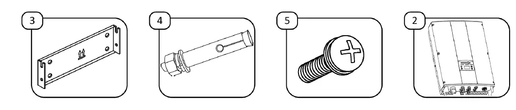
Make sure all of the following items are inside the box: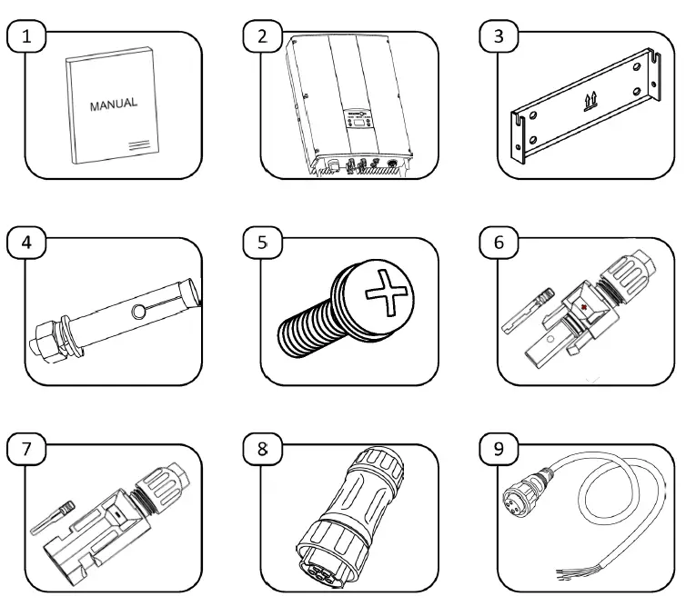
| Item | Description | Quantity |
| 1 | Quick guide | 1 |
| 2 | Equinox solar inverter | 1 |
| 3 | Wall mount | 1 |
| 4 | Metal bolt (only for concrete walls) | 4 |
| 5 | Fixing screws | 2 |
| 6 | POSITIVE DC connector set and terminal | 2 |
| 7 | NEGATIVE DC connector set and terminal | 2 |
| 8 | AC connector | 1 |
| 9 | RS485 communications connector | 1 |
If anything is missing, contact your supplier in order to return this device and arrange for a new one, containing all of the listed items, to be delivered.
MECHANICAL INSTALLATION.
POSITIONING THE DEVICE
If you are installing the optional ESM3T EQX energy meter, we recommend installing the inverter as near to the electrical connection as possible, in order to avoid extending the RS485 communications cable.
Angle and spacing of the installation: Make sure the device is installed on a vertical surface and that the following minimum safety distances are maintained with regard to other elements, in order to ensure optimum ventilation: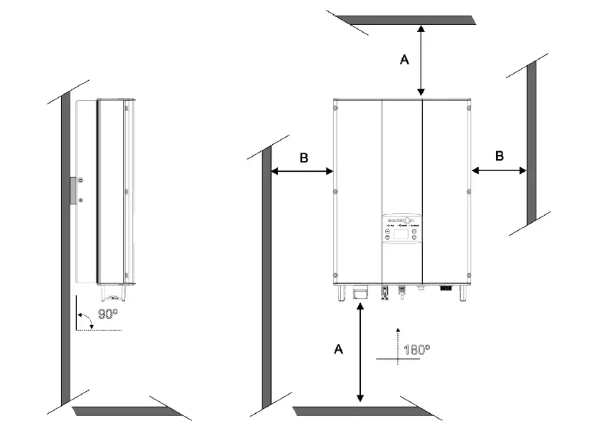
| Dimension | Distance (mm.) |
| A | 500 |
| B | 400 |
Wall mount: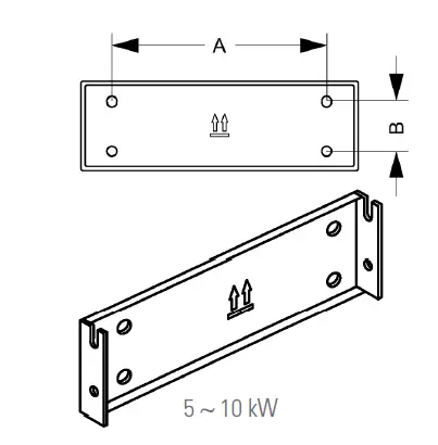
| Model | A (mm) | B (mm) | Ø (mm) | Drill depth (mm) | Tightening torque (Nm) |
| EQX 5000-2T | 260 | 45 | 8 | 50 | 13 |
| EQX 8000-2T | |||||
| EQX 10000-2T |
Mounting process
Material required
Steps to follow: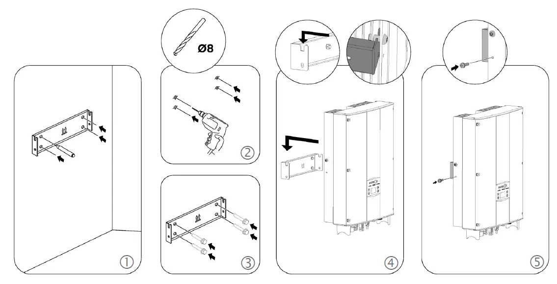
ELECTRICAL INSTALLATION
DC (DIRECT CURRENT) INSTALLATION
Make sure the inverter’s isolator switch is in the OFF position.
Make sure the protection systems in the junction box are activated and that there is no voltage in the cables you are going to handle.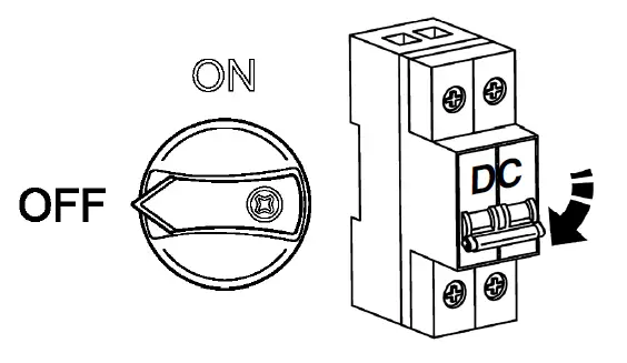
Connecting the solar park cables:
Material required: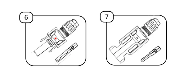
- Unscrew the MC4 connectors (supplied) and prepare the cables coming from the junction box of the solar park:

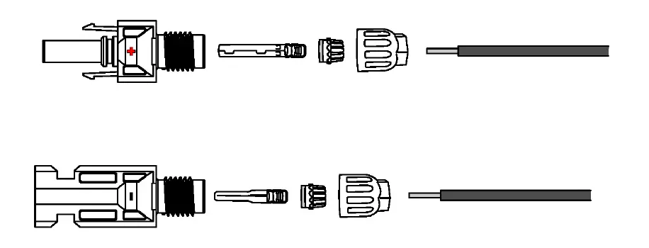
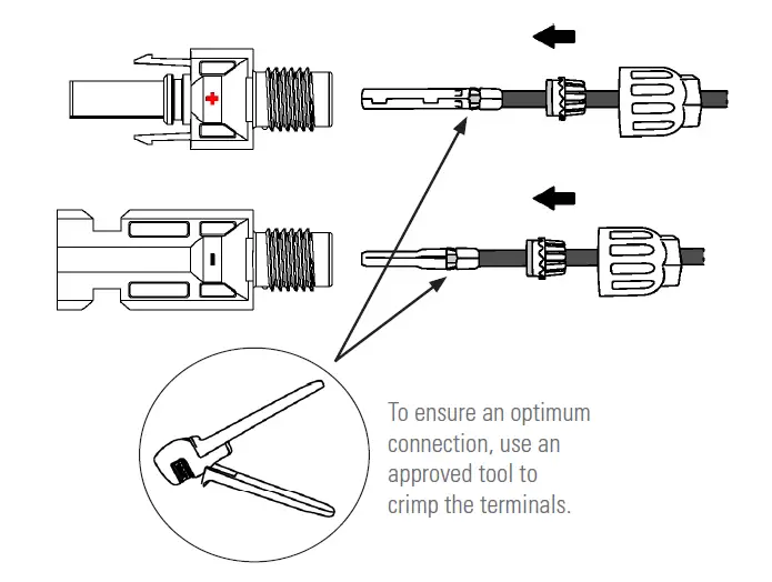
- Pass the cables through the screw caps, crowns and rubber seals, as shown below. Then crimp the metal terminals to the cables.

- Insert the metal terminals into the MC4 connectors, until you hear a click. Once this is done, pull gently on the cable to make sure it is correctly attached.
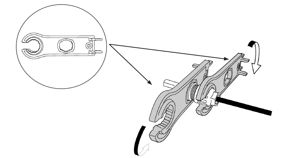
- Screw the cap onto the body of each connector, making sure all of the elements fit together perfectly and that the rubber seals seal the cable with the connector:

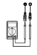
Use the special spanners for MC4 connectors in order to ensure optimum tightening without damaging the connectors. - Check the polarity and voltage of the photovoltaic panels before connecting them to the inverter, in line with the values shown in the following table:

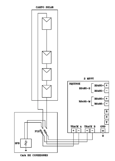
Specifications Inverter model EQX 5000-2T EQX 8000-2T EQX 10000-2T Maximum DC input power (W) 5500 8800 11000 Maximum DC input voltage (VDC) 900 1000 Operating range (VDC) 200-800 MPPT range (VDC) 260-800 350-800 400-800 MPPT trackers / inputs per MPPT 2/1 Max. input current per MPPT x no. of MPPTs 10 A x 2 12 A x 2 12,5 A x 2 Max. short-circuit current per MPPT (Isc PV) x no. of MPPTs 11 A x 2 13 A x 2 14 A x 2 - Connect the cables to the inverter in accordance with the following connection diagrams:
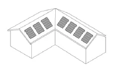
Connection process for facilities with solar parks of varying power (panels with different orientations and/or strings of different lengths): If the facility’s solar panels are not on the same level, i.e. they are exposed to different levels of radiation (whether due to the shape of the roof, differences in inclination, or different string lengths), the connection process must be carried out as follows:
The devices allow for a maximum solar power imbalance of 40%-60%.
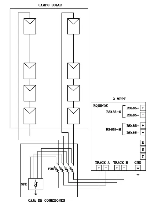
Connection process for facilities with a single solar park (i.e. panels with the same orientation and strings of the same length):
For facilities where all of the power is in the same solar park, the power must be distributed between the two tracks, joining both inverter inputs as shown in the diagram below:
This configuration requires modification of the “Adjust Model” parameter on the device. Refer to the section titled “Changing the MPPT Model” (Page 17).
 If the facility’s solar panels are not on the same level, i.e. they are exposed to different levels of radiation (whether due to the shape of the roof, differences in inclination, or different string lengths), the connection process must be carried out as follows:
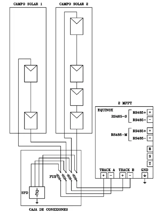
Strings that can be connected to each MPPT, depending on the device model:
| Model | String / MPPT |
| EQX 5000-2T | 1/2 |
| EQX 8000-2T | 1/2 |
| EQX 10000-2T | 1/2 |
AC (ALTERNATING CURRENT) INSTALLATION
Make sure the protection systems in the junction box are activated and that there is no voltage in the cables you are going to handle.
If you are installing the optional ESM3T EQX energy meter, we recommend installing the inverter as near to the electrical connection as possible, in order to avoid extending the RS485 communications cable.
Material required:
Connecting the network cables
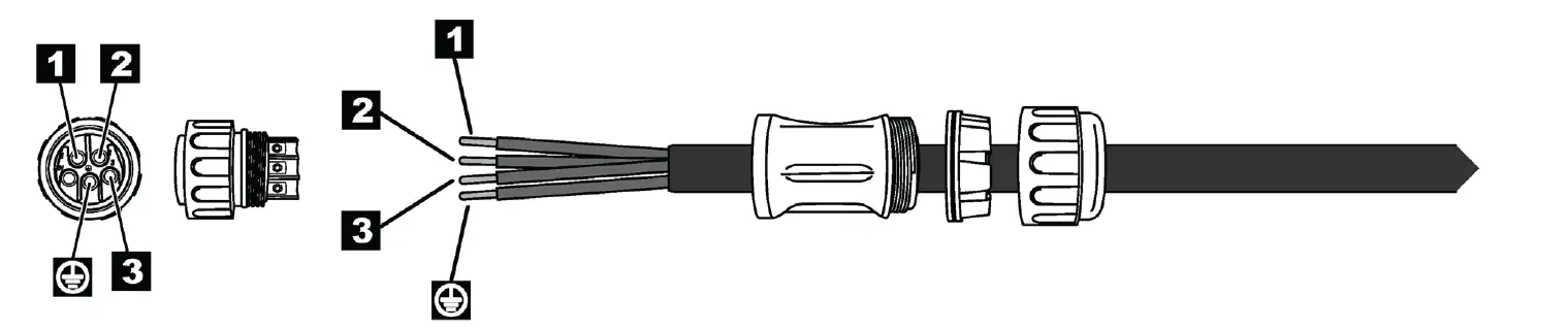
- Unscrew the AC connector (supplied) and prepare the cables coming from the junction box of the power supply:

- Pass the cables through the screw cap, crown and rubber seal, as shown below. To optimise the connection, we recommend crimping the terminals at the ends of the cables.

- Insert and screw the cables to the corresponding terminals on the connector: R phase, S phase, T phase and earth (G). Once this is done, pull gently on the cables to make sure they are firmly attached.
- Connect the sleeve to the inverter’s AC connector.
- Connect the other end of the sleeve to the AC protection in the junction box.
- Connect the AC part of the junction box downstream of the main automatic circuit breaker for the power supply.

- Connection diagram:


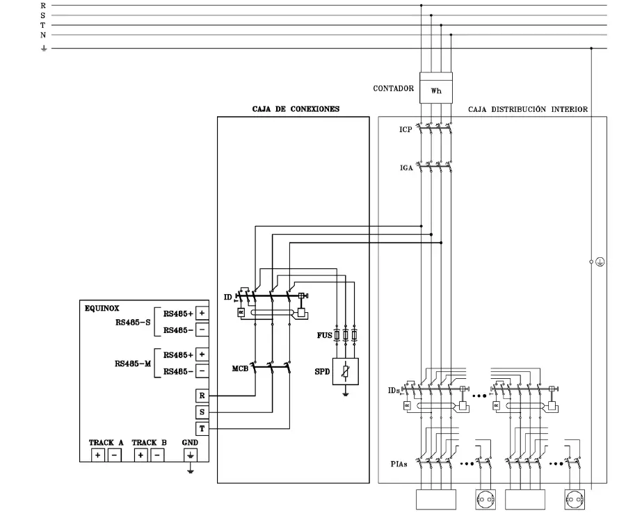
JUNCTION BOX
The junction box must incorporate all of the additional protective elements (both AC and DC) that are required in order to protect the inverter once it has been installed.
The protective DC elements that must be incorporated into the junction box are as follows:
| Model | Isolator switch | Fuses | Overvoltage protector | |
| If there is no lightning conductor | If there is a lightning conductor or a high probability of lightning strike | |||
| EQX 5000-2T | Built into the device | Fuses: 1000 VDC 15 A / string | Type II, 40 kA 1000 VDC | Type I+II, 5 kA 1000 VDC |
| EQX 8000-2T | Built into the device | Fuses: 1000 VDC 15 A / string | Type II, 40 kA 1000 VDC | Type I+II, 5 kA 1000 VDC |
| EQX 10000-2T | Built into the device | Fuses: 1000 VDC 15 A / string | Type II, 40 kA 1000 VDC | Type I+II, 5 kA 1000 VDC |
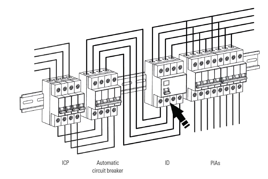
The AC elements required are as follows (and must also be physically separated):
| Model | Circuit breaker | Residual-current device | Overvoltage protector | Pre-fuses. Maximum value (x 3) |
| EQX 5000-2T | 3P 10 A Curve C | 4P 25 A 30 mA Class A | Type II, 40 kA 400 V TNC | 125 A gL |
| EQX 8000-2T | 3P 16 A Curve C | 4P 25 A 30 mA Class A | Type II, 40 kA 400 V TNC | 125 A gL |
| EQX 10000-2T | 3P 16 A Curve C | 4P 25 A 30 mA Class A | Type II, 40 kA 400 V TNC | 125 A gL |
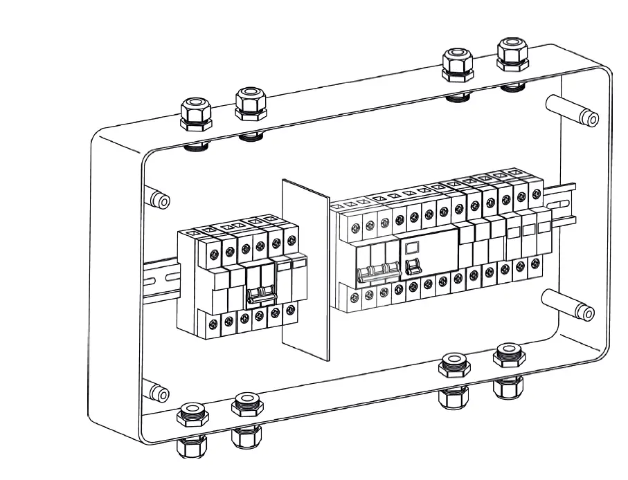
Example of a junction box with DC protections on the left and AC protections on the right.
ON/OFF SEQUENCE
Danger of electric arc. Do not open any DC isolator switches if the device is charging.
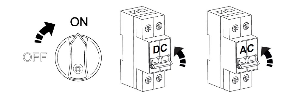
Follow the steps below in order to start up the inverter:
- Activate the inverter’s isolator switch and place it in the ON position.
- Make sure the solar park is connected. Activate the protections in order to enable the photovoltaic supply.
- Make sure there is mains voltage. Activate the protections in order to enable the mains supply. Without a mains supply, the device will not enter generation mode.

- The device will start up. The LCD screen will turn on. The following section details the steps to follow and explains how the console works.
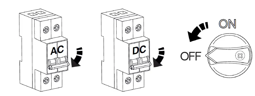
Follow the steps below in order to stop the inverter and switch it off:- Shut off the mains power supply. Without a mains supply, the device will stop generating.
- Shut off the solar park power supply. Activate the protections in order to shut off the photovoltaic supply.
- Deactivate the inverter’s isolator switch and place it in the OFF position.

- The device will stop. When the internal capacitors of the DC bus are without voltage, the LCD screen will turn off.
OPERATION USING THE DISPLAY
DISPLAY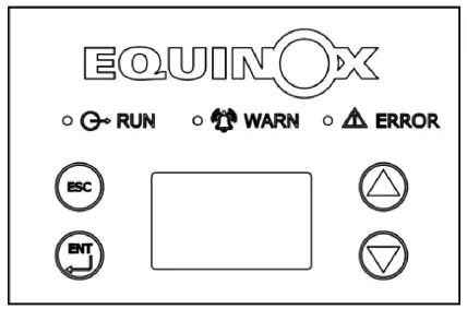
The buttons are operated by touch. Take care not to activate any functions accidentally.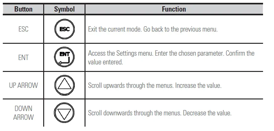
The first time power is supplied to the inverter, the screen will directly display the Quick Settings menu, the language selection and the country of installation.
PARAMETERS MENU
Your new EQUINOX solar inverter comes pre-configured to comply with the current Spanish regulations. Therefore, you only have to configure the parameters for the date, time and price per kWh in order to obtain an approximate estimate of the savings to be made.
Press the ENT button to access the main menu. Press the DOWN ARROW to scroll through the menus until you reach the SETUP MENU sub-menu. Press the ENT button to access it. You will be asked to enter a password. Refer to the section titled “Entering Passwords” (Page 18) and enter the number 2012.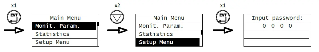
Setting the price per kWh
After you have entered the password, you can access the SETUP MENU sub-menu. Press the DOWN ARROW to scroll through the menus until you reach the CASH/PRICE sub-menu. Press the ENT button to access it. Use the ENT button to confirm that the chosen currency is the Euro (EUR) and set the approximate price per kWh, in accordance with your electricity tariff.
The example below shows how to set a value of €0.12 per kWh: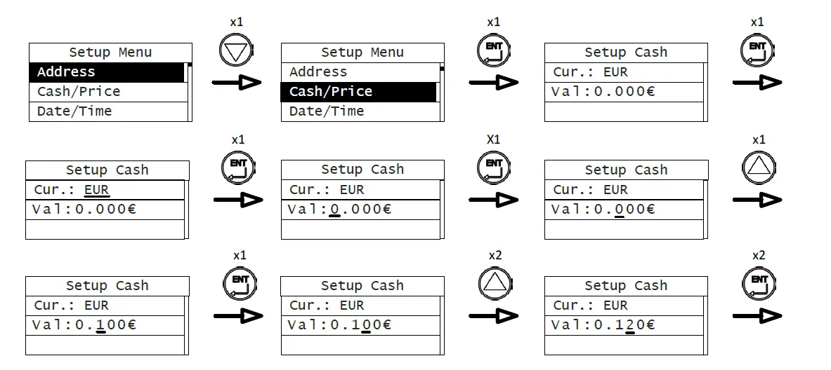
Setting the date and time:
Go back to the Settings menu. If you are already on a menu page, use the ESC button to exit. Then use the DOWN ARROW to scroll through the menus until you reach the DATE/TIME sub-menu. Press the ENT button to access it. Press the ENT button to start setting the date.
The example below shows how to set the date to 9 March 2025: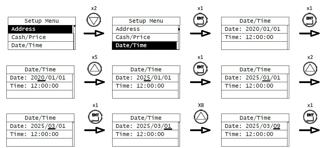
Now you must set the time. The example below shows how to set the time to 16:45:00: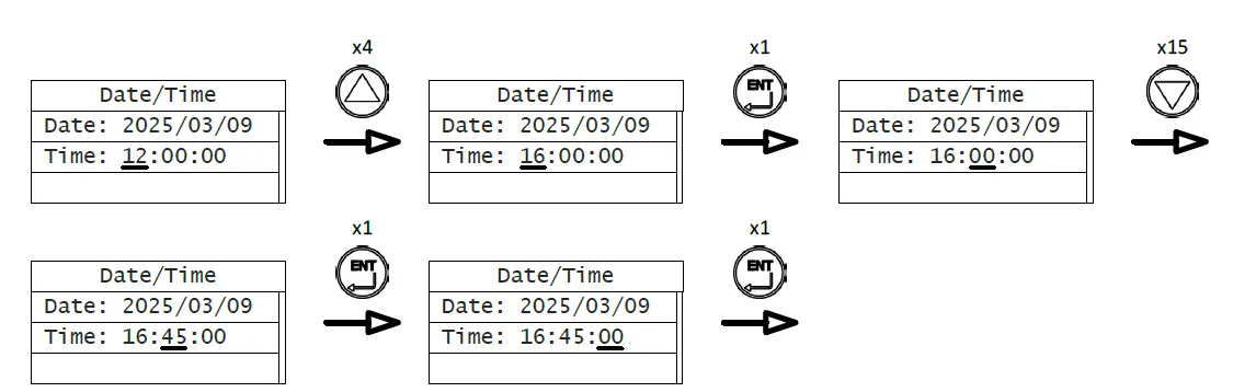
Changing the MPPT model
By default, the device is configured to connect 2 MPPTs. To change the configuration to 1 MPPT, go to the SET MODEL menu (within the Settings menu). Press the ENT button to access it. Press the DOWN ARROW to select the 1 MPPT option. Press the ENT button to confirm the selection.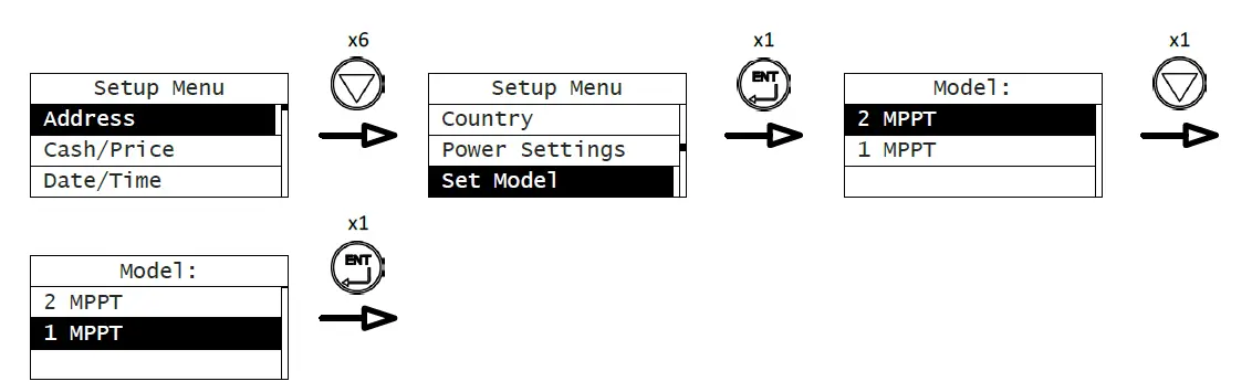
Entering passwords:
In order to prevent any unauthorised changes to the device’s settings, some menus require you to enter a password in order to access certain parameters. When a password is required, a screen similar to the one in the diagram below will appear, along with the text “Input Password”. If you press ENT, a line will appear below the first number. You can modify this number using the UP and DOWN ARROWS to enter the number of your choice. Press ENT again to confirm the number, and the line will then move on to the next number on the right.
The example below shows how to enter the password 2012: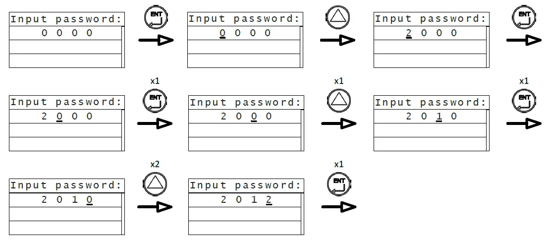
If the password entered is correct, the sub-menu will appear automatically. If the password is incorrect, the words “Error, again!” will appear.Press ENT to try again.
Monit. Param.
- E-Tod
- €-Tod
- P-In
- P-Out
- PpDay
- V-Out-R
- V-Out-S
- V-Out-T
- I-Out-R
- I-Out-S
- I-Out-T
- F-Grid
- PF
- V-Pv1
- I-Pv1
- V-Pv2
- I-Pv2
- R-Iso
- Ileak
- Temp1
- Temp2
- E-Tot
- H-Tot
- Date
- Time
- H-ON
- T-Tod
- H-PPk
- H-OFF
- U-OFF
Statistics
- Lifetime
- Run-T
- kWh
- Sav.
- CO2
- Today
- kWh
- PPk
- Sav.
- CO2
- Setup Menu
- Adress
- Cash/Price
- Cur.
- Val
- Date/Time
- Date
- Time
- Language
- Español
- `English
- Deutsch
- Duch
- Country
- Spain
- Germany
- UK
- Aus_default
- Belgium
- Denmark
- Holland
- Thailand
- Singapore
- Italy
- New Zealand
- Aus_Standard
- Power Settings
- Export P. Set.
- Lim. Inv. P.
- Power Factor
- Gr. Ti. Mode
- Factor
- Set Model
- 2 MPPT
- 1 MPPT
- ISO Check
- ISO Level
- AntiReflux
- 10min 0V
- Run Param.
- Aus Standard
- System Info.
- Part No.
- Serail No.
- System Ver.
- Cert. Area
- Run Param.
- U. V. Value 1
- U. V. Time 1
- O. V. Value 1
- O. V. Time 1
- Min. F. v. 1
- Min. F. T. 1
- Max. F. v. 1
- Max. F. T. 1
- U. V. Value 2
- U. V. Time 2
- O. V. Value 2
- O. V. Time 2
- Min. F. v. 2
- Min. F. T. 2
- Max. F. v. 2
- Max. F. T. 2
- Restart Time
- Island Prot.
- Grid Loss Err.
- Fault Info.
- Control Menu
- On/Off
- Clear
- Restart
- Factory
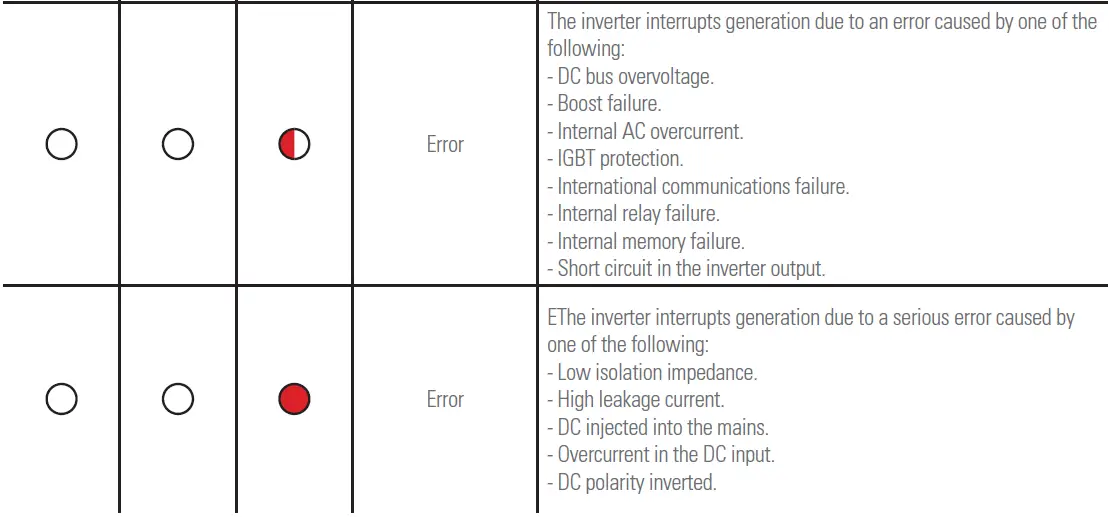
DISPLAY LED INDICATORS
The LEDs on the display will appear in one of three different states: on, off, or flashing.
The inverter uses different combinations of LEDs to indicate dif-ferent situations: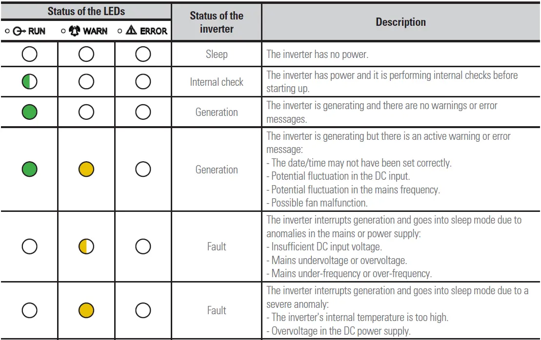
FAULT CODES
Fault codes are shown in the bottom right of the LCD screen. The table below details all of the fault codes that the inverter may display:
| Code | Fault | Description |
| A001 | PV UV | Solar panel input voltage low. |
| A002 | Bus UV | Inverter DC bus voltage low. |
| A003 | Grid UV | Mains voltage low. |
| A004 | Grid OV | Mains voltage high. |
| A005 | Grid UF | Mains frequency low. |
| A006 | Grid OF | Mains frequency high. |
| A007 | Clock Fail | Clock settings incorrect. |
| A009 | Cmd Shut | Forced external shut-off. |
| A011 | Grid Loss | Loss or disconnection from mains. |
| E001 | Input OV | Solar panel input voltage high. |
| E003 | Bus OV | Inverter DC bus voltage high. |
| E004 | Boost Fail | Voltage step-up malfunction. |
| E005 | Grid OC | Internal AC overcurrent. |
| E006 | OTP | The inverter’s internal temperature is too high. |
| E007 | Lo. Iso. R | Isolation impedance low. |
| E008 | IGBT drv | IGBT protection activated. |
| E009 | Int Comm | Internal slave-master communication error. |
| E010 | Ileak Fail | Leakage current high. |
| E011 | Relay Fault | Inverter output relay malfunction. |
| E012 | Fan Fail | Inverter internal fan malfunction. |
| E013 | Eeprom | Internal memory error. |
| E014 | DC inject | High level of DC injection at the AC output. |
| E015 | OutputShort | Short circuit in the output. |
| E018 | Input OC | Solar panel input current high. |
| E019 | Incnst | Inconsistent values for mains voltage, frequency, leakage current or DC injection on the AC side. |
| E020 | PowerReversed | Change in the polarity of the input terminals for the solar panels. |
| E025 | Locking | Device locked. |
SMARTPHONE APP
DOWNLOADING AND INSTALLING THE APP ON YOUR SMARTPHONE
Download the EQX-sun app from either the Play Store (Android) or App Store (iOS), depending on your smartphone’s operating system. After you have downloaded the app, follow the instructions it will give you.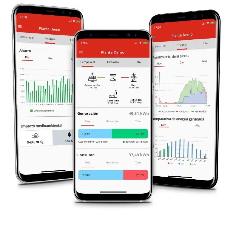
Avda. de la Serra 100 08460 Palautordera BARCELONA
Tel. +34 93 848 24 00 [email protected] SALICRU.COM
Information about our technical service and support network (T.S.S.), sales network and warranty is available on our website:
www.salicru.com


