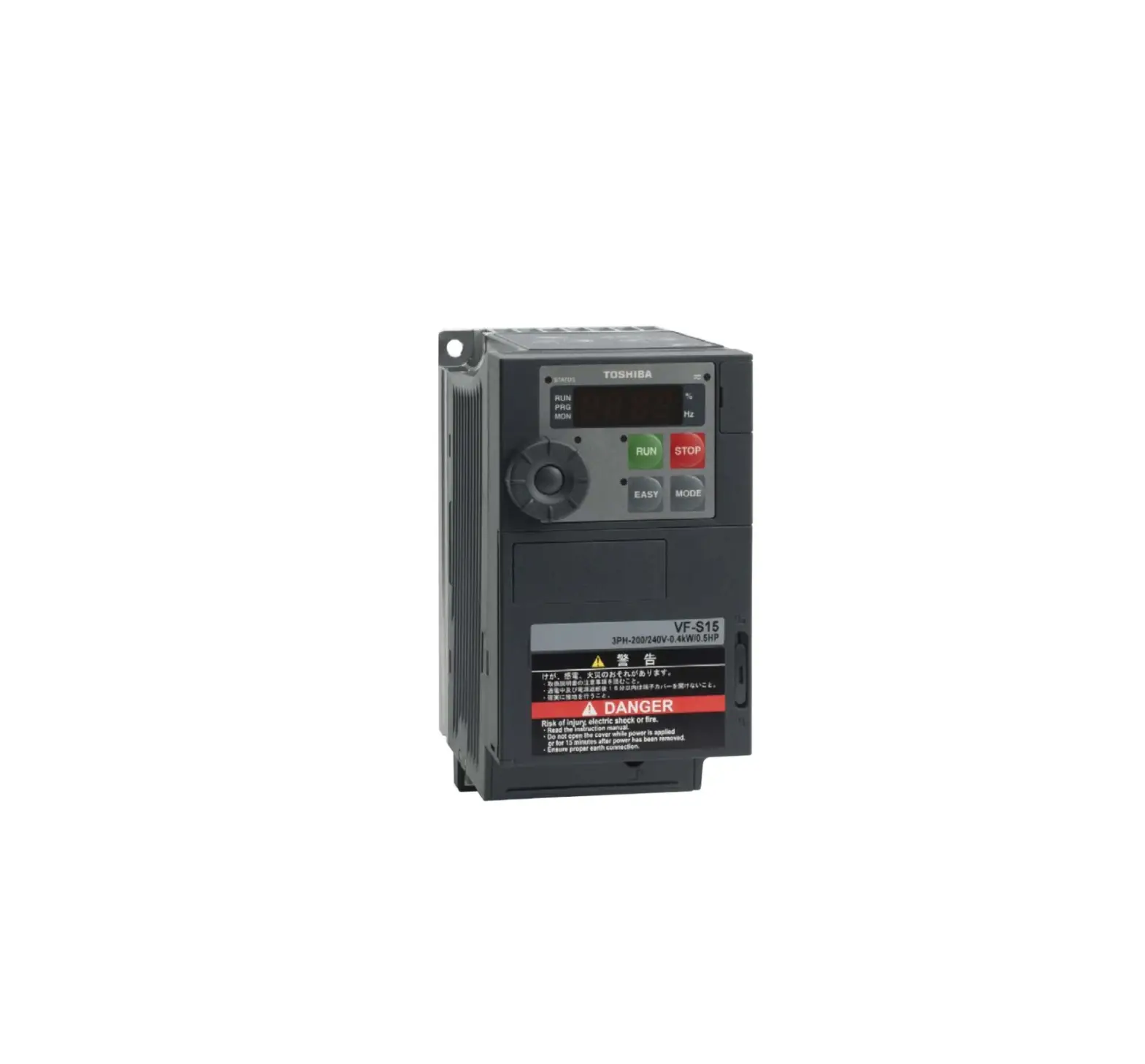
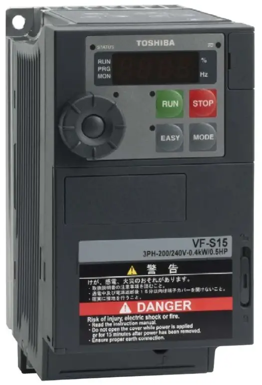
TOSHIBA VF-S15 Industrial Inverter
Safety precautions
The items described in these instructions and on the inverter itself are very important so that you can use safely the inverter, prevent injury to yourself and other people around you as well as to prevent damage to property in the area. Thoroughly familiarize yourself with the symbols and indications shown below and then continue to read the manual. Make sure that you observe all warnings given.
* Read the safety precautions of the instruction manual (CD-ROM) for information not mentioned here.
Explanation of markings
| Marking | Meaning of marking |
| Indicates that errors in operation may lead to death or serious injury. | |
| Indicates that errors in operation may lead to injury (*1) to people or that these errors may cause damage to physical property. (*2) |
- Such things as injury, burns or shock that will not require hospitalization or long periods of outpatient treatment.
- Physical property damage refers to wide-ranging damage to assets and materials.
Meanings of symbols
| Marking | Meaning of marking |
 | Indicates prohibition (Don’t do it). What is prohibited will be described in or near the symbol in either text or picture form. |
 | Indicates an instruction that must be followed. Detailed instructions are described in illustrations and text in or near the symbol. |
 | -Indicates warning. What is warned will be described in or near the symbol in either text or picture form. -Indicates caution. What the caution should be applied to will be described in or near the symbol in either text or picture form. |
- Limits in purpose
This inverter is used for controlling speeds of three-phase induction motors in general industrial use.
Single-phase input model is output by the inverter as three-phase output and cannot drive a single- phase motor.
![]() Safety precautions
Safety precautions
- This product is intended for general purpose uses in industrial application. It cannot be used applications where may cause big impact on public uses, such as power plant and railway, and equipment which endanger human life or injury, such as nuclear power control, aviation, space flight control, traffic, safety device, amusement, or medical. It may be considerable whether to apply, under the special condition or an application where strict quality control may not be required. Please contact your Toshiba distributor.
- Please use our product in applications where do not cause serious accidents or damages even if product is failure, or please use in environment where safety equipment is applicable or a backup circuit device is provided outside the system.
- Please do not use our product for any load other than three-phase induction motors in general industrial use. (Use in other than properly applied three-phase induction motors may cause an accident.) Single-phase input model is output by the inverter as three- phase output and cannot drive a single-phase motor.
| ■ Handling | |||
|
| ||
|
| ||
|
| ||
| ■ Handling | |||
|
| ||
|
| ||
| ■ Transportation & installation | |||
|
| ||
|
| ||
| ■ Transportation & installation | | ||
|
| ||
|
| ||
| ■ Wiring | | ||
|
| ||
|
| ||
|
| ||
| ■ Wiring | | ||
|
| ||
| Operations | | ||
|
| ||
|
| ||
| ■ Operations | |||
| |||
|
| ||
|
| ||
| ■ Maintenance and inspection | |||
|
|
| ||
|
| ||
| ■ Disposal | |||
|
(*). If you dispose of the inverter by yourself, this can result in explosion of capacitor or produce noxious gases, resulting in injury. | ||
Safety function
There are the following manuals at the back of the Japanese manual (Japanese model) in CD-ROM.
Refer to the manuals for safety function.
Safety function (STO) : E6581860 VF-S15 Safety function manual
ATEX : E6581861 VF-S15 ATEX Guide
Please operate the inverter in the following procedure 1 to 6.
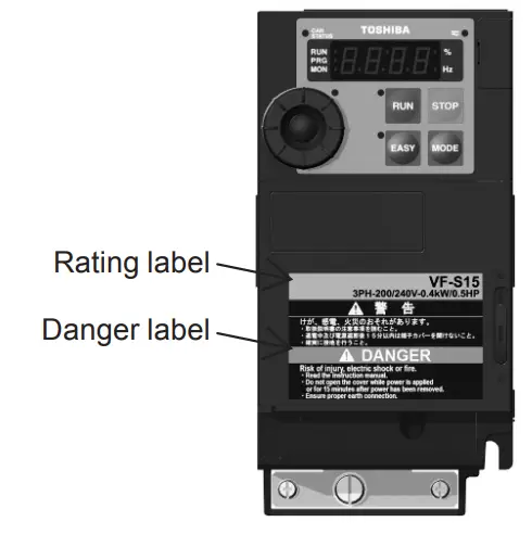
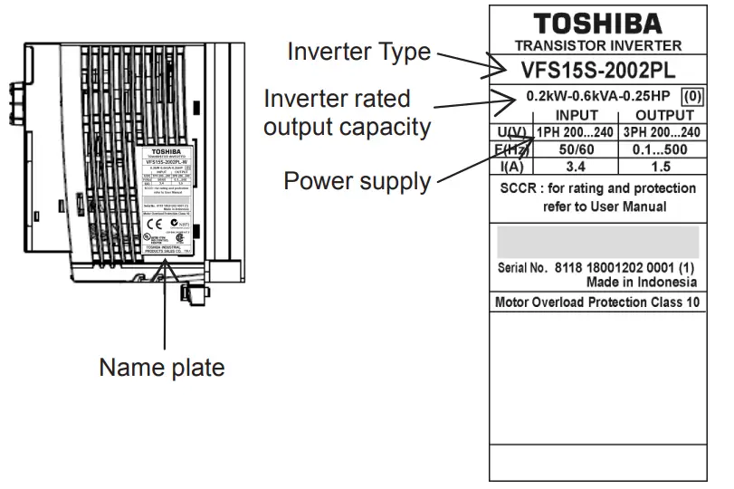
Check the purchase
Check that the inverter type is the same as your order.
Install the inverter
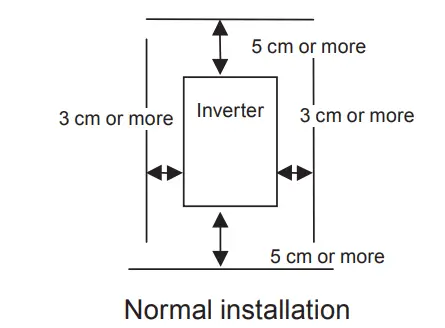
* For side-by-side installation, refer to the instruction manual.
Remove the terminal block cover

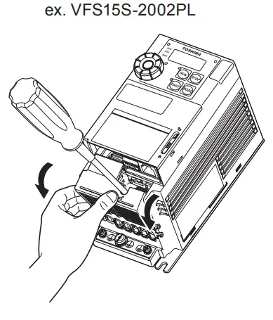
- Insert a screwdriver or other thin object into the hole indicated with the mark.
- While pressing on the screwdriver, rotate the
 terminal cover downward to remove it.
 - Next, remove the inside terminal block cover.
Connect to the power supply and the motor (wiring)
- Connect to the terminal R, S and T(single phase: R and S) of the power supply.

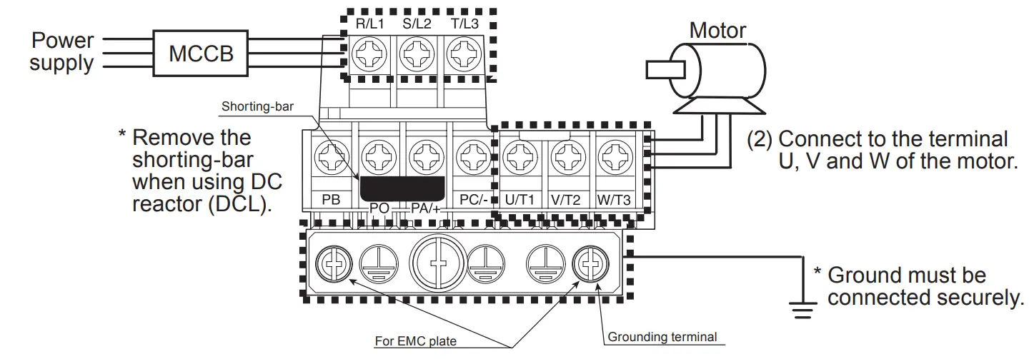
Power circuit terminal block
| Screw size | Tightening torque | |
| M3.5 screw | 1.0 N·m | 8.9 lb·in |
| M4 screw | 1.4 N·m | 12.4 lb·in |
| M5 screw | 2.4 N·m | 20.8 lb·in |
| M6 screw | 4.5 N·m | 40.0 lb·in |
| M4 screw (grounding terminal) | 1.4 N·m | 12.4 lb·in |
| M5 screw (grounding terminal) | 2.8 N·m | 24.8 lb·in |
| Voltage class | Applicable motor (kW) | Wire size (mm2) | |||
| Power circuit Note 1) | Grounding cable | ||||
| Input | Output | ||||
| without DCL | With DCL | ||||
| 3-phase 240V | 0.2-1.5 | 1.5 | 1.5 | 1.5 | 2.5 |
| 2.2 | 2.5 | 1.5 | 1.5 | 2.5 | |
| 4.0 | 4.0 | 2.5 | 2.5 | 4.0 | |
| 5.5 | 10 | 4.0 | 6.0 | 10 | |
| 7.5 | 16 | 6.0 | 10 | 16 | |
| 11 | 25 | 10 | 16 | 16 | |
| 15 | 35 | 16 | 25 | 16 | |
| 1-phase 240V | 0.2-0.75 | 1.5 | 1.5 | 1.5 | 2.5 |
| 1.5 | 2.5 | 2.5 | 1.5 | 2.5 | |
| 2.2 | 4.0 | 4.0 | 1.5 | 4.0 | |
| 3-phase 500V | 0.4-2.2 | 1.5 | 1.5 | 1.5 | 2.5 |
| 4.0 | 2.5 | 1.5 | 1.5 | 2.5 | |
| 5.5 | 4.0 | 1.5 | 2.5 | 4.0 | |
| 7.5 | 6.0 | 2.5 | 2.5 | 6.0 | |
| 11 | 10 | 4.0 | 6.0 | 10 | |
| 15 | 16 | 6.0 | 10 | 16 | |
Turn on the power supply
Set the setup menu after power on.
![]() Caution If incorrect setting, the drive may have some damage or unexpected movement. Be sure to set the setup menu correctly.
Caution If incorrect setting, the drive may have some damage or unexpected movement. Be sure to set the setup menu correctly.
| Setting dial | LED display | Operation |
 | Power on | |
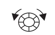 | 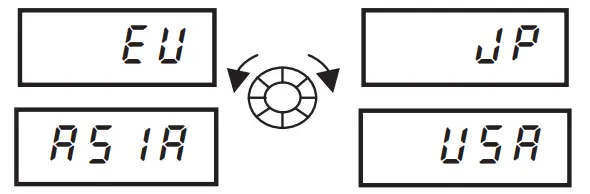 | Turn the setting dial and select region. |
 |  | Press the setting dial |
 | Finish setup |
| Parameter setting | ||||
| Main region | Europe | Asia, Oceania | North America | Japan |
| Motor
| 230/400(V) | 230/400(V) | 230/460(V) | 200/400(V) |
| 50(Hz) | 50(Hz) | 60(Hz) | 60(Hz) |

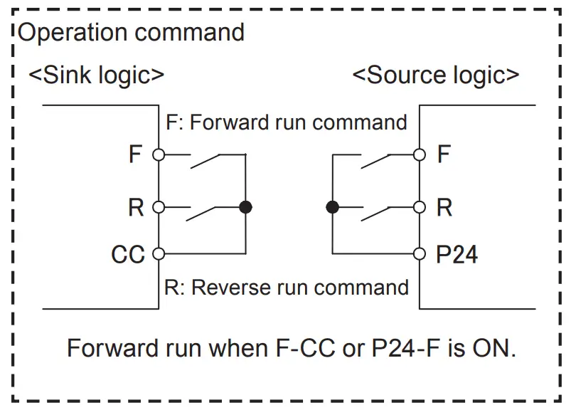
Note) When you operate the inverter with external signals, please select Sink logic, Source logic, or PLC(external power supply) by SW1.
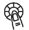
Operate the inverter
Panel operation is possible with default settings.
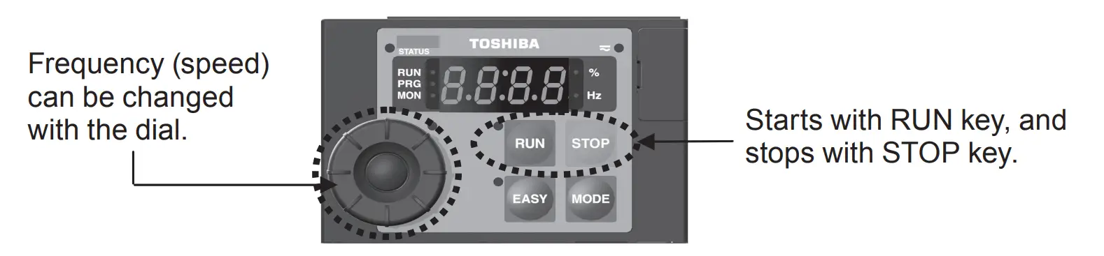
Operate the inverter with external signals
Wire the control circuit, set the parameter and select SW1.
Wiring
| Screw size | Recommended tightening torque |
| M3 screw | 0.5 N·m |
| 4.4 lb·in |
Stripping length: 6 (mm) Screwdriver:
Small-sized flat-blade type
(Blade thickness: 0.5 mm, blade width: 3.5 mm)
| Conductor | 1 wire | 2 wires of same size |
| Solid | 0.3-1.5mm2 (AWG 22-16) | 0.3-0.75mm2 (AWG 22-18) |
| Stranded |
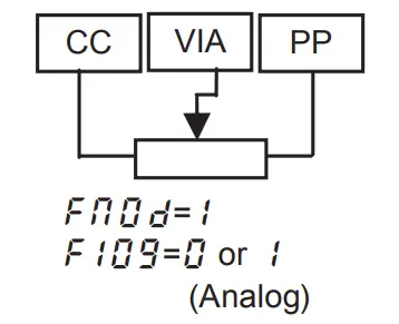
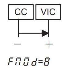
Frequency setting
- Potentiometer

- Current input (4 to 20mA)

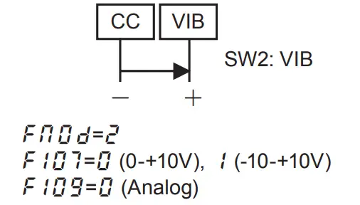
- Voltage input (0 to 10V) or (-10 to +10V)

Parameter setting
Determine the operation method with ![]() and frequency setting with
and frequency setting with ![]()
| Title | Function | Adjustment range | Default setting |
| Command mode selection | 0: Terminal block, 1: Panel 2: RS485, 3: CAN open, 4: Option | 1 | |
| Frequency setting mode selection 1 | 0: Setting dial 1, 1: Terminal VIA 2: Terminal VIB, 3: Setting dial 2 4: RS485, 5: UP/DOWN from logic input 6: CAN open, 7: Communication option 8: Terminal VIC 11: Pulse train input, 14: sro | 0 |
Select the signal of terminal VIA and VIB
| Analog input terminal selection (VIB) | 0: 0-+10V, 1: -10-+10V | 0 | |
| Analog/logic input selection (VIA/VIB) | 0 to 4 *See the instruction manual for detail. | 0 |
Main parameters
| Contents | Title | Function | Adjustment range | Default setting |
| Set acceleration/ deceleration time to suit the machinery. The acc/dec value is time that output frequency reach from 0Hz to fh value. |  | Acceleration time 1 | 0.0-3600 (360.0) (s) | 10.0 |
 | Deceleration time 1 | 0.0-3600 (360.0) (s) | 10.0 | |
 | Maximum frequency | 30.0-500.0 (Hz) | 80.0 | |
| Set the upper and lower limit of the output frequency | Upper limit frequency | 0.5-fh (Hz) | *1 | |
 | Lower limit frequency | 0.0-ul (Hz) | 0.0 | |
| Select the V/f control mode to suit the machine |  | V/F control mode selection | 0: V/F constant 1: Variable torque 2: Automatic torque boost control 3: Vector control 4: Energy-saving 5: Dynamic energy- saving 6: PM motor control 7: V/F 5-point setting | *1 |
| Adjust the electronic thermal for the motor protection. | Motor electronic-thermal protection level 1 | 10-100 (%/(A)) | 100 |
*1: Default setting values vary depending on the setup menu setting.
Panel operation
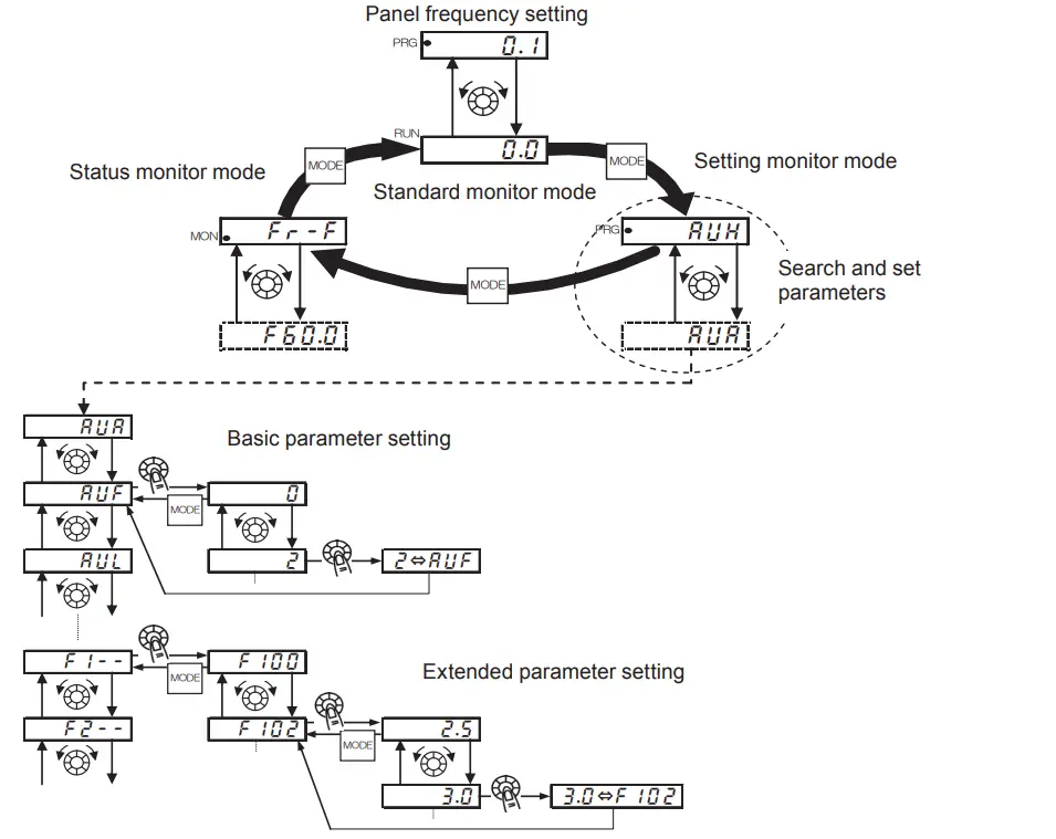
Setting parameters
- Select the parameter. (Turn the setting dial.)
- Read the setting value. (Press the center of the setting dial.)
- Change the setting value. (Turn the setting dial.)
- Determine the setting value. (Press the center of the setting dial.)
TOSHIBA INDUSTRIAL PRODUCTS AND SYSTEMS CORPORATION
Mo1or Drive Division
580, Horikawa-cho, Saiwai-‘Ku, Kawasaki, Kanagawa
212-0013 Japan
TEL : +81-44-520-0828
FAX : +81-44-520-0508
https://www.toshiba-tips.co.jp/en/oontact/eu.html
TOSHIBA INTERNATIONAL CORPORATION
13131 West Little York RD., Houston
TX 77041, U.S.A
TEL: +1 -713-466-0277
FAX:+ 1-713-466-8773
TOSHIBA AMERICADO SUL LTDA.
Avenida lbirapuera, 2332, Torte I,
5° floor City of Sao Paulo Brasil
TE: L: +55-11-4083-7900
FAX : +55-11-4083-7910
TOSHIBA INDUSTRIAL PRODUCTS AND’
SYSTEMS SHANGHAI CORPORATION
Room No.906, Raffles City (Offfce Tower) , No. 268,
Xizang Middle Road, Huangpu District, Shanghai,
P.R.China
TEL: +86-21-6361-3300
FAX: +86-21-6373-1760
TOSHIBA ELECTRONIC COIVIPON’
ENTS TAIWAN CORPORATION
12F, No.8, Min Sheng E. Rd. Sec. 3, Taipei 10480, Talwan
TEL: +886-2-2508 9988
FAX: +886-2-2508 9997
TOSHIBA ASIA PACIFIC PTE LTD
20 Pasir Panjang Road #13-27/28,.
Mapletree Business City, Singapore 117439
TEL: +65-6297 ~0990
FAX: +66-6305-5561
TOSHIBA INTERNATIONAL CO.ff PORATION PTY. LTD.
11 A Gibbon Road, Winston Hills, Sydney, NSW 2153,
Australia
TEL: +61-2-8867-6200
FAX: +61-2-9624-7104
TOSHIBA IN;OIA PRIVATE LIMITED
3RD Floor, Building No.10, Tower 8 1 Phase-I 1,
DLF Cyber City, Gurgaon-12202, India
TEL: +91-124-4996,600
FAX: +91 -124-4996665
TOSHIBA G,ULF FZE
P.O.Box 61028, Jelbel Ali, Free Zone, Dubai, U.A.E
TEL: +971 -4-8817789
FAX: +971 -4-8818985
TOSHIBA RUS LLC
Klevskaya st, 7, entrance 7, floor 12,, Moscow,
121059, Russian Federation
TEL: +7-495-642-8929
FAX : + 7-495-642-8908
TOSHIBA AFRICA (PTY) LTD – SOUTH AFRICA
10th Floor, Sandton Office l”owers, 5th Street,
Sandton, 2196, South Africa
TEL : +27-11-305-2820
FAX :+27-11-326-6074
For further information, please contact to nearest Toshiba Representative or Motor Drive Division, Global Sales Department – Producer Goods. The data in this manual are subject to change without any notice.