Nilfisk BF16 Multi Booster
Description
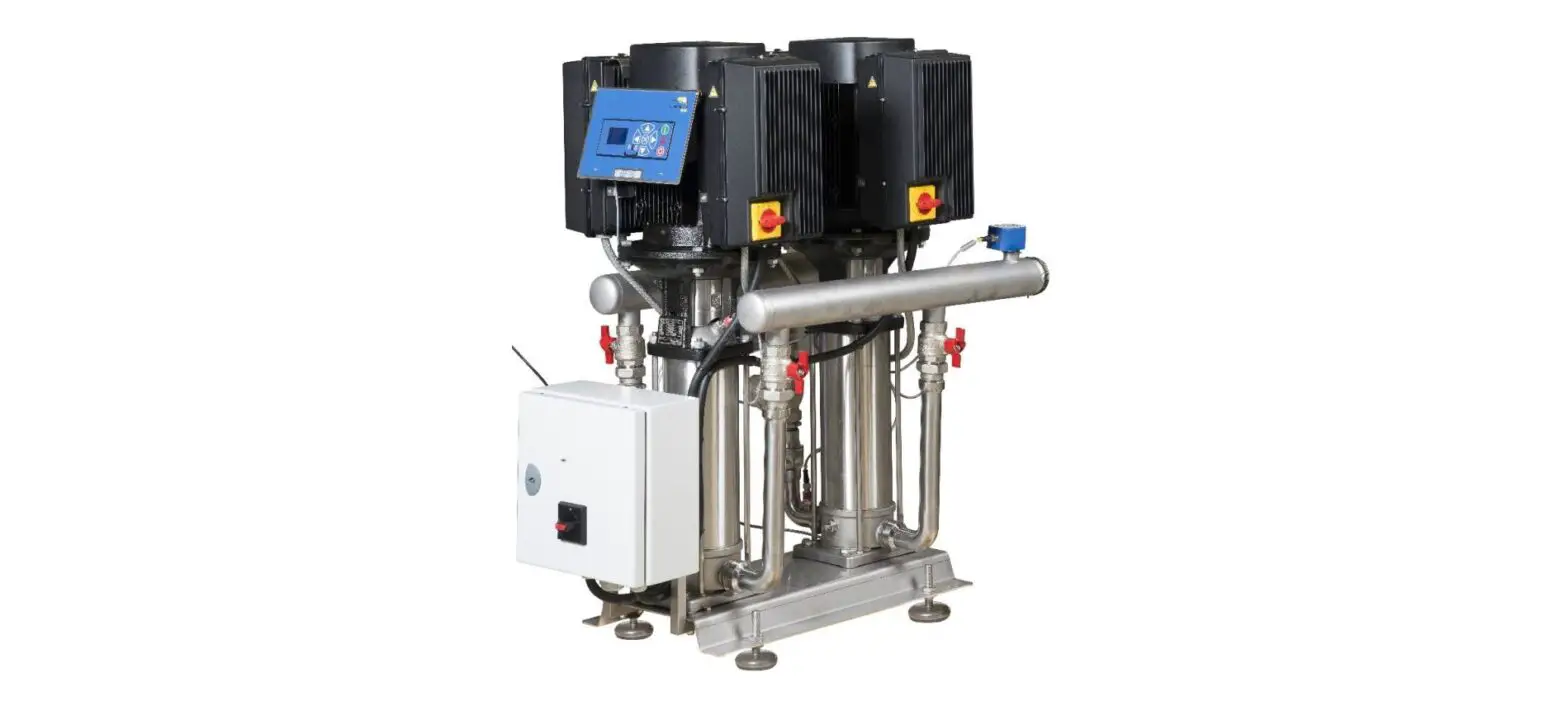
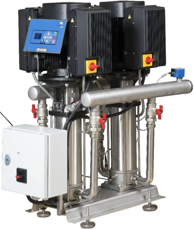
The Booster in the Chameleon Plus range is a completely functioning pumping station that supplies pressurized water to connected satellite hygiene stations. Therefore the Booster must be supplied with water in sufficient quantity and power according to specifications. The station is then ready for hygiene duties.
The Booster is fitted with a frequency-controlled pump which ensures a constant working pressure independent of usage pattern.
Important: Do not use the wa-ter from the system for applications other than cleaning.
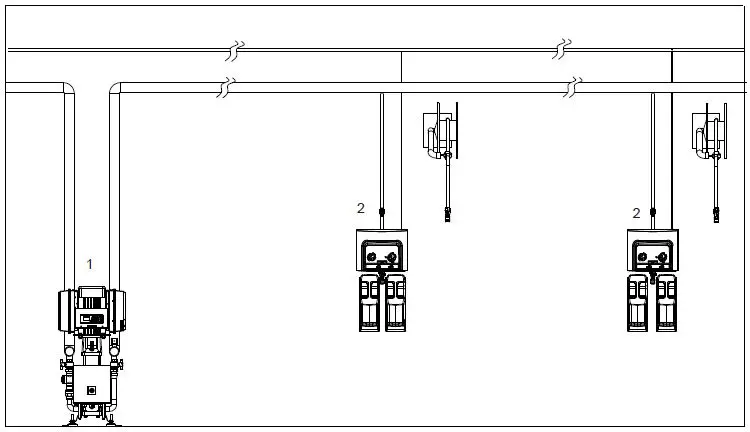
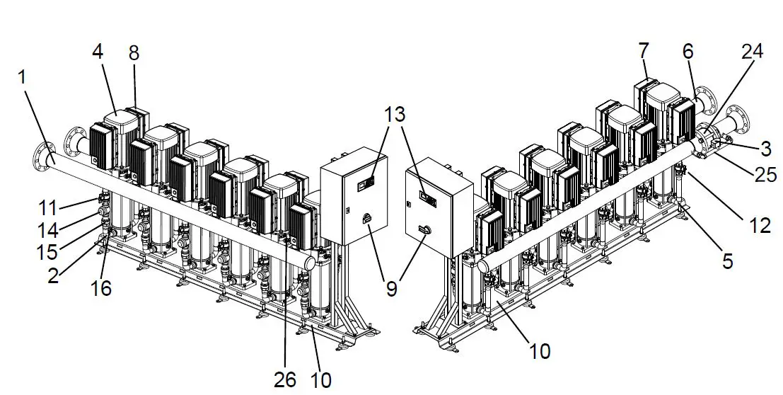
A typical Floor Booster installation is shown in fig. 2
- Booster (1)
- Satellite (2)


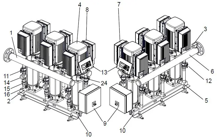
1.7 Multi Booster BF16 – BF24
- Water inlet
- Manifold inlet
- Trigger sensor, flow sensor
- Pump
- Manifold outlet
- Outlet pipe
- Inverter box
- Filter box
- Electrical connection box
- Floor bracket
- Inlet ball valve
- Outlet ball valve
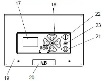
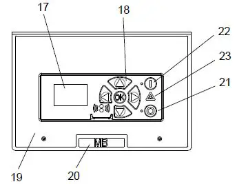
- Operation panel
- Strainer
- Non-Return Valve
- Pressure sensor
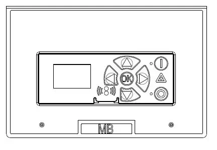
- Display
- Navigation buttons
- Label
- Name Label
- • O Pushbutton.Stop
- • I Pushbutton. Start
- • Δ Lamp. Alight by error
- Pressure sensor
Advanced Booster BF32 – BF40 – BF48
- Water inlet
- Manifold inlet
- Trigger sensor, flow sensor
- Pump
- Manifold outlet
- Outlet pipe
- Inverter box
- Filter box
- Electrical connection box
- Floor bracket
- Inlet ball valve
- Outlet ball valve
- Operation panel
- Strainer
- Non Return Valve
- Pressure sensor
- Display
- Navigation buttoms
- Label
- Name Label
- • O Pushbutton.Stop
- • I Pushbutton. Start
- • Δ Lamp. Alight by error
- Nonreturn valve for by-pass
- By-pass
- Pressure sensor
Operating Diagrams acc. ISO14617
Multi Booster BF16 – BF24 – BF32 – BF40 – BF48
- B. Ball valve.
- F. Filter
- FST. Flow switch.
- C. Check valve.
- PE. Pressure sensor.
- TE. Temperature sensor.
- CP. Centrifugal pump.
- D. Outlet.
- PU. Pump unit.
- W. Water inlet.
- SN : Socket no
Maintenance
The Booster unit is maintenance-free. However, we recommend cleaning the booster unit in connection with the occasional cleaning of the other equipment in the area. The filter must be cleaned at convenient intervals (approx. every 1-3 months) depending of the number of impurities in the water. 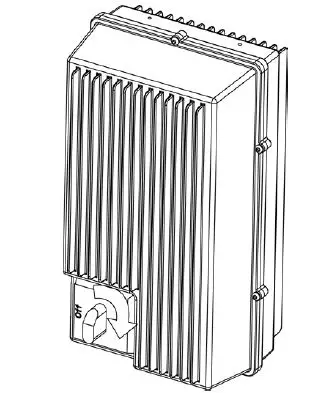
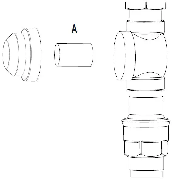
Filter
- Press “0” on the control panel to stop the Booster.
- Interrupt the master switch (Fig. 1).
- Close the water inlet .
- Open a tap to release the system of pressure.
- Remove the filter (A, Fig. 2) and place it in a descaling solution.
 Note: MB systems are not delivered with a factory-mounted filter. In case a filter is mounted in a MB system, the descaling procedure is exactly the same until the scale is dissolved.
 - Rinse the cleaned filter thoroughly and remount.
- Min filter mesh size 800μ -> 1500μ.
 Note: MB systems are not delivered with a factory-mounted filter. In case a filter is mounted in a MB system, the descaling procedure is exactly the same until the scale is dissolved.
Before a longer production stop
If long production stops are planned (more than 6 months) and the pump is drained, it is recommended that the pump is secured as follows:
- Remove the coupling safety guard.
- Spray a couple of drops of silicone oil onto the axle between the top section and the coupling. Carefully follow the instructions given in the manual provided by the pump supplier.
Start
New system
In order to ensure a problem-free start up of a new system the pipe system must be flushed and bled.
Bleeding the pipe system
- Turn on the water supply to rinse and bleed the entire system. If satellites are installed open the tap furthest away until no air or dirt comes out. Then rinse and bleed the next tap and continue until the tap closest to you has been rinsed and bled.
- Mount satellites, if any
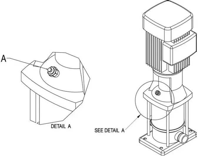
Bleeding the pump - Press “0” on the control panel to stop the Booster.
- Loosen the relief plug (A, Fig34) 1-2 revolutions until water and air begin to flow out.
Note. Never loosen the relief plug while the pump is running as this may damage the packing and cause personal injury. - Tighten the relief plug again
- Start the pump so that all remaining air pockets are forced up to the top of the pump


- Stop the pump.
- Loosen the relief plug 1-2 revolutions again and bleed the system until only water flows out.
- Tighten the relief plug once more. The Booster is now ready for operation. Press “I” on the control panel. (see fig. 4).
Daily Operation
Start
- Check that water supplies for the system are open.
- Press “I” on the control board in order to start up the unit.
Stop
- Press “0” on the control panel to stop.
- Turn off the water supply.
- Switch off the air supply.
Note. Due to the following it is very important always to switch off both water and air supply after use:
- If the air supply is open when the main station or satellites are not in use, air might leak into the water line. If this happens, the system must be bled once more.
- The water separator, which is a part of the air regulator, is only to be emptied when the air supply is closed. After a long time production stop (holidays etc) it might be necessary to bleed the piping system and the booster unit again
Service
Service may only be carried out by authorized and qualified personnel.
Warning: The system must only be serviced when there is no voltage or pressure on the system.
- Turn off the main switch at the control box (Fig. 1)
- Open a water outlet to depressurize the system.
Components
Pump/motor
Pump/motor are maintenance-free, see section 2.2
Control system
Maintenance-free
If defective: Call service technician
Flow trigger
Maintenance-free.
If defective, replace the flow switch. The orientation of the flow switch has to be done in such way that the plug/cable end of the switch is pointing opposite the flow direction 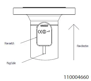
Adjustment of flow switch
When the flow switch is replaced/installed it has to be adjusted.
- Press “1” on the control panel to turn on the machine.
- Turn the “rinse/foam” handle on a satellite to foam position.
- Activate the spray handle on the outlet hose of the satellite so water runs out.
- Check that the flow switch is turned the correct way (the wire must be opposite the flow direction) (see picture).
- Remove the white plug/screw before adjusting (see picture).
- Adjust the flow to one green diode lights up (see picture).
- Close the spray handle again and check that the red diode lights up.
- Remount the white plug/screw.
The flow switch is now adjusted. 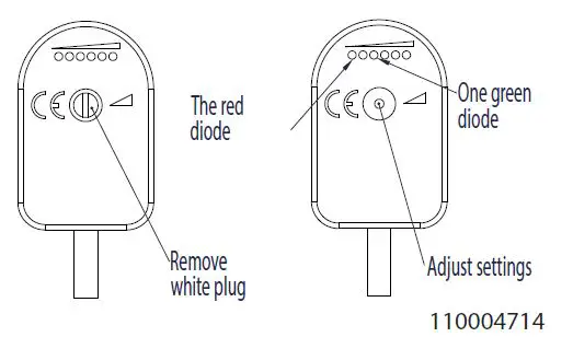
Non-return valve / inlet side
Maintenance – free.
If defective, replace the non-return valve.
Recycling and scrapping
Recycle the wrapping and scrap the machine according to recommendations from the local authorities
Troubleshooting
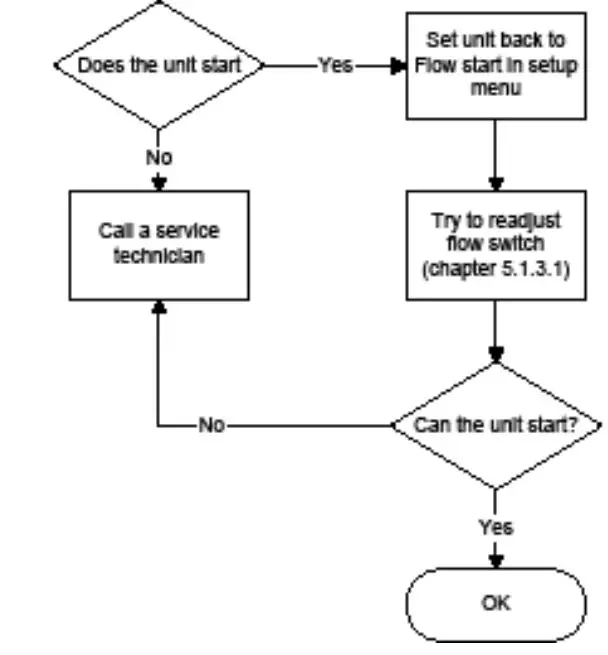
The unit does not start 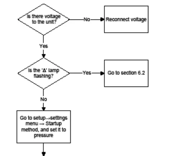
The “Δ”- lamp on the control panel is on 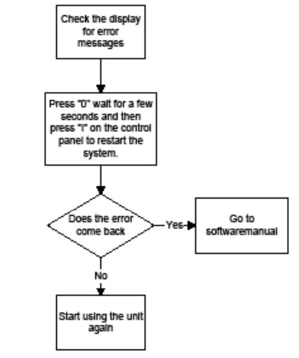
If the inlet pressure is low or unstable 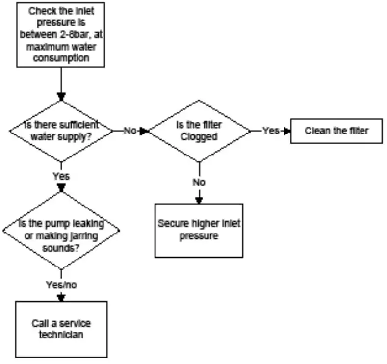
Recommended spare parts
The recommended spare parts are marked with * in the spare part manual
Specifications
| Technical Data | Multi Booster. | |||||
| BF16 | BF24 | BF32 | BF40 | BF48 | ||
| Max. Outlet pressure. | bar | 25* | 25* | 25* | 25* | 25* |
| Consumption during rinsing. | L/min | 440 | 660 | 880 | 1100 | 1320 |
| Consumption during foaming. | L/min | 160 | 240 | 320 | 400 | 480 |
| Min. supply pressure. | bar | 2 | 2 | 2 | 2 | 2 |
| Max. supply pressure. | bar | 8 | 8 | 8 | 8 | 8 |
| Min. water supply. | L/min | 500 | 750 | 1000 | 1250 | 1500 |
| Max. water temp. | °C | 70 | 70 | 70 | 70 | 70 |
| Pipe dimension inlet Ø | inch | 2 1/2″ | 3″ | 4″ | 4″ | 4″ |
| Pipe dimension outlet Ø | inch | 2 1/2″ | 3″ | 4″ | 4″ | 4″ |
| Electricity | ||||||
| Supply voltage | V | 3/PE 400 V ±10% | ||||
| Frequency | Hz | 50±2 | ||||
| Motor load (kW) | kW | 22 | 33 | 44 | 55 | 66 |
| Installation to EN 60204-1 | ||||||
| Nominal current | A | 55 | 82,5 | 110 | 137,5 | 165 |
| Fuse | A | 63 | 100 | 125 | 160 | 200 |
| L1, L2, L3, PE | mm2 | 2.5 | 2.5 | 2,5 | 6 | 6 |
| General | ||||||
| Sound level ISO 11202 | dB | 85 dB | – | – | – | – |
| Dimensions | mm | 1112x530x1043 | 1112x530x1477 | 1268x665x2399 | 1268 x 665 x 2822 | 1268 x 665 x 3248 |
| Weight (kg) ca | kg | 190 | 300 | 400 | 500 | 600 |
Note: Pump pressure 20 bar + inlet pressure max. 25 bar
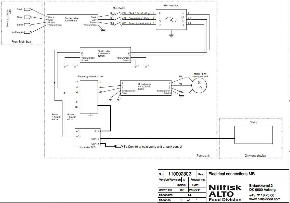
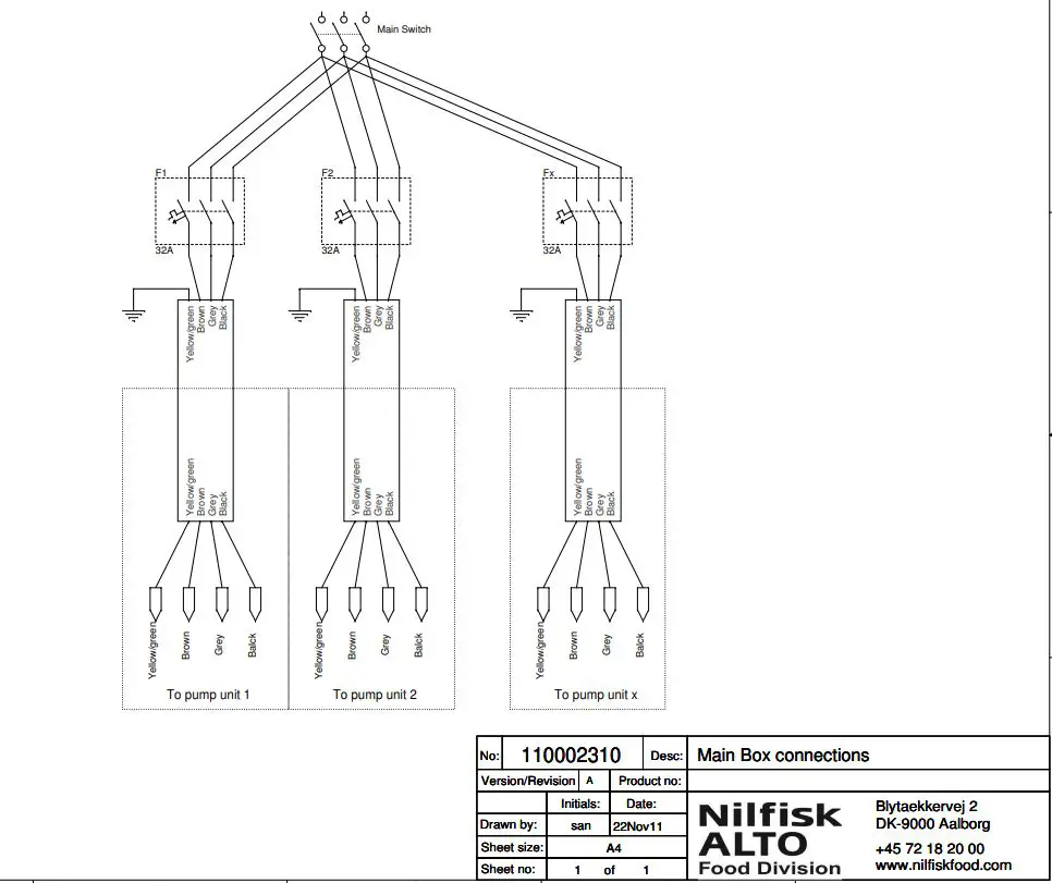
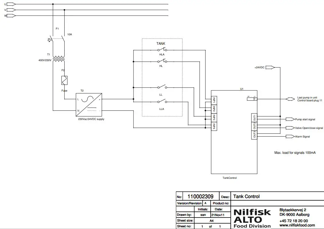
Electric diagram 
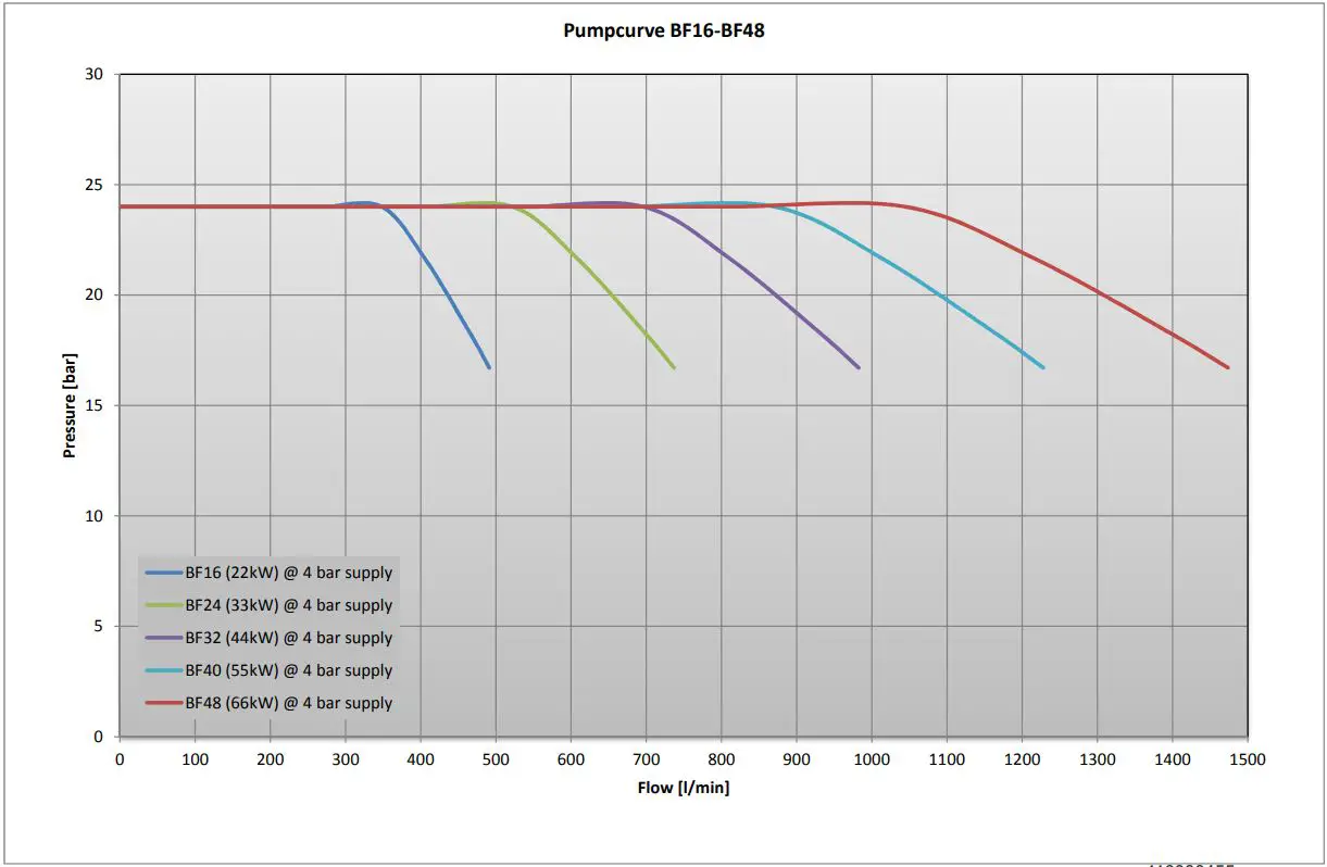
Pump curve 
Declaration of Conformity
We Nilfisk FOOD, declare under our sole responsibility that the products BF16+, BF24+, BF32+, BF40+, BF48+, to which this declaration relates, are in conformity with these Council directives on the approximation of the laws of the EC member states:
Function: Pumping Station
Model/Type: BF16-2+, BF24-3+, BF32-4+, BF40-5+, BF48-6+.
Serial number: All
Machinery Directive (2006/42/EC:2006-05-17).
Standard used: EN 60335-2-41/A2:2010
EMC Directive (2004/108/EC:2004-12-15).
Standard used: EN 55014-1/A1:2009 and EN 55014-2/A2:2008
Standard used: EN 61000-3-2/A2:2009 and EN 61000-3-3:2008


