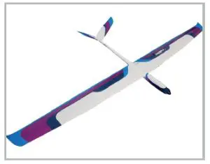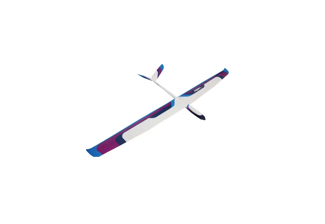
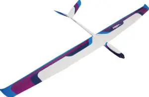
robbe SAPPHIRE! Instruction Manual

SAFETY INSTRUCTIONS FOR CONTROLLERS
- Observe the technical data of the controller.
- Observe the polarity of all connection cables.
- Avoid short circuits at all costs.
- Install or package the regulator so that it cannot come into contact with grease, oil or water.
- Effective interference suppression measures on the electric motor with, for example, interference suppression capacitors
- Ensure adequate air circulation.
- Never reach into the turning circle of the propeller during start-up Risk of injury
Dealing with model aircraft and vehicles requires technical understanding and a high level of safety awareness. Incorrect assembly, incorrect adjustment, improper use or the like can lead to personal injury or damage to pro- perty. Sudden starting of connected motors can lead to injuries due to rotating parts such as propellers. Always stay away from these rotating parts when the power source is connected. All drive components should be safely and securely mounted during a function test. Use is only permitted within the scope of the technical specifica- tion and only for RC hobby applications. Before use, check that the speed controller is compatible with your drive motor or power source. Never operate the speed controller (correct speed controller) with external power supply units. Speed controllers should always be protected from dust, moisture, vibration and other mechanical stresses. Even splash-proof or waterproof equipment should not be permanently exposed to moisture or moisture. High operating temperatures or poor cooling should be avoided. The recommended temperature range should be approximately between -5°C and +50°C. Ensure proper connection and do not cause reverse polarity which
would permanently damage the speed controller. Never disconnect the device from the motor or battery during operation. Use high-quality plug systems with sufficient load capacity. Avoid strong bending or tensile stress on the connecting cables. After termination of flight or driving operation, disconnect the battery to prevent deep discharge of the battery. This would cause permanent damage. For the BEC version of the controller, check that the BEC power of the device is sufficient for the servos used. Speed controllers should be installed as far away as possible from other remote control components. We recommend carrying out a range test before operation. We recommend regular checking of the controller for function and externally visible damage. Do not continue ope- rating the controller if you notice any damage. The connection cables must not be extended. This can lead to unwanted malfunctions. Despite existing safety and protective devices of the device, damage may occur which is not covered by warranty. The warranty also expires if changes are made to the device.
Important information:
The receiver system is powered by the built-in BEC system of the controller.
For commissioning, always move the throttle stick to the „Motor off“ position and switch on the transmitter. Only then connect the battery. To switch off always disconnect the connection battery motor controller, first then turn off the transmitter. During the functional test, move the servos of the rudders to neutral position with the remote control (stick and trimming lever on the transmitter to the middle position). Please make sure to leave the throttle stick in the lowest position so that the engine does not start. For all work on to the parts of the remote control, motor or controller, follow the instructions supplied with the units. Also read the instructions of the battery and the charger carefully before commissioning. Check the engine mounting bolts in the fuselage regularly for tightness.
SAFETY INSTRUCTIONS FOR RECHARGEABLE BATTERIES
- Do not immerse the battery in water or other liquids.
- Do not heat, throw into fire or microwave.
- Do not short-circuit or charge with reversed polarity
- Do not expose, deform or throw the battery
- Do not solder directly on the battery
- Do not change or open the battery
- Only charge the battery with suitable chargers, never connect it directly to a power supply unit.
- Never charge or discharge the battery or charger on a flammable surface.
- Never leave the battery unattended during charging or discharging processes.
- Never charge or discharge the battery in direct sunlight or near heaters or fire.
- Do not use the battery in places subject to high static discharge.
All this can cause the battery to be damaged, explode or even catch fire!
- Keep the battery away from children
- Keep leaked electrolyte away from fire, as it is highly flammable and may ignite.
- The electrolyte liquid should not get into the eyes, if it does, rinse immediately with plenty of clear water and then see a doctor.
- The electrolyte liquid can also escape from clothes and other objects with a lot of water or washed off.
- Observe the safety instructions of the battery manufacturer and the charger manufacturer
WARRANTY
Our articles are equipped with the legally required 24 months warranty. Should you wish to assert a justified war- ranty claim, always contact your dealer, who is responsible for the warranty and the processing. During this time, any functional defects that may occur, as well as manufacturing or other problems, will be rectified.
Material defects corrected by us free of charge. Further claims, e.g. for consequential damages, are excluded. The transport to us must be free, the return transport to you is also free. Freight collect shipments cannot be accepted. We cannot accept liability for transport damage and loss of your consignment. We recommend appropriate insurance.
To process your warranty claims, the following requirements must be met:
- Attach the proof of purchase (receipt) to your shipment.
- The units have been operated in accordance with the operating instructions.
- Only recommended power sources and original robbe accessories have been used.
- There is no moisture damage, external interference, reverse polarity, overloading or mechanical damage.
- Attach relevant information for finding the fault or defect.
DISCLAIMER
Robbe Modellsport cannot monitor compliance with the assembly and operating instructions or the conditions and methods for installation, operation, use and maintenance of the model components.Therefore, we accept no liability for losses, damage or costs arising from or in any way connected with incorrect use and operation.To the extent permitted by law, the obligation to pay damages, irrespective of the legal grounds, shall be limited directly to the invoice value of the claims arising from the event causing the damage.
INSURANCE
Ground-based models are usually covered by personal liability insurance. Additional insurance or extension is required for aircraft models. Check your insurance policy (private liability) and take out suitable insurance if necessary.
CONFORMITY
 Robbe Modellsport hereby declares that this device complies with the essential requirements and other relevant regulations of the corresponding CE directives. The original declaration of conformity can be found on the Internet at www.robbe.com, in the detailed product view of the respective device description or on request. This product can be operated in all EU countries.
DISPOSAL
 This symbol means that small electrical and electronic devices must be disposed of at the end of their useful life, separated from the household refuse. Dispose of the device at your local municipal collection point or recycling centre. This applies to all countries of the Euro- pean Union and other European countries with a separate collection system.
TECHNISCHE DATEN TECHNICAL DATA INFORMATIONS TECHNIQUES
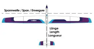
| Spannweite Span Envergure | 2900 mm |
| Länge Length Longueur | 1290 mm |
| Gewicht (leer) ca. Weight (dry) approx. Poids (vide) env. | |
| Gewicht (flug) ca. Flying weight approx. Poids (en vol) env. | 2480 g |
| Tragflächeninhalt Wing Area Surface des ailes | 69,1 dm² |
| Profil Airfoil Profil | HQ 2,5/9 |
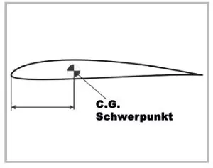
| Schwerpunkt C.G. Centre de gravité | 83 – 88 mm hinter Nasenleiste behind the leading edge derrière le bord d‘attaque |
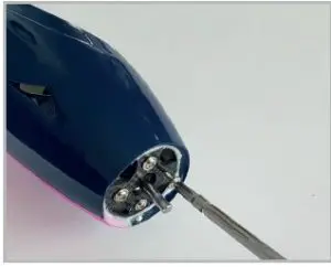
cables pointing down. Use thread locker.
- Screw the motor behind the motor bulkhead with the cables pointing down. Use threadlocker.

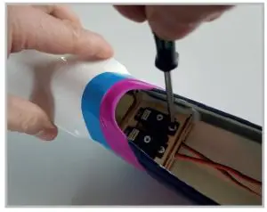
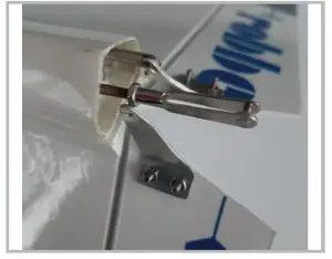
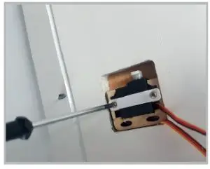
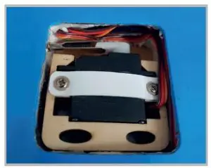
- Now screw both V-tail servos into the servo board in the fuselage.

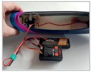
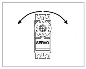
- Set the two servos to their neutral position using a servo tester.
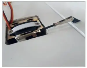
- Hang the Z-bend in the third hole of the servo arm. Mount both servo arms at a 90° angle and screw them tight.

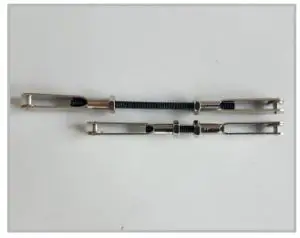
- At the end of the Bowden cables, screw on the two M2 nuts and clevises. The more precise length adjustment will follow later.

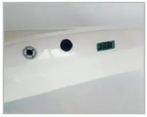
- We recommend the Multilock system for wing locking. Install this according to the enclosed instructions. Alternatively, the wing can simply be secured with a strip of tape.

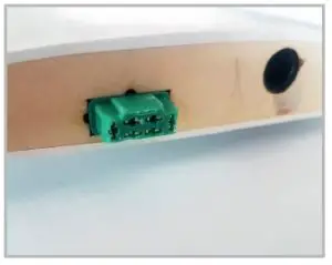
- We recommend making the electrical connection using MPX plugs. This will save you cable clutter later when setting up at the airfield.
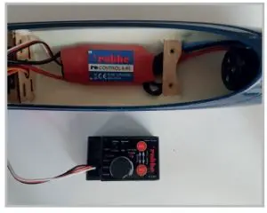
- Connect the controller to the cables of the motor. Let the cables run underneath the mounting bar.

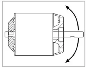
- Check now already the running direction of the motor clockwise (in flight direction) and exchange two of the three connecting cables if necessary.
- Only then is the battery board attached. Pull the regulator plug and the battery strap through the recesses and screw the board hand-tight.
- Then attach the propeller to the motor shaft by carefully tightening the nut. Now the spinner cap can be mounted.


 Caution: Make sure that all rotating components are properly and firmly seated! Faulty installation can represent a safety risk and cause personal and property damage!
V-LEITWERK / V-TAIL / DÉRIVE EN V
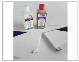
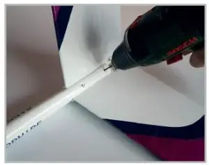
- Glue both tail halves with epoxy resin.
- Fix both tail halves on the underside exactly aligned with tape as hinge help.
- Coat both end faces with epoxy resin.
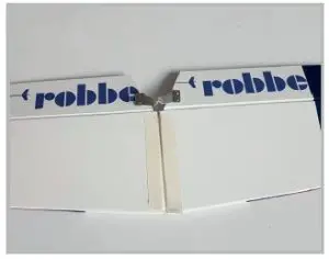
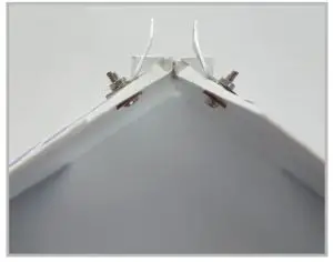
- Place the 110° template between the two halves and fold up the tail halves. Now fix the tail unit with a long piece of tape so that the angle is maintained.
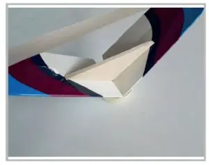
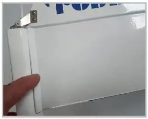
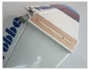
- After the glue has cured, remove the template and tape. Now insert the tailplane into the fuselage recess and adjust the support wedges.
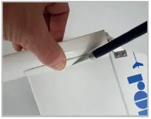
- Mark exactly where the wedges end and remove the tailplane covering film underneath to allow for secure and stable bonding.

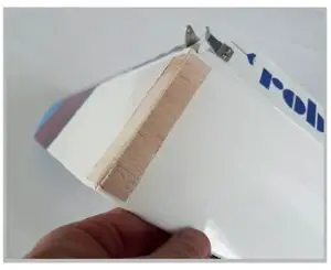
- Now glue the wedges to the tailplane in the fitted condition. Do not glue to the fuselage!
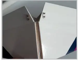
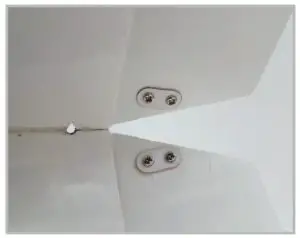
- After curing, the 3mm holes can be transferred to the tailplane. Make sure that the tail unit is completely seated correctly in the fuselage.
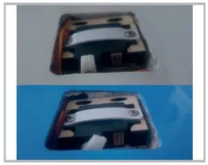
- Screw the control horns to the bottom of the control surfaces. The distance between the linkage points should be approx. 13mm.
- The distance to the axis of rotation should be approx. 6mm.
- Finished plug-in tail unit.
- The tail unit can now be bolted into the fuselage and the clevises adjusted. At 90° servo arm the control surfaces should be neutral.

TRAGFLÄCHE / WING / AILES
- Pull the servo extension cables into the cable bays.
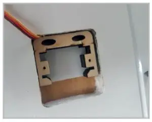
- Glue the servo frames flush with the sides of the servo bays using epoxy resin. The direction of the servo output is determined by the rudder horn position.

- The servo outputs of the aileron and flap servos point outward and toward the leading edge.
- Set all servos to their electronic neutral position.
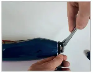
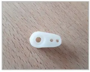
- Shorten the servo arms by sawing them off. Do not use astring cutter.
- Mount aileron servo levers at 90° angle, flap servo levers at 45° angle pointing to the end rail at neutral position.
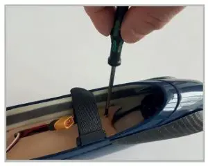
- Now the servos can already be inserted into their holders and screwed tight with the strap over them.
- Cut the foil at the slots for the control horns.
- Sand the control horns to match their mounting depth and epoxy them in place.
- Now make the linkages in the appropriate lengths. Ailerons approx. 66mm, flaps approx. 63mm.
- In order for the ailerons to deflect further upwards than downwards in accordance with the differentiation, the linkage must be set somewhat longer. The neutral position is thus relocated electronically.
- The linkages of the flaps should be adjusted so that when the flap is deflected downward, the linkage „knots“ to the servo arm, i.e. forms a 180° angle. This relieves the servo when the flap is fully deflected.
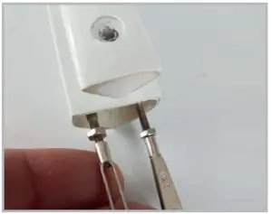
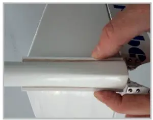
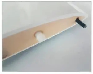
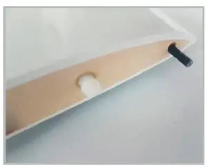
- Grind the torsion pins and glue them into the holes up to 10mm protrusion. Check the exact fit in the assembled state including the pin on the fuselage beforehand.
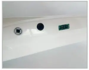
- We recommend the Multilock system for locking the wing to the fuselage. Install this according to the enclosed instructions. Alternatively, simply secure the wing with a strip of tape.

- We recommend to mount the electrical connection by means of MPX connector. This will save you cable tangles later when setting up at the airfield.


MONTAGE UND JUSTAGE / INSTALLATION AND TUNING PROCESS / INSTALLATION
- Switch on the transmitter with the model memory preset accordingly and connect the battery. Also connect the wing cables to the receiver accordingly.
- Mount the wings to the fuselage.
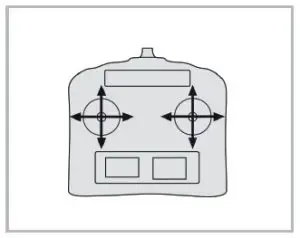
- First adjust, as far as possible, all linkages mechanically. Then check and adjust the servo running directions and travels according to the table.
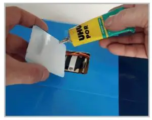
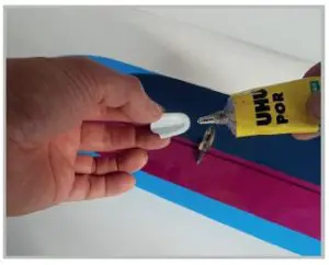
- Finally, the servo shaft covers are applied with UHU Por.
- The covers of the flap linkages are now also glued to the top.
- The CG is 83-88mm behind the leading edge. For more beginner-friendly flight behavior, initially set the CG to 83mm by moving the battery. For more performance optimized behavior, the CG can be slowly moved further back.
- Mark the exact position of the battery in the fuselage to achieve the center of gravity reproducibly later.


FLUGEMPFEHLUNG / FLIGHT RECOMMENDATIONS /
RECOMMANDATION DE VOL
- Now look for a day with suitable weather conditions for the first flight. With the mentioned settings you will be spared bad surprises. We recommend, at least on the first flight, to make the start with a starting helper
We wish you lots of fun and nice flying hours with your new Robbe SAPPHIRE and always happy landings!