![]()
052093 Electronic Measurement Device
User Manual
INTRODUCTION
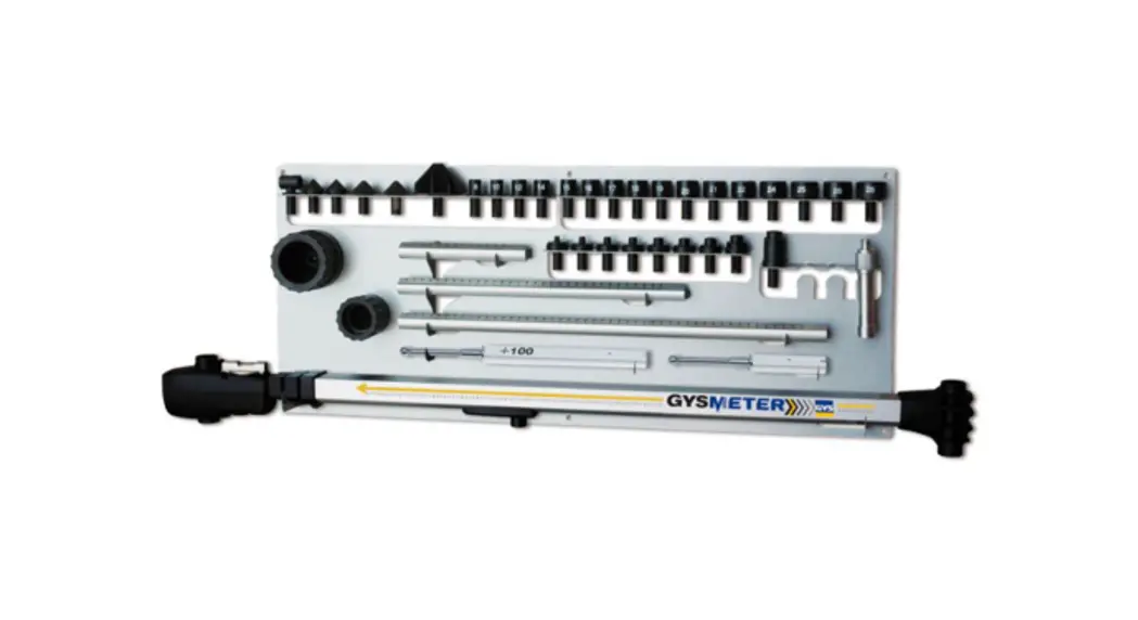
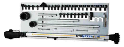
GYSMETER is an electronic measurement device designed for measuring and checking dimensions of vehicle unibody and frame.
The tool consists of the following components:
- Gysmeter
- 2 magnetic chassis attachments
- 2 datum rods
- 3 height measuring rods
- Measuring sockets and tips
- 1 panel
- Software for saving and printing the measure results, available at www.gys.fr.
The equipment described above allows measuring length in 2 dimensions. You can also compare the
symmetry in height between left and right sides, in a very effective way.
This instruction manual contains a description of the equipment and directions for its use, handling and maintenance.
IMPORTANT!
Read carefully the instructions for an optimal use of the GYSMETER equipment.
The equipment is intended for use in the auto body shop environment and in accordance with all recognized official safety procedures.
Photos and drawings used throughout these instructions depict the fundamental features and design of the product at the time of publishing and do not reflect potential future design changes.
WARNING!
Do not store or keep GYSMETER near computers, credit cards or other magnetic sensible devices, as the magnet in the chassis attachment may damage these.
MAINTENANCE
General information
The GYSMETER measuring tool is composed of a high precision electronic measuring arm, which necessitates a specific maintenance in order to maintain its performances on the long term.
Please follow all instructions and safety procedures very carefully to maintain equipment reliability and to benefit from all of its great features.
Maintenance
Clean the product after every use.
The electronic measuring arm requires a specific cleaning, and in particular the mobile parts.
Use a clean dry cloth without any liquid or detergent.
Return all parts to the wall stand after each and every use. Regularly check the measuring arm and all the accessories.
Recycling
When scrapping the product, it is important to sort all parts depending on their composition according to local disposal regulations.
Battery replacement
The digital circuit of the TECH-D measuring arm is powered by 2 x AA 1.5 Volt batteries.
Batteries should be replaced when the digital display begins to flash. It is recommended that both batteries should be replaced at the same time. The batteries should be disposed of in accordance with local disposal regulations.
Release the battery cover by hand or with a small flat blade screwdriver. 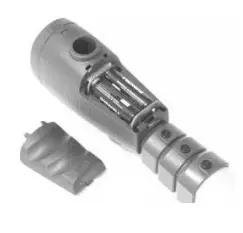
NB: the batteries should be installed according to the diagram molded on the inside of the battery compartment to ensure correct terminal polarity.
Do not use batteries with power ratings other than 1.5 Volt as this can cause the equipment to malfunction or damage the digital circuit.
GENERAL DESCRIPTION
The device is mainly composed of a telescopic measuring arm made of Aluminium and composite.
In the rear end of the tool is an attachment for height level rods. A quick release built accepts the height level rods. The magnetic chassis attachments should be snapped on the ball of the datum rods.
The front part of the measuring device is composed on one hand of the electronic measurement unit with digital display, and on the other hand of a mechanical fixing feature for each of the 3 different lengths of height measuring rods.
A level assembly is built into the top of the housing of the digital unit, for identification of the vehicle’s height differences on symmetric points, on the left and right hand side of the vehicle.
The command panel and the digital display are located on the front of the measuring device. It is on this command panel that the measurement methods should be selected by pressing the relevant buttins.
Most of the electronics is located inside the front end of the measuring device. This is also where the two AA batteries are located. The duration of the batteries is estimated to minimum 50 hours of continuous use.
For operating instructions, please refer to page 13-18
STARTING UP
NOTE! When you start using the GYSMETER, make sure the telescopic measuring arm is completely retracted !
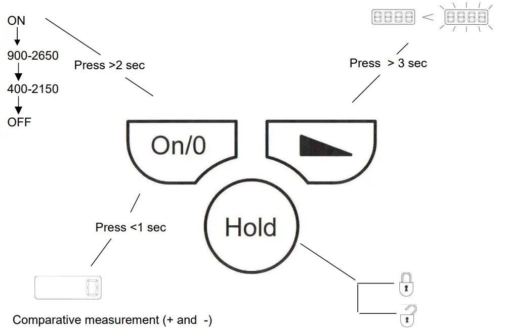
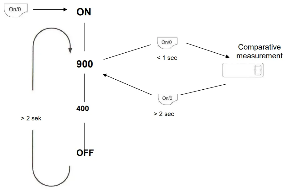
Start the GYSMETER by pressing briefly the On/O key .
The display indicates the value 900, which represents the minimum length (between the heigth calibration rod and datum heigth rod center).
Note: If display does not read 900 – switch off by holding down the On/0 key for a few seconds and restart following the above procedure.
NORMAL MODE
This is the default setting of the product after start.
Minimum – Maximum measurement range : 900-2650 mm.
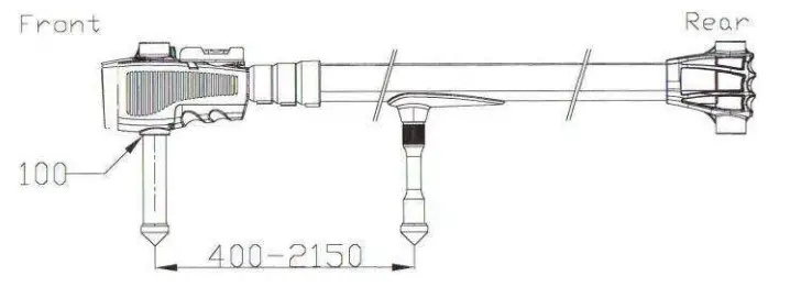
MEASUREMENT OF SHORT DISTANCES
To measure short distances, 400-2150 mm, press ![]() during 2 seconds.
during 2 seconds.
Use the tip holder that is attached underneath the measuring arm. Use this measuring method preferably in the engine compartment.
COMPARATIVE MEASUREMENTS
Pressing briefly the ![]() key, after having activated the electronics of the measuring arm, allows selecting the mode used for comparative measurements.
key, after having activated the electronics of the measuring arm, allows selecting the mode used for comparative measurements.
The display now shows 0. From this point, any change in length will register plus or minus in 1 mm gradients.
Additional comparative checking is possible by repeating the above procedure at any time during comparative checking.
FREEZE A MEASURED VALUE![]() Press the HOLD key to freeze a measured value in the display. Press it a second time to cancel this operation.
Press the HOLD key to freeze a measured value in the display. Press it a second time to cancel this operation.
DISPLAY BRIGHTNESS![]() Hold this key to increase the display brightness – release this key when the required setting has been obtained.
Hold this key to increase the display brightness – release this key when the required setting has been obtained.
ENERGY SAVING FUNCTION
The display will automatically shut down after 5 minutes and will be activated again at the slightest movement of the measuring arm.
SHUT OFF FUNCTION
The electronic control unit will shut down all circuits after 90 minutes of non operation.
The measuring arm can also be switched off manually by pressing the ![]() key for over 3 seconds.
key for over 3 seconds.
DISPLAY FONCTIONS
ACCESSORIES
Height level rods
The measuring tool includes 2 height level rods of two different lengths.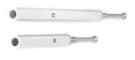
Magnetic holder
This magnetic holder is developed to suit most vehicle models on the market. Use it when a round or oval hole <Ø35 mm is specified as the zero point on the vehicle dimension data sheet. 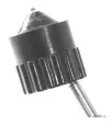
Height measuring rods
3 height rods are included.
Rod height is determined by the data sheet and should allow for the specified reading to be observed when the rod has been locked in place on the measuring arm.
Insert the rod into the measuring head at the front end of the measuring arm. Position the flat side of the rod towards the “release” mark, set it at the desired height and secure by twisting it to the “lock” position.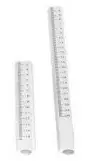
Level
On the measuring head is a level to compare height differences. 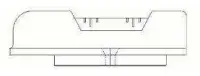
Measuring sockets and tips
GYSMETER includes:
– 5 measuring tips (2 x Ø25, 2 x Ø35 mm and 1 x Ø60 mm)
– 16 sockets sized from 10-26 mm
– 9 M201 adaptors 6-18
– 1 90° holder
Sockets and tips snap into the top of the height measuring rods.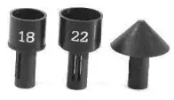
TECHNICAL SPECIFICATIONS
- The precision of the level will depend upon the extension length of the measuring arm.
- Refer to the table below for the height tolerances :
| Extension in mm | Height tolerance in mm |
| 900 | approx. 0,5 |
| 1800 | approx. 1,0 |
| 2650 | approx. 1,5 |
- Measuring range:
– Normal measure: from 900 to 2650mm
– Short measure: from 400 to 2150mm - Datum rods’ difference in height = 100 mm
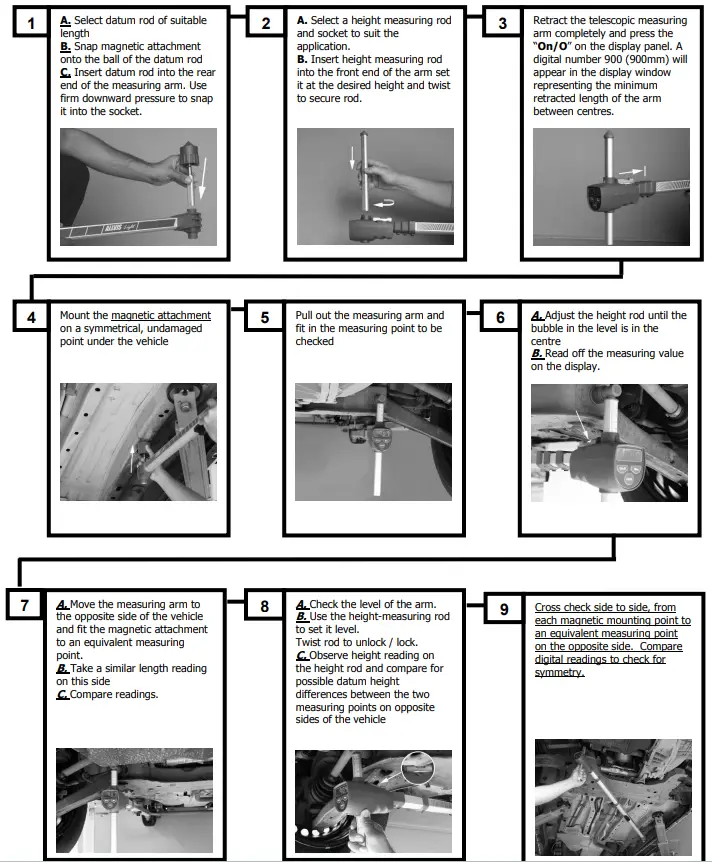
MEASURING
The technician should have a clear understanding of the damage on the vehicle before starting to use the GYSMETER measuring tool.
Being well informed and aware of specific structural damage to the vehicle beforehand will highlight possible faults or inconsistencies in measurement values on data sheets at an early stage, also incorrect mounting or measuring points selected by mistake.
When in doubt check this manual thoroughly, and if the problem persists, contact your GYSMETER distributor.
Mounting the magnetic holder
Make sure that the mounting points on both sides of the vehicle are in the right location, and that they have been cleaned.
Select a suitable datum rod and snap on the magnetic adaptor on the ball at the extremity. Check that the attachment is in the selected mounting position. Make sure that the magnetic attachment is firmly positioned and that it is not loose.
Remove the magnetic holder with height calibration rod and mount it on the holder at the rear end of the measuring arm. Use firm downward pressure to click the rod in place. 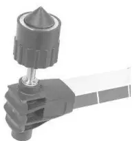
Choosing the appropriate attachment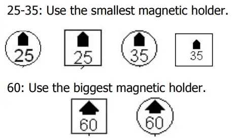 Length measuring
Before starting to measure it is important to calibrate the measuring arm. This is done by compressing the arm completely altogether and pressing the ON/0 key until the display switches off. With the measuring arm still compressed press the ON/0 key and the digital number 900 (900mm) will appear. The measuring tool will now always start measuring from 900 mm. If during measuring operations any doubt exists about the operation of the measuring arm, repeat the above procedure.
- Read the height dimension given on the datasheet and select a suitable height measuring rod and socket.
- Push the height measuring rod and adaptor into the measuring tool and set it to the height dimension given on the data sheet.
- Mount the magnetic holder in the intended attachment point under the vehicle. Pull out and adjust the measuring tool so that the selected measurement point can be reached. It can be advantageous here to use the hold feature to freeze the measurement value, especially if it is difficult to see the display while measuring. Press the HOLD key briefly to freeze the measurement value. To return, press the HOLD key again briefly.
- Read the measuring arm’s display and compare the length measurement value with the value on the data sheet. (No 1and 4)
It can be advantageous here to enter the measured value in the data sheet table in order to create a before or after report.
Repeat the same procedure on the other side of the vehicle. Note that the vehicle can have different measurement values for the right and left side.
Symmetry measuring (cross-measuring)
Before starting to measure it is important to check the setting of the measuring arm, see p.15 Measuring symmetry of a vehicle does not differ in any significant extent from the length measuring (p.15). Symmetry measuring uses basically the same procedure.
IMPORTANT: NEVER measure symmetry and check height deviations at the same time. The reason for this is that the height measurement value can be affected by the lateral inclination of the vehicle. It is, however, important that the height measuring rod is adjusted to the same height applicable to length measuring.
In all other aspects, the same procedure as in length measuring applies.
- Read the height dimension given on the datasheet and select a suitable height rod. Mount the height rod in the measuring head.
- Mount the given socket/tip at the top of the height rod or the next even numbered socket if the datasheet shows a socket with uneven number.
- Read the value given on the display and compare it with the values on the datasheet.
- Mount the magnetic attachment on the chosen magnet point on the vehicle. Pull out and adjust the measuring arm so that the selected measurement point can be reached.
It can be advantageous here to use the hold feature to freeze the measurement value, especially if it is difficult to see the display while measuring. Press the HOLD key briefly to freeze the measurement value. To return, press the HOLD key again briefly. - Read the measuring arm’s display and compare the symmetry (cross) measurement value with the value on the data sheet.
(It can be advantageous here to enter the measured value in the data sheet table in order to create a before or after report.)
Repeat the same procedure on the corresponding measurement points on the other side of the vehicle (measuring line no 3).
Note that the vehicle can have different measurement values for the right and left side, depending on the design of the vehicle.
Comparing heights
You can compare heights with the help of the level included on the arm.
When comparing heights, there are several important points to bear in mind:
- • Place the vehicle as horizontal as possible, from one side to the other (laterally), or this can have an influence on the accuracy of the height measurement.
- Always measure the height at the same time as length (measure parallel to the vehicle’s central line).
- The water level on the arm is fixed which often means that it is not on the same level as the vehicle to check. This means that the measuring values stated for the height rod on the datasheets are intended for the setting of the arm when length measures are done.
Height measurements by comparison :
Adjust the height rod until the bubble of the level is at the exact centre (this measure shall be made on lines 1 and 4 of the datasheet only).
Move the arm over to the other side of the vehicle, setting it on the corresponding points. If the bubble is not in the centre, there might be a possible height difference.
Read off the height rod scale and adjust up or down to be able to read the difference in height.
SHORT DISTANCE MEASUREMENTS
The measuring tool features an adaptor for ”short distance measurements”.
Screw the holder in the measuring arm and choose the appropriate socket/tip.
The measures can now be taken from 400 to 2150 mm.
NOTE! Change the measuring range to 400-2150mm by pressing the ON/O key for 2 seconds. Assemble a 100mm height rod in the lower edge of the measuring tool.
GYS TECH SOFTWARE
The GYSTECH software can be downloaded by clicking at the following address : http://www.gys-welding.com/distFiles/GYSMETER_install.exe
As the software starts up, click on the flag of the chosen language, then on START.
The below window shows up:
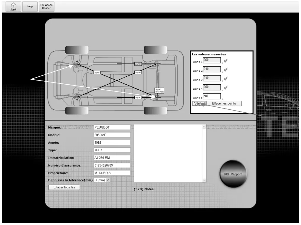
- Select 2 points diagonally to make the line 1 show up. The software will automatically generate the other lines.
- Fill in the appropriate fields with the measures taken.
- Click on « verify »
- Fill in the information of the measured vehicle
- Click on « PDF Report » to generate a report, which can be printed, saved, and sent by email.
SPARE PARTS
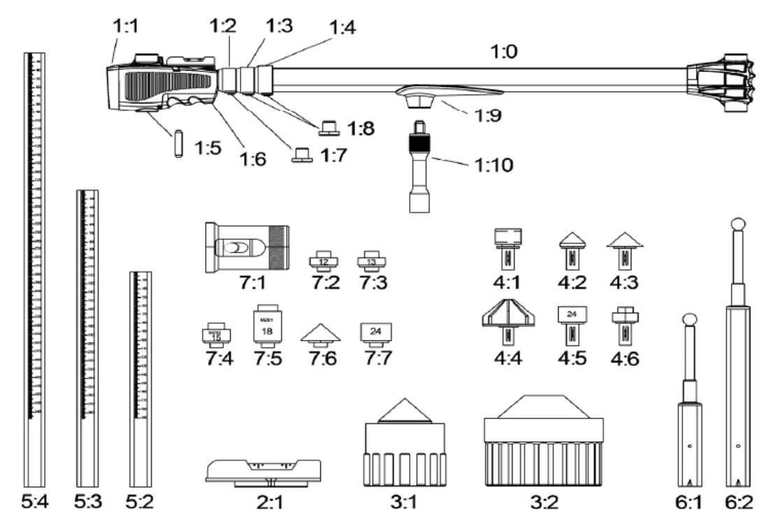
| 1:05 | AVP1361 | Friction stick |
| 1:06 | XME13130 | Battery cover |
| AVP1450 | Battery | |
| 1:07 | AVP1320 | Locking for collar |
| 1:08 | AVP1320-2 | Locking for collar |
| 1:09 | EMK1404 | Slide |
| 1:10 | EMK1403 | Tip holder for slide |
| 2:01 | XME1410 | Level |
| 3:01 | XME1480 | Chassis attachment 035 |
| 3:02 | XME222 | Chassis attachment 060 |
| 4:01 | XME3100 | Tip holder 90° |
| 4:02 | XME3000 | Measuring tip 025 |
| 4:03 | XME2900 | Measuring tip 035 |
| 4:04 | XME2800 | Measuring tip 060 |
| 4:05 | XME1390 | Socket 010-28 (state no when order) |
| 4:06 | XME2705 | Adaptor M201 6-18 (state no when order) |
| 5:02 | AVP1190 | Measuring rod 185 |
| 5:03 | AVP1200 | Measuring rod 285 |
| 5:04 | AVP1210 | Measuring rod 450 |
| 6:01 | AVP1110 | Datum rod |
| 6:02 | AVP1130 | Datum rod +100 |
| 7:01 | AVP1470 | Chassis attachment 90° |
| 7:02 | AVP1485 | Adaptor 12 |
| 7:03 | AVP1490 | Adaptor 13 |
| 7:04 | AVP1500 | Adaptor 15 |
| 7:05 | AVP1510 | Adaptor 18 |
| 7:06 | AVP1521 | Measuring tip short 035 |
| 7:07 | AVP1540 | Socket short 10-26 (state no when order) |
| AVA111 | Complete truck adaptor kit | |
| XME1263 | Allvis Light storage case (complete) | |
| XME1170 | Storage case side |
QUICK GUIDE
Measuring without data sheet
ICONOS
| – Caution ! Read the user manual. | |
| – Use gloves that guarantee electrical and thermal insulation. | |
| – Use a noise helmet if the sanding reaches a noise level above the authorized limit (the same applies to anyone in the work area). | |
| – Mandatory safety glasses. | |
| – Equipment in compliance with British requirements. The British Declaration of Conformity is available on our website (see home page). | |
| – CMIM : Moroccan Certification | |
 | – Devicecompliant with European directives. The certificate of compliance is available on our website (www.gys-welding.com) |
| – This product should be recycled appropriately. |


