
ZWAVE-SELECTION
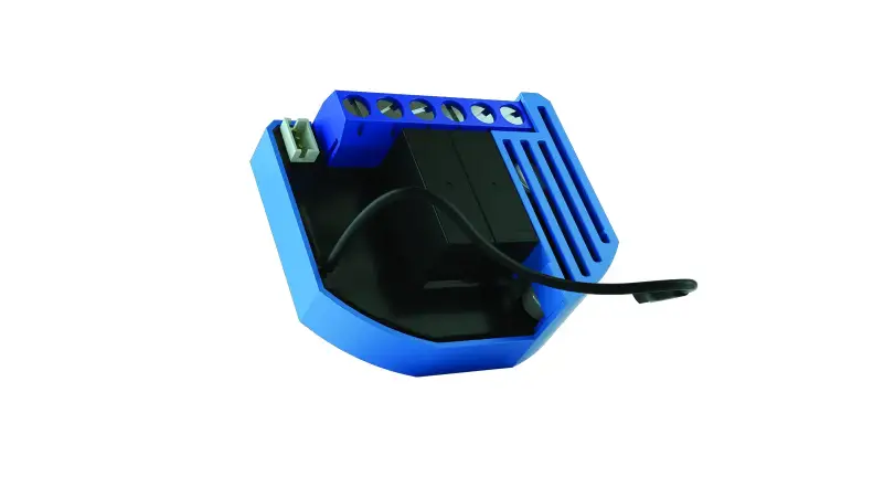
Roller Shutter
SKU: ZWSERSH

Quickstart
This is a
Roller Shutter
for
Europe.
To run this device please connect it to your mains power supply.
To add this device to your network execute the following action:
Important safety information
Please read this manual carefully. Failure to follow the recommendations in this manual may be dangerous or may violate the law.
The manufacturer, importer, distributor and seller shall not be liable for any loss or damage resulting from failure to comply with the instructions in this manual or any other material.
Use this equipment only for its intended purpose. Follow the disposal instructions.
Do not dispose of electronic equipment or batteries in a fire or near open heat sources.
What is Z-Wave?
Z-Wave is the international wireless protocol for communication in the Smart Home. This
device is suited for use in the region mentioned in the Quickstart section.

Z-Wave ensures a reliable communication by reconfirming every message (two-way
communication) and every mains powered node can act as a repeater for other nodes
(meshed network) in case the receiver is not in direct wireless range of the
transmitter.
This device and every other certified Z-Wave device can be used together with any other
certified Z-Wave device regardless of brand and origin as long as both are suited for the
same frequency range.
If a device supports secure communication it will communicate with other devices
secure as long as this device provides the same or a higher level of security.
Otherwise it will automatically turn into a lower level of security to maintain
backward compatibility.
For more information about Z-Wave technology, devices, white papers etc. please refer
to www.z-wave.info.
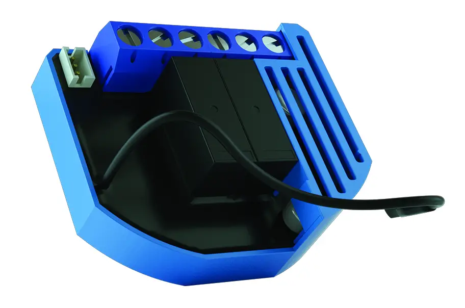
Product Description
This Z-Wave module is used to control the motor of blinds, rollers, shades, venetian blinds, etc … The module can be controlled either through a Z-Wave network or through the wall switch. Precise positioning is supported for motors equipped with mechanical or electronic end switches. The module is designed to be mounted inside a “flush mounting boxâ€, hidden behind a traditional wall switch. Module measures power consumption of motor and support connection of digital temperature sensor. It is designed to act as repeater in order to improve range and stability of Z-wave network.
Prepare for Installation / Reset
Please read the user manual before installing the product.
In order to include (add) a Z-Wave device to a network it must be in factory default
state. Please make sure to reset the device into factory default. You can do this by
performing an Exclusion operation as described below in the manual. Every Z-Wave
controller is able to perform this operation however it is recommended to use the primary
controller of the previous network to make sure the very device is excluded properly
from this network.
Reset to factory default
This device also allows to be reset without any involvement of a Z-Wave controller. This
procedure should only be used when the primary controller is inoperable.
– Press push button I1 five times within 3s (5 times” change switch state within 3 seconds) in the first 60″ seconds after the module is connected to the power” supply or”
– Press service button S (only applicable for 24 V SELV” supply voltage) for more than 6 second.
Safety Warning for Mains Powered Devices
ATTENTION: only authorized technicians under consideration of the country-specific
installation guidelines/norms may do works with mains power. Prior to the assembly of
the product, the voltage network has to be switched off and ensured against re-switching.
Installation
“· Do not shorten the antenna.
Electrical diagram 230VAC
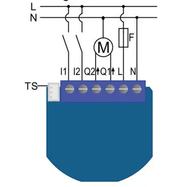
TS… Terminal for digital temperature sensor (only for” Flush Shutter module compatible digital” temperature sensor, which must be ordered” separately).
Inclusion/Exclusion
On factory default the device does not belong to any Z-Wave network. The device needs
to be added to an existing wireless network to communicate with the devices of this network.
This process is called Inclusion.
Devices can also be removed from a network. This process is called Exclusion.
Both processes are initiated by the primary controller of the Z-Wave network. This
controller is turned into exclusion respective inclusion mode. Inclusion and Exclusion is
then performed doing a special manual action right on the device.
Inclusion
Exclusion
– Press service button S (only applicable for 24 V SELV” supply voltage) for more than 6 second.
Auto-Inclusion
Beside the standard inclusion this devices supports the so called auto inclusion.
Right after powering up the device remains in inclusion state and can be included by
(any) gateway without further actions on the device itself. The auto inclusion mode will
time out after some time.
Product Usage
Automatic calibration
Automatic calibration is a process during which the Flush” Shutter learns the position of the limit switches.”
Shutter positioning calibration
(par. 71 set to 0)
There are two procedures of calibration.
Calibration through main controller UI
4) Set the parameter 78 (Forced Flush Shutter calibration)” value to 0.”
Calibration through the inputs I1 and I2
4) Quick press the switch/push-button connected to I1″ input and wait until the Shutter reach upper limit switch.
6) By default full turn movement is set to 1,5s. If this time” is too long (if after slates full cycle Shutter starts” moving up or down), decrease this time defined with” parameter 72. If this time is to short (if slats will not” turn for full cycle), increase this time defined with” parameter 72.
Keeping pressed push-button (>2s) connected to I2 (down),” initiates down movement, until push-button is released.
Keeping pressed push-button (for time > (full turn slates” time +2s)) connected to I1 (up), initiates up movement, until” push-button is released.
Clicking push-button (for time < full turn slates time-par.72)” connected to I1 (up), initiates Shutter up movement.
Keeping pressed push-button (for time > full turn slates” time-par.72) connected to I1 (up), initiates Shutter up” movement, until the push-button is released.
Keeping pressed push-button (for time > (full turn slates” time +2s)) connected to I2 (down), initiates down” movement, until push-button is released.
Quick trouble shooting
Here are a few hints for network installation if things dont work as expected.
- Make sure a device is in factory reset state before including. In doubt exclude before include.
- If inclusion still fails, check if both devices use the same frequency.
- Remove all dead devices from associations. Otherwise you will see severe delays.
- Never use sleeping battery devices without a central controller.
- Dont poll FLIRS devices.
- Make sure to have enough mains powered device to benefit from the meshing
Association – one device controls an other device
Z-Wave devices control other Z-Wave devices. The relationship between one device
controlling another device is called association. In order to control a different
device, the controlling device needs to maintain a list of devices that will receive
controlling commands. These lists are called association groups and they are always
related to certain events (e.g. button pressed, sensor triggers, …). In case
the event happens all devices stored in the respective association group will
receive the same wireless command wireless command, typically a ‘Basic Set’ Command.
Association Groups:
Group NumberMaximum NodesDescription
| 1 | 1 | default reporting group (reserved for the main” controller) |
| 2 | 16 | basic on/off (triggered at change of the input I1″ state and reflecting its state)” |
| 3 | 16 | basic on/off (triggered at change of the input I2″ state and reflecting its state) |
| 4 | 16 | basic on/off (triggered at sensing moving direction” of roller: up=255, down=0) |
| 5 | 16 | basic on/off (triggered at reaching roller position:” bottom=255, top=0) |
| 6 | 16 | basic on/off (triggered at reaching roller position:” bottom=255, not bottom=0) |
| 7 | 16 | multilevel set (triggered at changes of value of the” Flush Shutter DC position) |
| 8 | 16 | multilevel set (triggered at changes of value of” slats tilting position) |
| 9 | 16 | multilevel sensor report (triggered at change of” temperature sensor) |
Configuration Parameters
Z-Wave products are supposed to work out of the box after inclusion, however
certain configuration can adapt the function better to user needs or unlock further
enhanced features.
IMPORTANT: Controllers may only allow configuring
signed values. In order to set values in the range 128 … 255 the value sent in
the application shall be the desired value minus 256. For example: To set a
parameter to 200 it may be needed to set a value of 200 minus 256 = minus 56.
In case of a two byte value the same logic applies: Values greater than 32768 may
needed to be given as negative values too.
Parameter 10: Activate/deactivate functions ALL ON / ALL OFF
Flush Shutter responds to commands ALL ON / ALL OFF” that may be sent by the main controller or by other controllers belonging to the system.
Size: 2 Byte, Default Value: 255
SettingDescription
| 0 | ALL ON is not active ALL OFF is not active |
| 1 | ALL ON is not active ALL OFF active |
| 2 | ALL ON active ALL OFF is not active |
| 255 | ALL ON active, ALL OFF active. |
Parameter 40: Power reporting in Watts on power change for Q1 or Q2
Set value means percentage, set value from 0 – 100 = 0% – 100%.”
NOTE: if power changed is less than 1W, the report is not” send (pushed), independent of percentage set.
Size: 1 Byte, Default Value: 1
SettingDescription
| 0 | reporting disabled |
| 1 – 100 | 1% – 100% Reporting enabled. Power report is send (push) only when actual power (in Watts) in real time changes for more than set percentage comparing to previous actual power in Watts, step is 1%. |
Parameter 42: Power reporting in Watts by time interval for Q1 or Q2
Set value means time interval (0 – 32767) in seconds,” when power report is send.
Size: 2 Byte, Default Value: 300
SettingDescription
| 0 | reporting disabled |
| 1 – 32767 | 1 second – 32767 seconds. Reporting enabled, power report is send with time interval set by entered value. |
Parameter 71: Operating modes
This parameter defines selection between two available” operating modesNOTE: After parameter change, first exclude module” (without setting parameters to default value) then wait at” least 30s and then re include the module!
Size: 1 Byte, Default Value: 0
SettingDescription
| 0 | Shutter mode |
| 1 | venetian mode (up/down and slate rotation) |
Parameter 72: Slats tilting full turn time
This parameter defines the time necessary for slats to” make full turn (180 degrees).
NOTE: If time set is too high, this will result that after full turn, Shutter will start move up or down, for time remaining.
Size: 2 Byte, Default Value: 150
SettingDescription
| 0 | tilting time disabled |
| 1 – 32767 | 0,01seconds – 327,67 seconds |
Parameter 73: Slats position
This parameter defines slats position after up/downmovement through Z-wave or push-buttons.
Size: 1 Byte, Default Value: 1
SettingDescription
| 0 | Slats return to previously set position only in case of Z-wave control (not valid for limit switch positions). |
| 1 | Slats return to previously set position in case of Z-wave control, push-button operation or when the lower limit switch is reached. |
Parameter 74: Motor moving up/down time
This parameter defines Shutter motor moving time of” complete opening or complete closing.
NOTE: Important is that the reference position to manually” set moving time is always Shutter lower position! Set parameter 74 to 0 and move the Shutter (using” up/down push buttons or main controller UI) to the lowest” desired position. On this Shutter position, set parameter 74″ to time for complete opening or complete closing. At this” point Shutter can be moved up (open) for set time, but can‘t” be moved down because this position is already set as” lower Shutter position.To change Shutter lower position below already set” (manual recalibration), parameter 74 must be set to 0 and” repeat the procedure described above.” In case Shutter has limit switches, but anyhow you would” like to limit opening/closing position by time, you can still do” it. In case you put time that is longer that opening/closing” real time limited by limit switches, Shutter will stop at limit” switch, but the module relay will switch off after define time,” not by Shutter limit switch. Take in consideration that in thiscondition, the positioning with slider through UI will not” show correct Shutter position.
Size: 2 Byte, Default Value: 0
SettingDescription
| 0 | moving time disabled (working with limit switches) |
| 1 – 32767 | 0,1seconds – 3276,7seconds |
Parameter 76: Motor operation detection
Power threshold to be interpreted when motor reach thelimit switch.
Size: 1 Byte, Default Value: 10
SettingDescription
| 1 – 127 | 1-127 W. The value 0 means reaching a limit switch will not be detected. |
Parameter 78: Forced Shutter calibration
By modifying the parameters setting from 0 to 1 a Shutter” enters the calibration mode.
Size: 1 Byte, Default Value: 0
SettingDescription
| 1 | Start calibration process (when calibration process is finished, completing full cycle – up, down and up, set the parameter 78 (Forced Shutter calibration) value back to 0. |
Parameter 85: Power consumption max delay time
This parameter defines the max time before motor power” consumption is read after one of the relays is switched” ON. If there is no power consumption during this max time” (motor not connected, damaged or requires higher time to” start, motor in end position) the relay will switch OFF. Time” is defined by entering it manually.
Size: 1 Byte, Default Value: 0
SettingDescription
| 3 – 50 | 0,3seconds – 5seconds (100ms resolution) |
Parameter 90: Time delay for next motor movement
This parameter defines the minimum time delay between” next motor movement (minimum time between switching” motor off and on again).
Size: 5 Byte, Default Value: 1
SettingDescription
| 1 – 30 | 0,1seconds – 3seconds (100ms resolution) |
Parameter 110: Temperature sensor offset settings
Set value is added or subtracted to actual measured value” by sensor.
Size: 2 Byte, Default Value: 32536
SettingDescription
| 1 – 100 | value from 0.1 “°C to 10.0 “°C is added to actual measured temperature. |
| 1001 – 1100 | value from -0.1 “°C to -10.0 “°C is subtracted to actual measured temperature. |
Parameter 120: Temperature sensor reporting
If digital temperature sensor is connected, module reports” measured temperature on temperature change defined by” this parameter.
Size: 1 Byte, Default Value: 5
SettingDescription
| 0 | Reporting disabled |
| 1 – 127 | 0,1″°C – 12,7″°C, step is 0,1″°C |
Technical Data
| Dimensions | 0.0206000×0.0140000×0.0388000 mm |
| Weight | 27 gr |
| Hardware Platform | ZM5202 |
| IP Class | IP 20 |
| Voltage | 230 V |
| Load | 2x 1KW |
| Device Type | Roller Shutter |
| Generic Device Class | Multilevel Switch |
| Specific Device Class | Motor Control Device (C) |
| Firmware Version | 05.00 |
| Z-Wave Version | 04.05 |
| Certification ID | ZC10-17045565 |
| Z-Wave Product Id | 0x0159.0x0003.0x0052 |
| Frequency | Europe – 868,4 Mhz |
| Maximum transmission power | 5 mW |
Supported Command Classes
- Basic
- Switch Binary
- Switch Multilevel
- Switch All
- Meter
- Association Grp Info
- Device Reset Locally
- Zwaveplus Info
- Configuration
- Manufacturer Specific
- Powerlevel
- Association
- Version
- Multi Channel Association
Controlled Command Classes
- Basic
- Switch Multilevel
Explanation of Z-Wave specific terms
- Controller — is a Z-Wave device with capabilities to manage the network.
Controllers are typically Gateways,Remote Controls or battery operated wall controllers. - Slave — is a Z-Wave device without capabilities to manage the network.
Slaves can be sensors, actuators and even remote controls. - Primary Controller — is the central organizer of the network. It must be
a controller. There can be only one primary controller in a Z-Wave network. - Inclusion — is the process of adding new Z-Wave devices into a network.
- Exclusion — is the process of removing Z-Wave devices from the network.
- Association — is a control relationship between a controlling device and
a controlled device. - Wakeup Notification — is a special wireless message issued by a Z-Wave
device to announces that is able to communicate. - Node Information Frame — is a special wireless message issued by a
Z-Wave device to announce its capabilities and functions.


