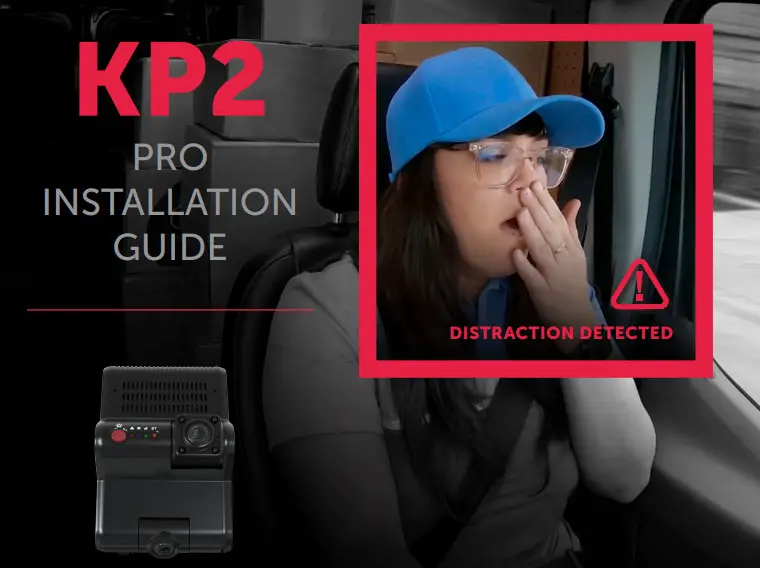
![]() KP2 Pro 4G LTE Fleet Telematics Dash Cam
KP2 Pro 4G LTE Fleet Telematics Dash Cam
Installation Guide
 |  |

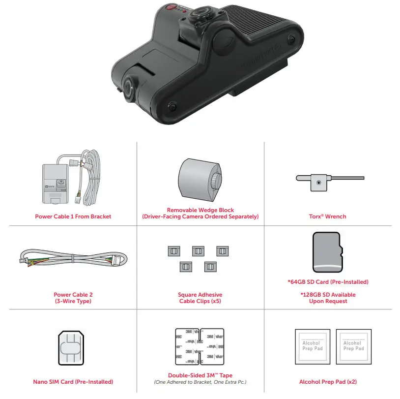
PACKAGE CONTENTS
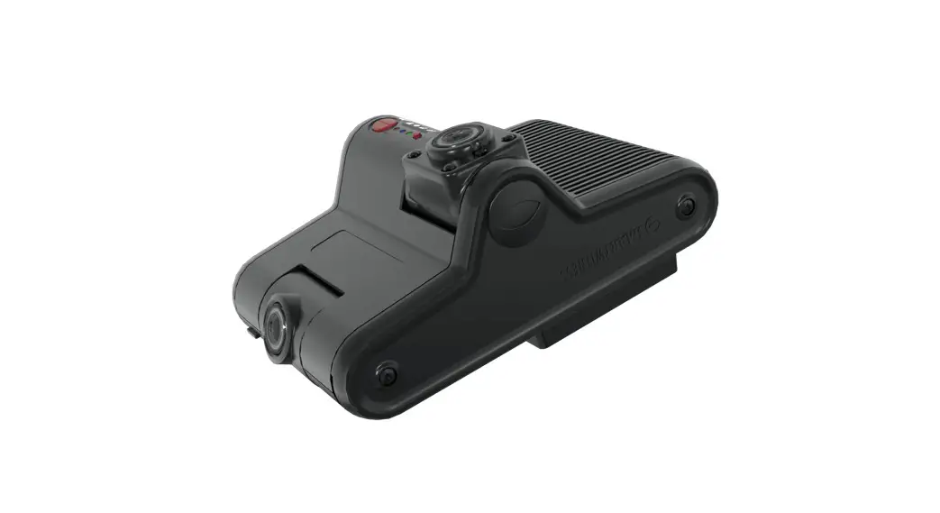
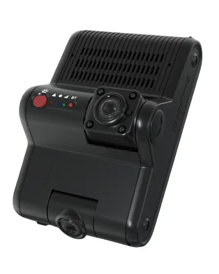
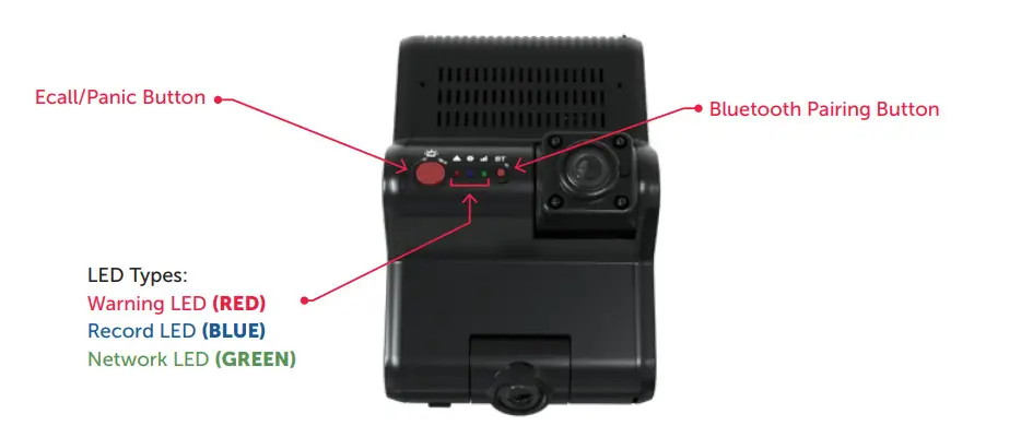
KP2 FEATURE REFERENCE
FRONT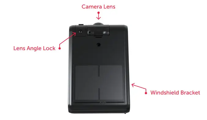
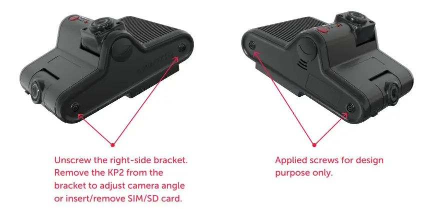
SIDE
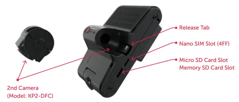
SIDE COVER OPEN
BACK
HOW TO INSTALL YOUR KP2
Prepare Your KP2
DISCLAIMER
The KP2 installation featured in this guide is designed for professional installation. SmartWitness assumes installers possess knowledge of current, generally accepted industry installation standards and practices.
The process outlined in this document accounts for driver positioning on the left side of the vehicle.
Please adjust the installation accordingly if you’re working with driver positioning on the vehicle’s right side.
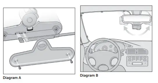
- Use the Torx® wrench provided in the package contents to open the side cover of the device. You’ll notice that both the microSD and SIM cards come pre-installed.
See Diagram A.
- Keep the side panel open. It allows you to remove the KP2 from its mount and adjust the driver- and road-facing cameras. Prep the cameras for adjustments.
• Loosen the KP2’s top screw (for the road-facing lens) with the Torx wrench.
• The driver-facing camera has a release tab next to the lens.
Note: You must order the KP2’s driver-facing camera as a separate accessory.
White-label KP2s are exceptions. - Go to your vehicle, and hold your KP2 where you’ll mount the bracket. Your KP2 placement should reduce the windshield’s blind-spot footprint, with the road-facing camera within the top 2″ of the wiper path. The device should reside close to the center of the windshield. See Diagram B.
Note: The driver-facing lens needs complete visibility of the driver, without any physical or visual obstructions. Ensure your vehicle’s sun visor doesn’t complicate camera visibility. - While holding the KP2 in place, rotate each camera until they’re at the desired angle.
- Remove the protective decals from each lens.
- Use the Torx wrench to tighten the top screw on the KP2 and lock the road-facing camera’s position.
Once you’ve secured the road-facing camera, please go on to Attach Your Camera to the Windshield.
Attach Your Camera to the Windshield
Your vehicle’s windshield temperature shouldn’t be too hot or cold. SmartWitness recommends installing your KP2 in moderate temperatures (50°F~80°F).
If in severely cold weather, use the vehicle defrosters to warm and dry out the windshield.
Ensure your windshield is dry and has no chips or cracks before installation. If the windshield is compromised,
device application may cause chips or cracks to spread.
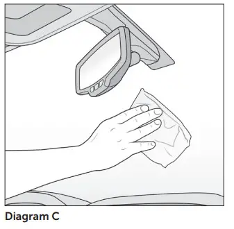
- Clean the windshield with your alcohol wipe. See Diagram C. Allow time to dry.
- Remove any film left over from the solution.
- Remove the plastic from the tape on the mounting bracket.
- When attaching the KP2 to the windshield, position the bracket so it’s flush with the windshield.
Note: When installing the KP2 in a truck, FMCSA mandates that the device’s
camera is in the top 2″ of the windshield wiper sweep. - Apply your KP2 to the windshield, and maintain pressure for at least 30 seconds.
- After mounting your KP2, use the Torx® wrench to re-secure the device’s side cover. This locks both camera positions in place.
Diagram C
- Go outside the vehicle, and check whether 80%–90% of the tape’s surface area connects with the glass.
Momentarily apply pressure where the camera doesn’t connect to the glass (if necessary).
Once the device is correctly attached to the windshield, continue to Connect the KP2 to Your Vehicle’s Power Source.
Connect the KP2 to Your Vehicle’s Power Source
If you are not a professional technician, click here to request installation from an approved SmartWitness installer. By continuing this process without a certified installer, you accept the ramifications of tampering with your vehicle’s power source.
- Turn off your vehicle.
- Take your main power cable, and place it where it’ll reside alongside the vehicle’s headliner and A-pillar. This shows you where to route the cable and how much slack to leave to connect the adapter cable to the vehicle’s power source.
- Clean the space where the cable clips will reside with an alcohol wipe.
Allow time to dry. - Once the windshield is dry, attach clips where you’ll place the cable.
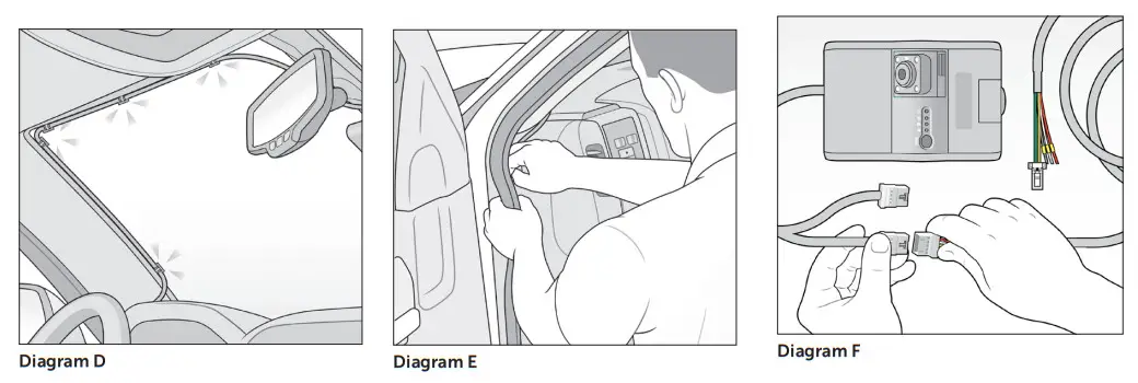
Ensure the clips are evenly spaced, around 6″ apart. Keep the opening of the clips face up, and ensure the cable remains taut. - Slide the power cable from the bracket into the clips. Your cable should look like Diagram D.
- Route the power cable around the side and behind interior panels or weather stripping to secure it. See Diagram E. The cable should fall near the vehicle’s fuse box/power source.
- Attach the KP2 main power cable to one of the compatible power adapter options. Let’s use the bare 3-wire connection adapter provided in the box for this walk-through. See Diagram F.
 Note: SmartWitness provides optional power adapter accessories separately.
 - Identify each connection wire on the 3-wire adapter: black, white, and red.
Note: Ensure your 3-wire connection has fuses attached to the red and white wires within 4″ of the power source. This is a requirement that protects both your device and your vehicle. - Connect each wire to its associated power source.
• Black – ground or battery (-)
• White – true ignition or ACC
• Red – power or battery (+)
Go to How to Test Your Installation to ensure you’ve properly applied power to your device.
 Note: SmartWitness provides optional power adapter accessories separately.
HOW TO TEST YOUR INSTALLATION
After installing the KP2 in your vehicle, test whether it is operational.
- Turn on your vehicle. Your camera should power on.
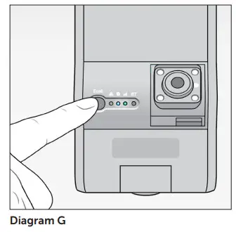
- You’ll see a Red/Blue/Green light sequence during your camera’s boot-up process (see LED Reference Table).
- After your camera completes the boot-up process, check for a solid Blue light. This indicates proper operation and recording.
- Check for a Greenlight that remains on, indicating connectivity.
- Watch for a Blue light. After 5 minutes, if both the Green and Blue lights don’t remain on, an error has occurred. See Diagram G.

TROUBLESHOOTING ERROR SCENARIOS
If your KP2 has:
- Solid Red, Blue and Green lights, then a camera isn’t receiving a video signal. Check your camera’s connection.
- A solid Blue light, but the Green light is blinking or is off, then clean and correctly reinsert your SIM card.
– If the Green light still blinks, this is a configuration or server issue that requires SmartWitness support. - A Red blinking light, then there is an SD card error or corruption. Contact your local distributor or SmartWitness support to repair or replace your SD card.
- A solid Red light, then your device isn’t receiving enough voltage or amperage. Check the output of your power source or your ground (black wire) connection.
If your KP2 install is operational, please move on to How to Calibrate Your G-Sensor.
HOW TO CALIBRATE YOUR G-SENSOR
Park your vehicle on a flat surface for calibration.
After your camera boots up, press the G-sensor calibration button. This is the small Red button to the right of the e-call/panic button.
You’ll hear a beep, and the KP2 LED light will blink briefly to indicate that the G-sensor calibration has registered.
You’ve completed the first steps of your KP2 installation. To adjust your settings, continue to How to Configure KP2 Settings.
HOW TO CONFIGURE KP2 SETTINGS
To finalize your installation and onboard your device, scan the QR code. Download and open the app. Scan your device’s IMEI label, and follow the walk-through featured below.
Access KP2 Installation App
 https://play.google.com/store/apps/details?id=com.smartwitness.kp2installer&hl=en_US&gl=US
https://apps.apple.com/app/kp2-installer/id1610816200
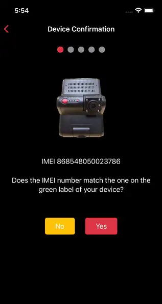 | 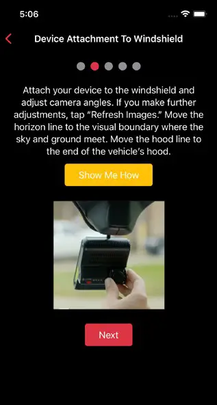 |
| 1. Ensure the IMEI code in the app matches your device’s IMEI. If there isn’t a match, click No and contact SmartWitness support. If there’s a match, click Yes to continue. | 2. Read the instructions to understand more about your vehicle’s “Horizon” and “Hood” lines. Click Show Me How for a brief video walk-through of the device attachment process. |
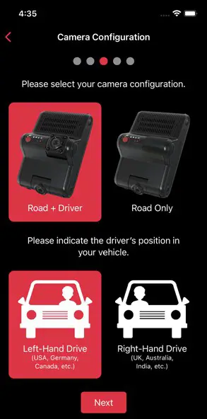 | 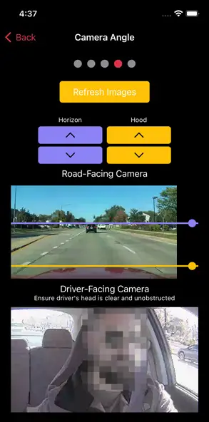 |
| 3. Select your KP2 camera configuration. Choose the driver’s side of the vehicle (from the perspective of the front of the vehicle). Click Next to set your vehicle’s “Horizon” and “Hood” lines. | 4. If you adjust either camera, click Refresh Images to update road- and driver-facing camera images. Use the arrows to adjust your vehicle’s “Horizon” and “Hood” lines. Ensure your “Hood” line is in the bottom one-fourth of your image. Scroll down and click Next to save the “Horizon” and “Hood” lines. |
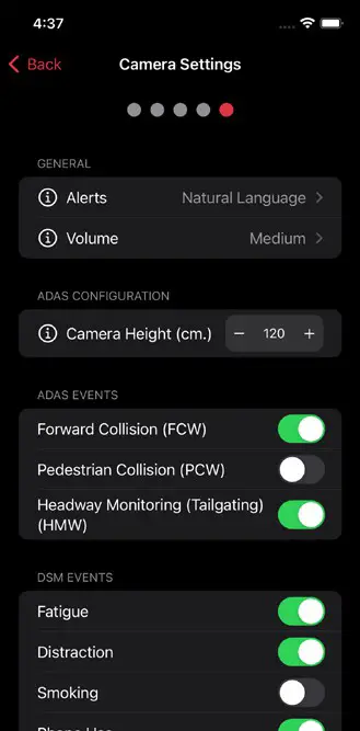 | 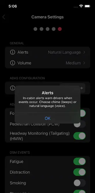 |
| 5. Choose preferences for in-cabinets, an alert’s volume level or activation of different ADAS and DSM events. | 6. If you’re unaware of a setting’s function, click the info icon to learn more. Pay close attention to Camera Height. Enter an even interval value (e.g., 190 cm), not an odd interval value (e.g., 205 cm, 213 cm). |
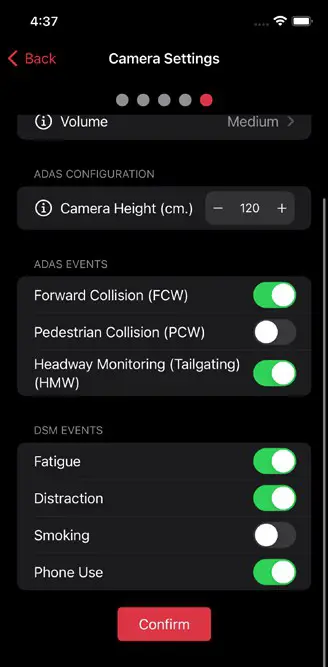 | 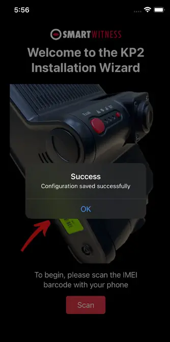 |
| 7. After you’ve made changes and activated the appropriate features, click Confirm to save your configuration. | 8. On the home screen, you’ll see a success message validating your saved configuration. |
COMPLETE YOUR INSTALLATION/SUPPORT
You’ve finished your KP2 installation and device calibration. Your KP2 is ready to go.
If you have any complications during the installation process or have any questions, please contact our support team at [email protected] or call us.
North America, South America, APAC
+1 (312) 981-8774
EMEA
+44 (0) 1483 397005
NOT AN INSTALLER?
Once you complete the training (about a 30-minute webinar), SmartWitness will provide you with login credentials for the SmartOPS portal.
To schedule training, please complete the online form here.
LED & BUZZER SPECIFICATIONS
Status/Step
| LED | SOUND | ||
| Warning | Record | Communication | |
| Startup Et Power Off | Booting Step 1 | On | Off | Off | – | |
| Booting Step 2 | On | On and Off | Off | – | ||
| Booting Step 3 | On | On | On and Off | – | ||
| Booting Finished | On | On | On | – | ||
| Power Off | Off | Fast Simultaneous On and Off | Beep No. 2 | |||
| Power Off Finished | Off | Off | Off | |||
| Record | Continuous Record | Recording | – | On | – | – |
| Event Record | Standby | – | On | – | ||
| Recording | Fast On and Off | – | – | |||
| Dual Record | Continuous Recording | – | On | – | ||
| Event Recording | – | Fast On and Off | – | – | ||
| No Record | No Recording | Off | – | |||
| Communication | 4G LTE Network Device Ready | – | – | On | – | |
| Communication | – | – | On | – | ||
| Function | SD Format | Off | Sequence On and Off | Continuously Beep No. 2 | ||
| G-Sensor Calibration | – | – | Beep No. 2 | |||
| RN Upgrade | – | Double Sequence On and Off | – | |||
| Warning | System Warning | SD Card Full | Fast On and Off | Off | – | Beep No. 3 |
| Video Loss | On | – | – | – | ||
| Error | Record Error | , SD Error No SD, Write Fail | Slow On and Off | Off | Beep No. 3 | |
| Communication Error | 4G LTE Network Device Error, SIM Error | Of f | ||||
| Data Network Connection Error | Slow On and Off | |||||
| DMS Communication Error | Slow On and Off | |||||
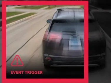
| Event Trigger | G-Sensor, Panic Button, Alarm-In | – | – | – | Beep No.1 | |
| Over Speed | – | – | – | Beep No. 4 (2 Times) | ||
| ADAS | PCW, FCW, HMW | – | – | – | Warning Beep or Voice | |
| DSM | DSW, DFW, DPUW, DDW | – | – | – | Warning Beep or Voice | |
TECHNICAL SPECIFICATIONS
| NAME Image Sensor | VALUE 2 Megapixel CMOS Sensor |
| Angle of View | Main, Road-Facing Camera (Forward-Facing): 140° (115°(H). 601V)) |
| 2nd Camera (Optional, Driver-Facing): 130° (104°(H) x 56°(V)) | |
| Wireless | LTE CAT6 (KP2-NA): 82/B4/B5/B7/B12/B13/ B14/B17/B25/B26/B41/B66/B71 |
| LTE CAT6 (KP2-GB): Bl/B2/B3/B4/B5/B7/B8/ B20/B28/B38/B40/B41 | |
| 3G (KP2-GB): B1/B2/134/B5/B8 | |
| Wi-Fi: 2.4/5GHz. 802.11 a/b/g/n/ac | |
| Bluetooth: 4.2 BLE | |
| Connectivity | 4G/LTE (CAT6) |
| Max Data Rate | UL: 50Mbps, DL: 300Mbps |
| Video Resolution | Main Camera: 1080p (1920 x 1080). 720p (1280 x 720) |
| 2nd Camera:1080p (1920 x 1080), 720p (1280 x 720) | |
| Recording Speed | 60FPS (30FPS per Channel) |
| Recording Mode | Continuous, Event, Dual Mode |
| Memory | 16GB eMMC + 2GB LPDDR3, MicroSD Card Support up to 256GB (FAT32) |
| GPS/GNSS | Internal GPS/GLONASS/BeiDou |
| G-Sensor | Internal 3-Axis G-Sensor |
| Gyro | 3 Axis (X. Y, Z), Output Rate:100Hz |
| Time | GPS Time Sync + Built-In Real-Time Clock (RTC) |
| Speaker | Audible Alerts for Events and Audio for ADAS and DSM. Natural Language or Beep Sounds (Selectable) |
| Audio | Internal Microphone |
| Serial | RS232 RX/TX |
| LED | 3 (Red, Blue, Green LED) |
| Supercapacitor | Enables Recording of Last File and Safe Shutdown |
| PC Software | MSM8953. Octa-Core ARM Cortex-A53 |
| Power Input | Input Voltage: DC 12V/24V, 1.5A |
| Delayed Power Shutdown | Supports Delayed Power Shutdown and Automated Wake-Up Feature (Selectable Intervals) |
| Power Consumption | 4W (6W With ADAS and DSM Enabled) |
| Size/Weight | 126 x 82 x 64 mm/232.4g (Including 2nd Camera, Excluding Power Cable) |
| Operational Temp. | -10°C-55°C |
| Storage Temp. | -20°C-70°C |
| Certification/ Regulatory | FCC, CE, E-Mark, UKCA, RoHS, IC, PTCRB, RCM, AT&T, Verizon and FirstNet |
| Warranty | 2-Year Standard |
![]() © 2022 SmartWitness. All Rights Reserved.
© 2022 SmartWitness. All Rights Reserved.


