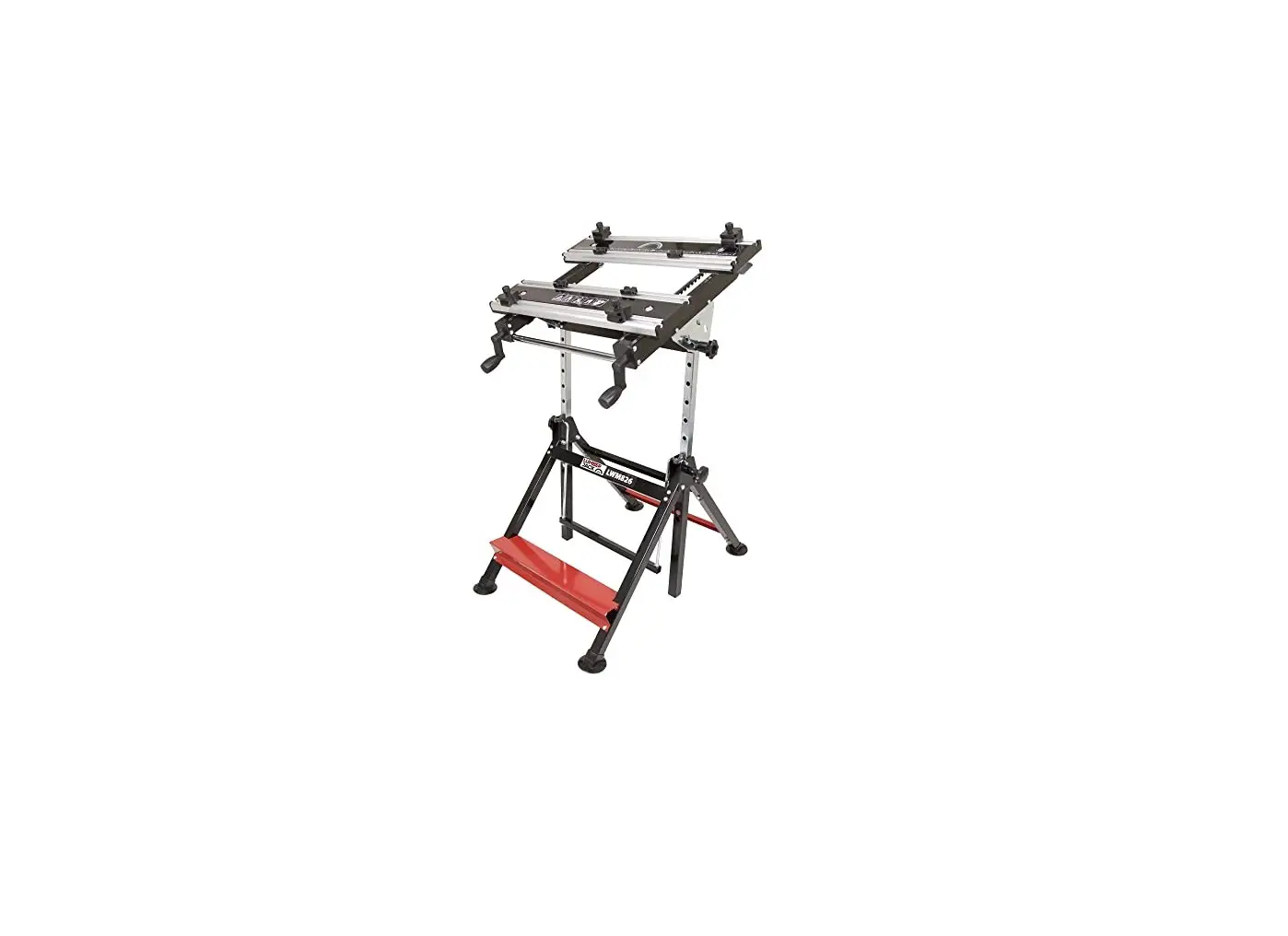
Lumberjack LWM826 Germany Professional Workbench, Sturdy Steel Frame and Aluminium Work Instruction Manual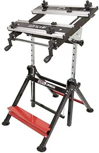
PARTS LIST
| NO | FIGURE | DESCRIPTION(MM) | QTY |
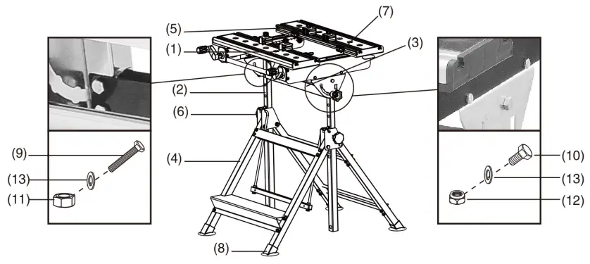
| #1 | 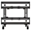 | BENCH TOP WITH SLIDING BAR | 1PC |
| #2 | 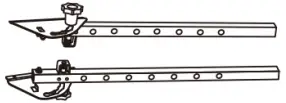 | ELEVATING ROD WITH TILT ADJUSTER | 2PCS |
| #3 | 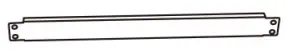 | CROSS BAR | 1PC |
| #4 | 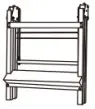 | LEG FRAME | 1PC |
| #5 |  | BIG CLAMP | 4PCS |
| #6 |  | HEIGHT FIX KNOB | 2PCS |
| #7 |  | SMALL CLAMP | 4PCS |
| #8 |  | LEG FEET | 4PCS |
| #9 | 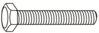 | M6X35 BOLT | 4PCS |
| #10 | 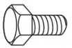 | M6X12 BOLT | 4PCS |
| #11 |  | M6 NUT | 4PCS |
| #12 |  | M6 NYLON NUT | 4PCS |
| #13 | M6 WASHER | 8PCS | |
| #14 |  | WASHER FOR HEIGHT FIX KNOB | 2PCS |
Assembly Instructions
Step 1: Attach the four leg feet (8) to the leg frame(4)
Step 2: Attach cross bar (3) to the two elevating rods (2) with M6 x 35 hex bolts (9), M6 nuts(11) and M6 washers (13). Make sure the seven pre-drilled holes on both elevating rods are facing the same way and toward the back of the workbench and the adjusting knobs are on the outside of the assembly.
Step 3: Pull the elevating swing bar backwards and insert the elevating rod assembly into the frame tubes ensuring that the latches on the swing rods fit into the holes on the elevating rods.
Step 4: Use height fix knob(6) to tighten elevating rod(2) to secure the workbench at a given height.
Step 5: Lay the bench top (1) onto the top of the elevating rod assembly. Ensure the frame of the bench top sits outside the tops of the legs. Attach using M6 x 12 bolts (10), M6 safety hex nuts (12) and M6 washers (13)
Step 6: Big clamps (5) can be inserted into the top channels. Pull the big clamp (5) up and turn it around to adjust the angle of the clamp, as required.
Step 7: Small clamps (7) can be inserted into the side channels, as required.
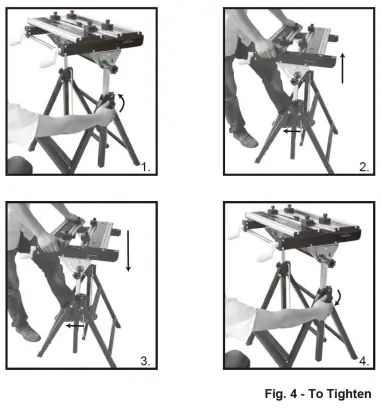
Functions
- Height Adjustment (seven levels).
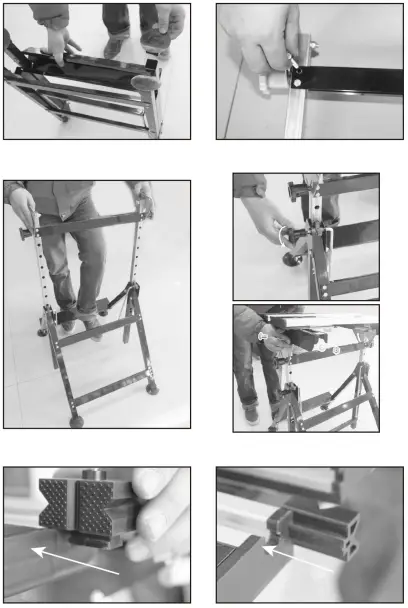
a. Turn the height adjustment knobs counter-clockwise on each leg to loosen (fig. 1).
b. Pull the elevating swing bar back with your foot to disengage the two hooks and adjust the height of the bench upwards (fig. 2) or downwards (fig. 3).
c. Use the elevating swing bar to ensure the two hooks are re-engaged into the two elevating rods’ adjustment holes.
d. Turn the height fixing knobs clockwise on each leg to tighten (fig. 4). Note: Ensure the height fixing knobs are tight before using the workbench.
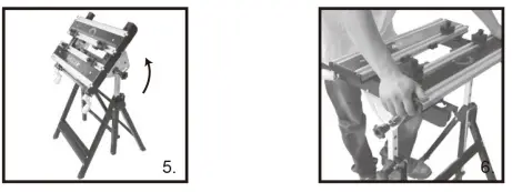
- Tilt angle adjustment (four levels).
a. For normal use, the bench top will be set horizontal, however the top can also be adjusted to 25°, 50° and 80°.
b. Ensure that the tilt adjustment knobs are completely unscrewed.
c. Push the two adjustment knobs in simultaneously and tilt the bench top until the knobs engage into the next set of preset guide holes (fig. 5).
d. Turn the tilt adjustment knobs clockwise to tighten the bench top and hold the desired position.
Note: Ensure the tilt adjustment knobs are tight before using the workbench. Use the preset guide holes only.
- Bench top adjustment
a. To adjust the bench top, pull up both levers on each sliding bar and slide forwards or backwards as desired (fig. 6).
b. Ensure that the mechanism is securely engaged in the holes in both sliding bars.