Kingfar ERGOLAB BoiSesor ExGSensor
Instructions Manual
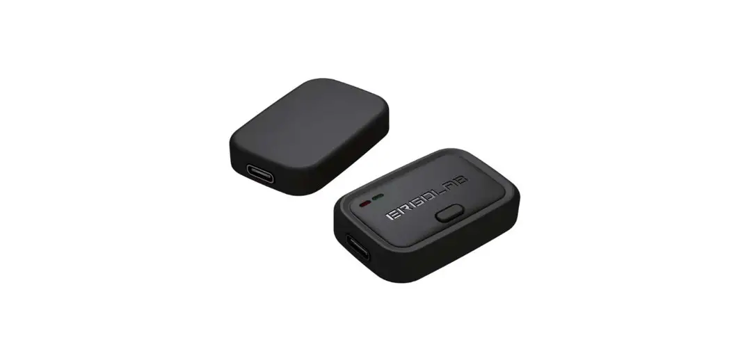
ErgoLAB wireless physiological recorder
The new generation of ErgoLAB wireless human factors recorder includes Biosensor sensor and EXGSensor sensor types. All hardware adopts modular design, built-in Type-C interface, and unified collector and different signal source acquisition lines are configured to realize synchro-nous lead of multiple systems. At the same time, the equipment built-in acceleration, gyroscope, magnetometer, in the collection of EMG, RMS, ECG, EDA, RESP, SKT, Sp02, HR, and other multidimensional physiological signals, but also can obtain high-precision human motion posture data. The product has the characteristics of intelligence, high precision, and portability, which can meet the diverse needs of laboratory research, real field research, and various simulated cabin environment research.
 BioSensor wireless human physiological recorder adopts signal self-identification technology and is equipped with a unified collector. According to research requirements, the collection line of corresponding physiological signals can be arbitrarily connected. The equipment includes PPG blood volume pulse, EDA skin electricity, RESP respiration. SKU skin temperature, FSR fingertip pressure, and other indicators, each sensor can collect multiple signal indicators.
You can complete the measurement mode of any index by adding sensors and electrode wires at any time.
EXGSensor wireless human factor sensor device adopts signal self-identification technology and is equipped with a unified EXG collector and acquisition line. According to research requirements. it can be equipped with EMG/ECG/EOG/EEG signal types, supporting patch mode, and external acquisition line mode. The sampling frequency is up to 4096Hz which can realize synchronous lead of multiple systems. At the same time. built-in acceleration, gyroscope. the magnetometer can obtain the human body’s motion posture data.
Core advantages
- Adopting multi-signal and multi-sensor fusion design, every single sensor can collect multiple data indicators at the same time.
- The equipment selects high-precision components, the system resolution can reach 16-24bit. single-channel sampling rate is the highest 4096Hz:
- One too many data transmission protocols, using Bluetooth 5.0 ultra wideband transmission, can collect multiple devices at the same time;
- All products adopt modular designs. support intelligent insertion detection signal Type, support Type-c external sensor;
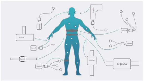
- The new sensor is designed to be portable and wearable. Including a band, buckle, bracelet, ear clip, finger, chest strap six wearing mode;
- All sensors are uniformly calibrated for NTP network time before delivery to ensure time synchronization of all data collection and eliminate clock differences between different sensors and different computers. At the same time, the sensor and the system will automatically real-time synchronous calibration;
- New appearance design. Material and process upgrade to ensure product comfort and beauty;
- Catalog,. APR PAD, PC multi-terminal device collection;
- With marking function. It can be controlled by the subjects freely and mark the time at a certain test stage to help better data analysis
Parts list
BioSensor Parts List
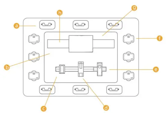
| a.Bind card bucklex6 |
| b. BioSensor instructional |
| c. Dongles l |
| d. Receive donglexl |
| e. Installation packages1 |
| f. Bio5Sens0rx6 |
| g. Chargerx1, Charging cable x6 |
| h. Lead wirex6 |
![]()
IO 1 _________ S/N 20212SBP000X _______ PPG
BIO 3 ________S/N 20212SBR000X ________ RESP
BIO 5 ________ S/N 20212SBS000X ________ FSR
EXG 1 ________ S/N 20212SEC000X _______ ECG
BIO 2 _________ S/N 20212SBE000X ______ EDA
BIO 4 _________ S/N 20212SBS000X ______ SKT
EXG 2 ________ S/N 20212SEM000X ______ EMG
Manner of wearing
- Exg-patch acquisition mode: three silver/silver chloride electrodes are embedded in the sensor, which only needs to be fixed on the skin surface of human muscles with double-sided adhesive to remove the influence of cables, especially suitable for fine research of small muscle groups; New appearance design. Material and process upgrade to ensure product comfort and beauty;
- 610, EXG-Type-C external sensor acquisition: the system can automatically insert detection, customize the electrode measurement position, support the long-distance test of large muscle groups, better adapt to the requirements of different muscle group position data acquisition.

BioSensor Specific operation
BioSensor process includes four main steps: installing the sensor, wearing the sensor, starting the sensor, and connecting software for data collection.
Such as:
Wear way
Installation
The sensor is fixed in the card slot and the card slot is connected with the strap by means of penetration
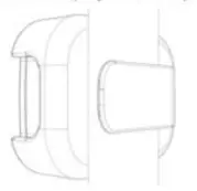
The sensor is fixed in the card slot and the card slot and the strap are connected by a clamp
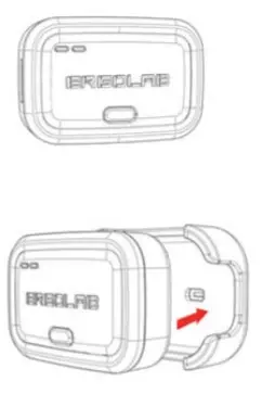
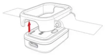
Wear (wireless wear)
 Push the sensor into the card slot, and the card slot is directly connected with the strap
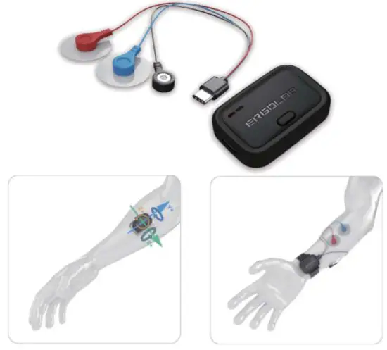
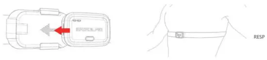
Wear (wired wear)
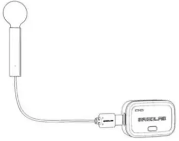
Connect the sensor to the lead wire
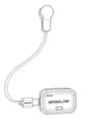
The heart rate ear clip is inserted into the sensor, the sensor is fixed in the card slot, and the card slot is connected with the strap by means of insertion
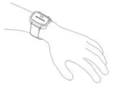
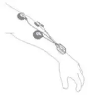
Worn in the appropriate position of the body
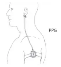 Sensors are worn on the upper arm and heart rate ear clips are clipped to the ears
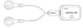 | 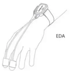 |
| Insert the lead wire with electrode buckle into the sensor, and the sensor is fixed in the clamp. The clamp is connected with the strap. | The sensor is worn on the wrist and the electrode buckle is fixed on the finger |
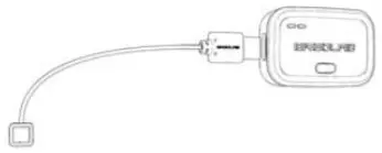 | 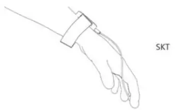 |
| Insert the lead wire with electrode buckle into the sensor, and the sensor is fixed in the clamp. The clamp is connected with the strap. | The sensor is worn on the wrist. Attach the collecting end to the finger |
 | 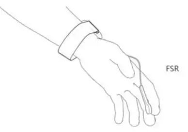 |
| Insert the lead wire with electrode buckle into the sensor, and the sensor is fixed in the clamp. The clamp is connected with the strap. | The sensor is worn on the wrist. Press or pinch the sensor |
Start
Pegs the switch and the equipment starts
Connection
Software installation
BioSensor Specification param-
| Coiled | Gathering indicators | EDA, PPG, HR, SKT, SP02, RESP, ACC, GYRO, COMP, Analog, FSR |
| Acquisition methods | Patch collection or external sensor collection | |
| System sampling rate | 2048Hz | |
| System resolution | 16bit | |
| Acquisition software | Android APP or Windows cross-platform software | |
| Type-C | Function | Data acquisition Charging input Insertion detection |
| External input | PPG, EDA, RESP, SKT, SP02, Analog, FSR | |
| Communication | Communication methods | Radiofrequency 2.4GHz |
| Transmission rate | 2Mbps | |
| CMRR | 115d8 | |
| Single signal parameter | ||
| PPG | Collection scope | 0-240bpm |
| Precision | 1% | |
| Sampling rate | 64Hz-128Hz | |
| EDA | Collection scope | 0-300 |
| Precision | 0 001uS | |
| Sampling rate | 64Hz-128Hz | |
| RESP | Collection scope | 0 – 14Orpm |
| Precision | 1rpm | |
| Sampling rate | 64Hz-128Hz | |
| SKT | Collection scope | 20-60*C |
| Precision | 0 OM | |
| Sampling rate | 64Hz-128Hz | |
| FSR | Collection scope | 20g-6KG |
| Precision | 0.01Kg/cm2 | |
| Sampling rate | 64Hz-128Hz | |
| Analog | Collection scope | 0-12V |
| Sampling rate | 64Hz-128Hz | |
BioSensor Specification parameter
| Mechatronics specification | ||
| Sensor specifications | 45*30*13mm 172g | |
| Common charging interface | USB Type-C | |
| Battery life | 15h | |
| Communication distance | 10m | |
| Operating environment | Working temperature -20°C-509C | Working temperature 10%-90%RH |
| Storage temperature -40°C-50°C | Storage temperature 5%-90%RH | |
BIO Sensor Acceleration and magnetometer axis orientation. As shown in the figure below (Take Type-c to the left as the front):
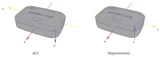
EXG Sensor Acceleration and magnetometer axis orientation. As shown in the figure below (Take Tvoe-c to the left as the front:
EXGSensor Specific operation
EXG Sensor process consists of four main steps: installing the Sensor, wearing the Sensor, starting the Sensor, and connecting the software for data collection. As shown below:
Wear way (Wireless wear)
Installation
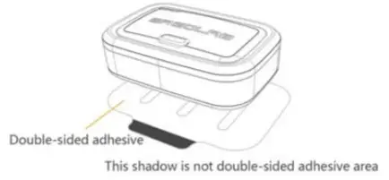 | 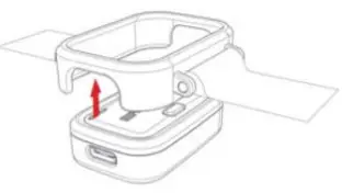 |
| Adhesive method: stick one side of the built-in double-sided adhesive on the back of the product. The other side is placed at the test skin | Binding method: the sensor is fixed on the binding buckle from the bottom |
Fixed
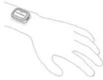 |  |
| Paste on the test site | Hang the bandage on the test site. Adjust bayonet position and fasten |
Start
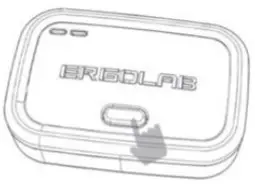 Press the switch and the equipment starts
Connection
 Software installation
Another way (Cable wear)
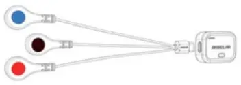 |  |
| Plug the lead wire into the charging port on the left side of the sensor | Connect the collecting end with the position |
| Collect | Gathering indicators | EMG, ECG, HR, ACC, GYRO, COMP, RMS | |||
| Acquisition methods | Patch collection. External sensor collection | ||||
| System sampling rate | 4096Hz | ||||
| System resolution | 16bit | ||||
| Acquisition software | Android APP or Windows cross-platform software | ||||
| Type-C | Function | Data acquisition Charging input Insertion detection | |||
| External input | EMG, ECG | ||||
| Communication | Communication methods | 2.4GHz | |||
| Transmission rate | 2Mbps | ||||
| Magnification | Adjust1S00, 3000, 6000 | ||||
| CMRR | 86dB | ||||
| Single signal parameter | |||||
| EMG | Collection scope | -6000pV-6000pV | |||
| Precision | 0183 pV | ||||
| Sampling rate | 256-4096Hz | ||||
| ECG | Collection scope | -6000pV-6000pV | |||
| Precision | 0.183 pV | ||||
| Sampling rate | 256-4096Hz | ||||
| ACC | Precision | 0.06mg | |||
| Sampling rate | 64Hz-128Hz | ||||
| GYRO | Precision | 0.0077s | |||
| Sampling rate | 64Hz-128Hz | ||||
| COMP | Precision | 0.941T | |||
| Sampling rate | 128Hz | ||||
| Mechatronics specification | |||||
| Sensor specifications | 451’30’13mm 17.2g | ||||
| Common charging interface | USB Type-C | ||||
| Battery life | 1Sh | ||||
| Communication distance | 10m | ||||
| environment | Working temperature -20°C-SO°C | Working temperature 10%-90%RH | |||
| Operating | Storage temperature -40°C-50°C | Storage temperature S%-90%RH | |||
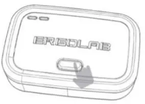
Indicator status
The following describes the status of sensor LED lights in use and the corresponding meaning:
Battery indicator light:
![]()
When charging, the battery light flashes at low frequency and the color is determined by the electric quantity. After charging, the green light is steady on, and the Bluetooth light is off. After startup, the battery light will be on every Ss and off for the rest of the time:
| Bluetooth light color | Bluetooth light status | Meaning |
| Put out | When the device is in charge mode, the Bluetooth light is off | |
| Normally on | (Wired) The device is disconnected after being turned on | |
| High-frequency blinking | (Bluetooth) After the device is turned on, it is in a broadcast state | |
| Normally on | It is connected to the receiving end | |
| Low-frequency blinking | After the software is connected, data is reported | |
| Low-frequency blinking | The collection end is abnormal | |
| Power off after steady on | When the power is less than 3% |
PS:
- Press on key equipment to start
- Long press the key device to shut down
- After startup, press the open key to mark the event
- Bluetooth indicator on the left and battery indicator on the right
- If no data is transmitted after the device is started, the indicator is in blue
- After the device is started and data is being transferred, the indicator is green
- When the Bluetooth indicator turns orange and flashes at low frequency, it indicates that data collection is abnormal. Check whether the electrodes are properly connected
- If the device is not connected 3 minutes after startup, it will below. power mode.
At this time, press the on key again to turn on
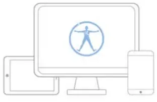
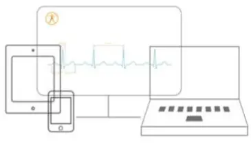
Data collection
ErgoLAB synchronization test cloud platform acquisition system
Ergot/NB is independently developed by Ma Technology, which can be applied to scientific research, personnel status identification, product design evaluation, intelligent measurement of the human-information system. Professional and efficient cloud architecture comprehensive platform in the direction of rating. It includes subjective and objective experimental design, multi-equipment data acquisition, and data analysis statistical report in one and builds a complete test process system.
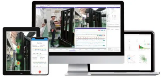
ErgoLAB Datalogger APP portable acquisition system.
Datalogger APP enables real-time collection of all physiological data without any cables or computers, making it the best choice for outdoor research. At the same time as physiological data collection, temporal and spatial trajectory data can be collected synchronously, and then imported into the ErgoLAB system for physiological signal analysis and temporal and spatial analysis, supporting synchronous analysis and comprehensive statistics with other multimodal data.

This device complies with part 15 of the FCC Rules. Operation is subject to the following two conditions: (1) this device may not cause harmful interference, and (2) this device must accept any interference received, including interference that may cause undesired operation.
Any changes or modifications not expressly approved by the party responsible for compliance could void the user’s authority to operate the equipment.
NOTE: This equipment has been tested and found to comply with the limits for a Class B digital device, pursuant to Part 15 of the FCC Rules. These limits are designed to provide reasonable protection against harmful interference in a residential installation. This equipment generates, uses, and can radiate radio frequency energy and, if not installed and used in accordance with the instructions, may cause harmful interference to radio communications. However, there is no guarantee that interference will not occur in a particular installation. If this equipment does cause harmful interference to radio or television reception, which can be determined by turning the equipment off and on, the user is encouraged to try to correct the interference by one or more of the following measures:
- Reorient or relocate the receiving antenna.
- Increase the separation between the equipment and receiver.
- Connect the equipment into an outlet on a circuit different from that to which the receiver is connected.
- Consult the dealer or an experienced radio/TV technician for help.
The device has been evaluated to meet general RF exposure requirements. The device can be used in portable exposure conditions without restriction
FCC ID: ADKA-ERGOLAB-FNIRS


