![]()
6el 50/70MHz Dual Band Yagi
High Performance hybrid log
Model: 6-duo-5070
Z08564-0030
Rev. V1.4 – 19/02/2020
Copyright InnovAntennas 2020
Revision 1.4
InnovAntennas
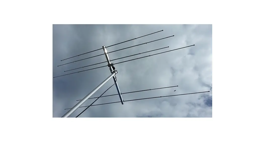
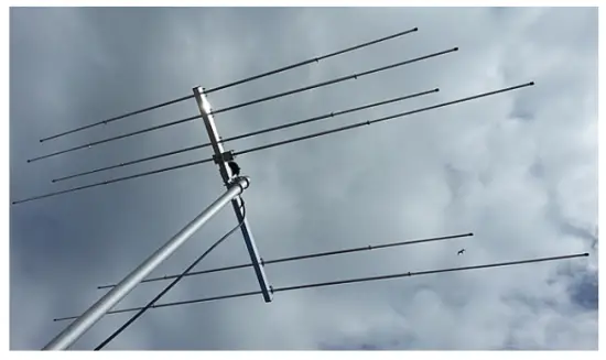
50/70MHz 6el 50 Ohm Dual Band Yagi
(NOT TO SCALE)
Testing the antenna
Please read the rest of the manual before testing and ensure a 1:1 balun or common mode choke is installed at the feed point. For effective ‘on ground’ testing your antenna should be at least one 1/4 wave or one boom length (whichever is the greatest length) above ground. It should also be pointed to a clear horizon with no building, trees, or other objects in its view.
If a clear view is not possible, remove the top 50mm U-bolt from the boom to mast plate and allow the antenna to angle upwards in order the reflector is lower to ground than the director(s) and the antenna is pointing to clear sky. This will ensure that any final tuning you do at ground level is least likely to alter once the antenna is installed into
its final position.
Help and assistance @ [email protected]
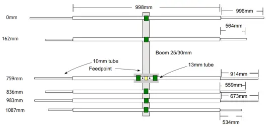
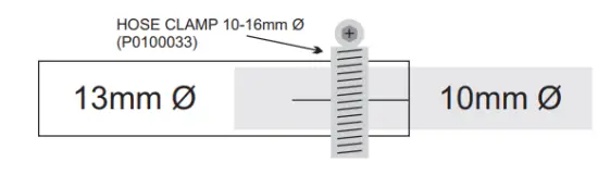
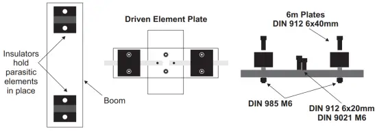
The driven element loop ends are fixed in place with a hose clamp 8-16mm (P0100022) at each corner of the 13 to 10mm diameter tubes.
7-11mm (P0100031) hose clamps hold the loop end in place and allow for adjustment (SWR).
Measurements on the drawing on page 2 are exposed lengths for each tube. The element sections’ total length will be longer than this to allow for overlap. For antennas that have tapered elements, it is advisable to insert the center section into the white insulator clamp and tighten both to the boom before inserting the tips, measuring and finalizing each element’s respective length.
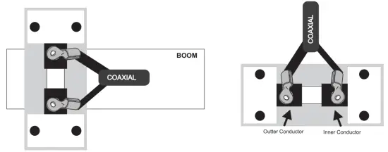
The driven element section of the loop (closest to the reflector) has a small plate with two white insulators, one on either side of the feed point. 2 M6 bolts DIN 912 6 x 20mm hold this plate in place. More details of the feed point arrangement are shown on page 6.
It is important NOT to over-tighten the insulator blocks. They need to be tight enough that neither they nor the element moves. They should not be tightened down further, this may reduce the life length of the clamp.
Grease or oil all stainless steel parts before assembly to ensure reliable fitment and long-term survivability of the antenna and its components.
InnovAntennas ConductAseal and RubbAseal are recommended when installing and are available via the InnovAntennas website.
www.innovAntennas.com
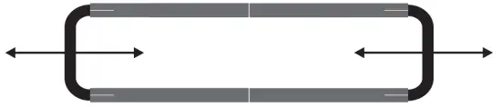
Adjusting SWR
Once you have built your antenna and it is in position on your mast or test mast, you may find you need to make some small adjustments to the loop in order to get the best SWR. Move the loop ends in and out a few mm at a time until the best result is seen. At this point, the loop hose clamps can be fully tightened.
Important notes on tuning
If the antenna is too close to the ground when tuning, you may find the SWR alters once installed in its final position. In order to elevate this, you should ensure that in the test position the Yagi is at least one ¼ wavelength or one boom length (whichever is the greater distance) above ground. Additionally, the antenna should be pointed to a clear
horizon with no trees or buildings close by. If this is not something you can achieve, then remove one of the U-bolts from the boom to mast plate in order for the antenna can point slightly upward to clear sky. An angle of at least 20 degrees will give the same readings as would be seen if the antenna was installed several wavelengths above ground.
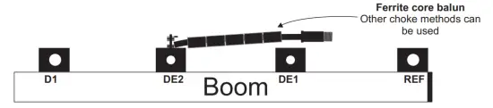
Balun – needed or not?
The LFA Yagi is a balanced antenna. Coax cable is an unbalanced feed line. If a balanced antenna is fed with an unbalanced feeder, the coax can radiate as well as the antenna and this can have disastrous consequences on the performance of a Yagi that might not otherwise be seen on antennas such as verticals and dipoles. Therefore, it is important to install a BALanced to Unbalanced transformer (1:1 balun) or choke at the feed point.
A 1:1 balun is one that connects 50Ohm coax cable to a 50Ohm antenna and prevents these common mode currents from radiating back long the coax line. While it is possible to make a very simple choke from a coil of coax at the feed point of the antenna, any such arrangement should be confirmed at working with an antenna analyzer. Often, good quality coax has a sleeve thickness too wide to provide enough capacitance between the turns of any coax coils to produce the desired choking. More information can be found here on baluns and configuration:
http://www.innovantennas.com/why-do-i-need-one.html
For any help and support, please email us at [email protected]
PACKING LIST
BAG #1
BAG #2
LARGER BOXED ITEMS
| PARTY | PART IMAGE | DESCRIPTION | SIZES | QUANTITY |
| EA013018 |  | Boom to Mast plate | 100 x 100 x 6mm | 1 |
| A-0163 |  | U-BOLT | M8 x 50mm | 2 |
| 23035.50 |  | SADDLE CLAMP | 50mm | 2 |
| S127-98 |  | DIN 127 WASHER | M8 | 4 |
| S934-98 |  | DIN 934 NUT | M8 | 4 |
| P0500030 |  | Square 30mm Clamp | M6 x 30mm | 2 |
| S9021-96 |  | DIN 9021 | M6 | 4 |
| S934-96 | | DIN 934 | M6 | 4 |
| EA0105A6 |  | DE1 Elements plates | 100x50x4mm | 1 |
| S912-9620 | Allen DIN 912 bolt | 20x6mm | 2 | |
| S9021-96 | | DIN 9021 | M6 | 2 |
| EAHYP013 |  | 13mm 0 Insulator blocks | Element insulators/holders | 7 |
| 3912-9640 | Allen DIN 912 bolt | 40x6mm | 14 | |
| S985-906 | | DIN 985 NUT | M6 | 4 |
| P0100022 |  | Hose clamp | 8-12mm | 12 |
| A-A | Boom Section | 1275mm x 30mm | 1 | |
| The middle part of Elements | 998mm x 13mm Ø | 5 | ||
 | The middle part of DE1 | 998mm x 13mm Ø | 1 | |
| DE1 | DE1 DRIVEN TIP | 1014mm x 10mm Ø | 2 | |
| REF-SO | REFLECTOR | 1096mm x 10mm Ø | 2 | |
| Dl-50 | DIRECTOR 1 | 773mm x 10mm Ø | 2 | |
| Dl-70 | DIRECTOR 2 | 664mm x 10mm Ø | 2 | |
| D2-70 | DIRECTOR 2 | 659mm x 10mm Ø | 2 | |
| D3-70 | DIRECTOR 2 | 634mm x 10mm Ø | 2 |
Boom Length: 1.1m
Feed system: 1 feedline with 1:1 balun
Wind Survival: 115 mph
Direct 50-ohm feed
Copyright, InnovAntennas Limited 2018
www.innovantennas.com


