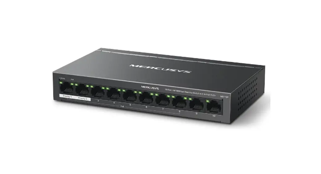
MS110P PoE Desktop Switch
Installation GuideQuick Installation Guide
PoE Switch
MS110P PoE Desktop Switch
LED Explanation
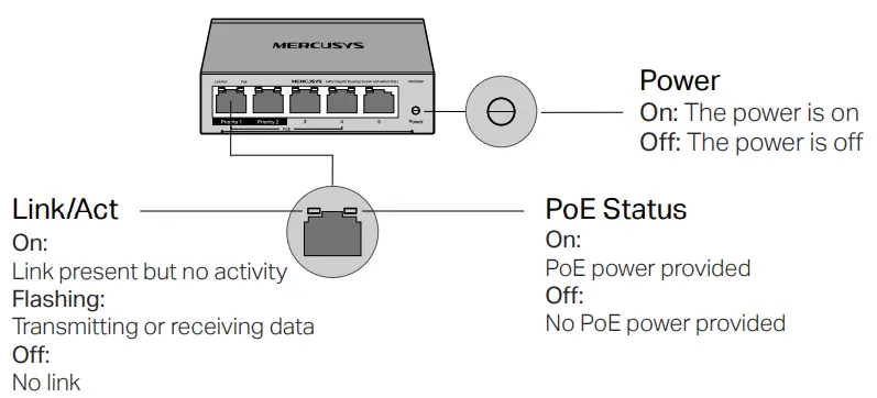
Note: For MS108GP, the Power LED is on the top right of port 8.
Switch Explanation
Extend (for MS105GP/MS108GP/MS110P)
Off: Ports run at 1000/100/10 Mbps (100/10 Mbps for MS110P) and support PoE power supply up to 100m away.
On: Ports run at 10 Mbps and support PoE power supply up to 250m away.
Recovery (For MS110P)
Off: The PoE Auto Recovery function is disabled.
On: The switch will constantly detect the working status of a PoE powered device (PD).
When the switch finds that the PD works abnormally, the switch will reboot it.
Isolation (For MS105GP/MS108GP/MS110P)
Off: Ports can transmit data with each other.
On: Specific ports cannot transmit data with other downlink ports. They can transmit data only with the uplink ports (port 5 of MS105GP/port 8 of MS108GP/ports 9-10 of MS110P).
Connection
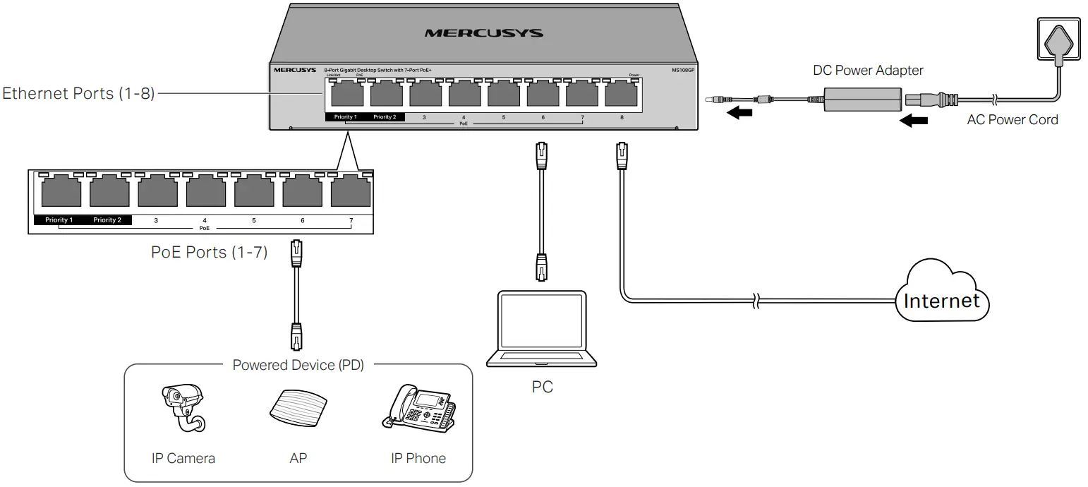
Notes:
- PoE ports can also connect to non-PoE devices, but only transmit data.
- Non-PoE ports (port 5 of MS105GP/port 8 of MS108GP/ports 9-10 of MS110P) are recommended to connect to uplink devices like routers.
- Ports 1-2 have higher priority than other ports in transmitting data if network congestion occurs. It is recommended to connect key network devices (network cameras, APs, etc.) to ports 1-2.
Specifications
General Specifications
| Standard | IEEE 802.3i, IEEE 802.3u, IEEE 802.3ab (for MS105GP and MS108GP), IEEE 802.3x |
| Protocol | CSMA/CD. 802.3af/at PD supported |
| Interface | MS105GP: 5 1000 Mbps RJ45 Ports Auto-Negotiation/Auto MDI/MDIX PoE Ports: Port 1–4 MS108GP: 8 1000 Mbps RJ45 Ports Auto-Negotiation/Auto MDI/MDIX PoE Ports: Port 1–7 MS110P: 10 10/100 Mbps RJ45 Ports Auto-Negotiation/Auto MDI/MDIX PoE Ports: Port 1–8 |
| Network Media (Cable | 10BASE-T:2-pair UTP/STP (≤100m) of Cat. 3 or above 100BASE-TX:2-pair UTP/STP (≤100m) of Cat. 5 or above 1000BASE-T:4-pair UTP/STP (≤100m) of Cat. 5e or above |
| Switching Capacity | MS105GP: 10 Gbps MS108GP: 16 Gbps MS110P: 2 Gbps |
| MAC Address Table | 2K 8K (only for MS108GP) |
| Forwarding Method | Store-and-Forward |
| MAC Address Learning | Automatically learning, automatically aging |
| Power Supply | External Power Adapter Input: 100-240 VAC, 50/60 Hz Output: 53.5 VDC/1.31 A |
| PoE Budget | 65 W (up to 30 W for each PoE port) |
Environmental and Physical SpecificationsCertification CE, RoHS Operating Temperature 0˚C to 40˚C (32˚F to 104˚F) Storage Temperature -40˚C to 70˚C (-40˚F to 158˚F) Operating Humidity 10% to 90% non-condensing Storage Humidity 5% to 90% non-condensing
Frequently Asked Questions (FAQ)

– The Power LED should be lit when the power system is working normally. If the Power LED is not lit, please check as follows:
– A1: Make sure the AC power cord/power adapter is connected the switch with power source properly.
– A2: Make sure the voltage of the power supply meets the requirements of the input voltage of the switch.
– A3: Make sure the power source is on.
– It is recommended that you check the following items:
– A1: Make sure that the cable connectors are firmly plugged into the switch and the device.
– A2: Make sure the connected device is turned on and working well.
– A3: The cable must be less than 100 meters long (328 feet). If Extend Mode is enabled, it should be less than 250 meters (820 feet).
– When the total power consumption of connected PoE devices exceeds the maximum, the PoE port with a smaller port number has a higher priority. The system will cut off
power to the ports with larger port numbers to ensure supplying to other ports.
– Take MS108GP as an example. If port 1, 2 and 4 are consuming 18 W respectively, and an additional PoE device with 15 W is inserted to port 3, the system will cut off the
power of port 4 to compensate for the overload.
– A1: Before upgrading a connected PoE powered device (PD), disable PoE Auto Recovery to avoid the PD’s damage.
– A2: When a PD does not send data packets to the switch for a long period in certain scenarios (e.g. an IPC in sleep mode), disable PoE Auto Recovery to avoid the PD repeatedly rebooting.
EU declaration of conformity
Mercury’s hereby declares that the device is in compliance with the essential requirements and other relevant provisions of directives 2014/30/EU, 2014/35/EU, 2009/125/EC, 2011/65/EU and (EU)2015/863.
The original EU declaration of conformity may be found at https://www.mercusys.com/en/ce/
UK declaration of conformity
Mercury’s hereby declares that the device is in compliance with the essential requirements and other relevant provisions of the Electromagnetic Compatibility Regulations 2016 and Electrical Equipment (Safety) Regulations 2016.
The original UK declaration of conformity may be found at https://www.mercusys.com/support/ukca/
Safety Information
Keep the device away from water, fire, humidity or hot environments.
Do not attempt to disassemble, repair, or modify the device. If you need service, please contact us.
Place the device with its bottom surface downward.
Do not use damaged charger or USB cable to charge the device.
Do not use any other chargers than those recommended.
Adapter shall be installed near the equipment and shall be easily accessible.
The plug on the power supply cord is used as the disconnect device, the socket-outlet shall be easily accessible.
![]() CE Mark Warning
CE Mark Warning
This is a class A product. In a domestic environment, this product may cause radio interference, in which case the user may be required to take adequate measures.
The POE output cannot be used to charge lithium batteries or devices with lithium batteries.
| Unit | Restricted substances and their chemical symbols | |||||
| Lead (Pb) | Mercury (Hg) | Cadmium (Cd) | Hexavalent chromium (Cr+6 | Polybrominated biphenyls (PBB) | Polybrominated diphenyl ethers (PBDE) | |
| PCB | ○ | ○ | ○ | |||
| shell | ○ | ○ | ○ | |||
| Power Supplied | – | ○ | ○ | ○ | ○ | ○ |
| Others and accessories | – | ○ | ○ | ○ | ○ | ○ |
Note 1:“Exceeding 0.1 wt %”and“exceeding 0.01 wt %”indicate that the percentage content of the restricted substance exceeds the reference percentage value of presence condition. |
| For indoor use only | |
| Direct current | |
| Alternating current | |
| RECYCLING This product bears the selective sorting symbol for Waste electrical and electronic equipment (WEEE). This means that this product must be handled pursuant to European directive 2012/19/EU in order to be recycled or dismantled to minimize its impact on the environment. User has the choice to give his product to a competent recycling organization or to the retailer when he buys a new electrical or electronic equipment. | |
| Energy efficiency marking (level VI) | |
| Polarity of d.c. power connector | |
| Class II equipment | |
| Caution | |
| Operator’s manual |
Wall Mounting SpecificationsModel Screw Standard of ANSI B1.1 Minimum Length of Screw Screw-Head-to-Wall Minimum Distance Wall-Mounting-Holes Distance MS105GP 4#, (5#), 6#, 8# 7mm 1.5mm 39mm MS106LP 4#, (5#), 6#, 8# 7mm 1.5mm 39mm MS108GP 4#, (5#), 6# 7mm 1.5mm 105mm MS110P 4#, (5#), 6# 7mm 1.5mm 105mm
![]() For technical support, replacement services, user guides, and other
For technical support, replacement services, user guides, and other
information, please visit https://www.mercusys.com/support/.
© 2023 MERCUSYS 7107500251 REV1.0.0


