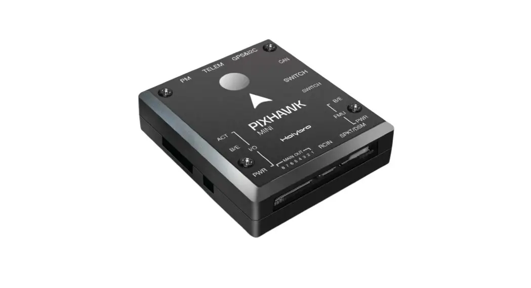
![]() PIXHAWK MINI
PIXHAWK MINI
QUICK START GUIDE v1.0
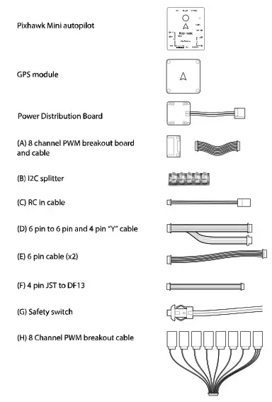
IN THE BOX
SPECIFICATIONS
Features:
- Built in Buzzer
- 8 PWM/servo outputs
- Double redundant power supply if powered by USB and PM
- Onboard safety switch and external safety switch
- Micro SD card for high rate logging over extended periods of time
Voltage Ratings:
- Power module output: 4.1~5.5V
- Max input voltage: 45V (10S LiPo)
- Max current sensing: 90A
- USB Power Input: 4.1`5.5V
- Servo Rail Input: 5~10V
Dimensions: 38x43x12mm
Weight: 15.8g
Interface :
- 1 x UART Serial Port
- Spektrum DSM/DSM2/DSM-X® Satellite Compatible
- Futaba S BUS® Compatible
- PPM Sum Signal Input I2C,CAN,ADC,Internal Micro USB Port
Sensors
- Accel/Gyro/Mag: MPU9250
- Accel/Gyro: ICM20608
- Barometer: MS5611
GPS Module:
- GNSS receiver: ublox Neo-M8N; compass QMC5883
- Weight : 22.4g
- Dimensions: 37x37x12mm
GETTING STARTED
With the help of PX4 firmware, Pixhawk mini turns any RC plane, copter, or rover into a full-featured personal drone. Once you have a fully assembled vehicle, follow this guide to install Pixhawk mini.
MOUNT
Use the provided foam pads to mount Pixhawk mini as close as possible to your vehicle’s center of gravity. Make sure to orient the board with the arrow pointing forward.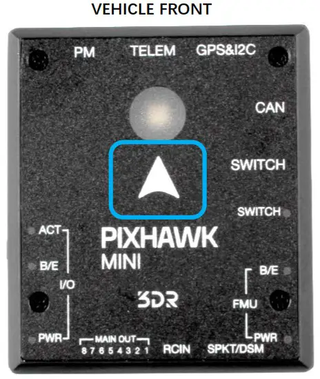
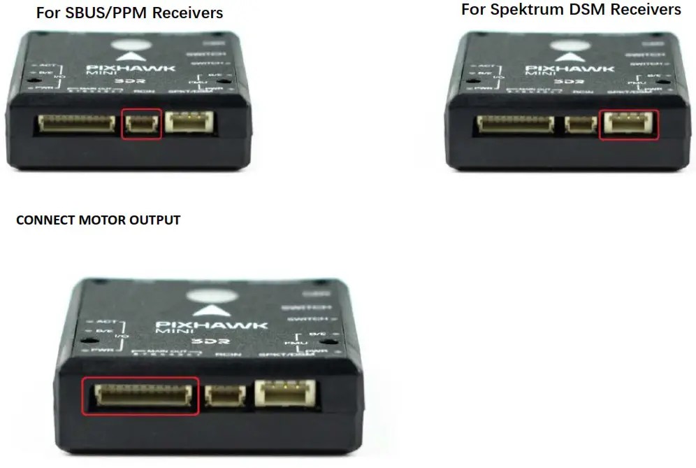
CONNECT
CONNECT RADIO CONTROL
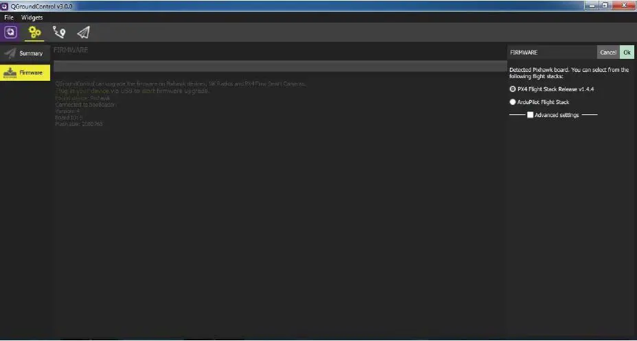
INSTALL QgroundControl
PX4 firmware is the brains of your autopilot and must be installed before using Pixhawk mini. To load firmware onto the Pixhawk mini, install QGroundControl on your computer. QGroundControl is cross platform and available on Windows, OS X, and Linux. Application available for free download from http://qgroundcontrol.com/

LOAD FIRMWARE
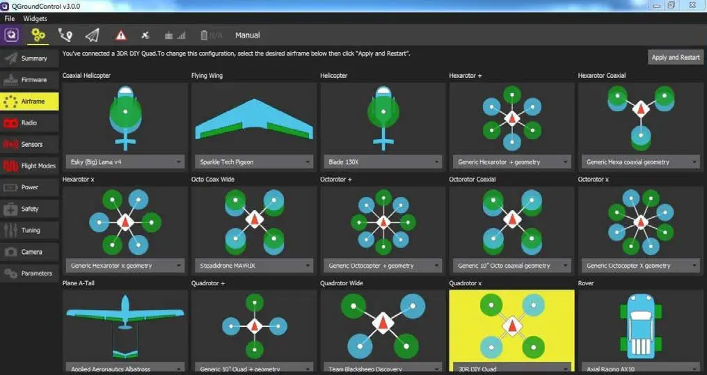
AIRFRAME
Select the specific airframe from the dropdown within the group which best matches your vehicle.
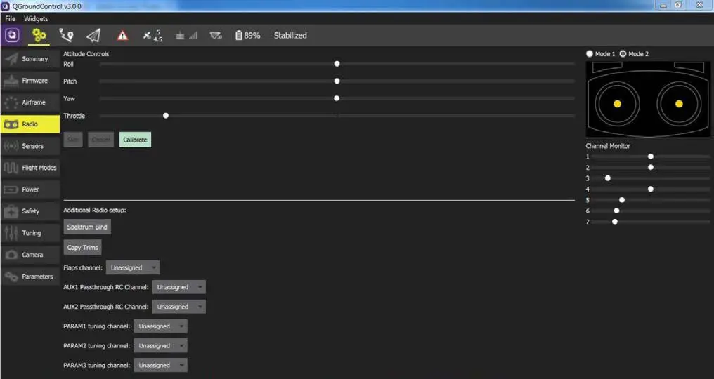
RADIO
Radio Setup is used to map your main control sticks to channels and set min/max values for these.
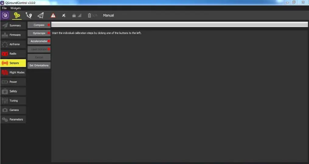
SENSORS
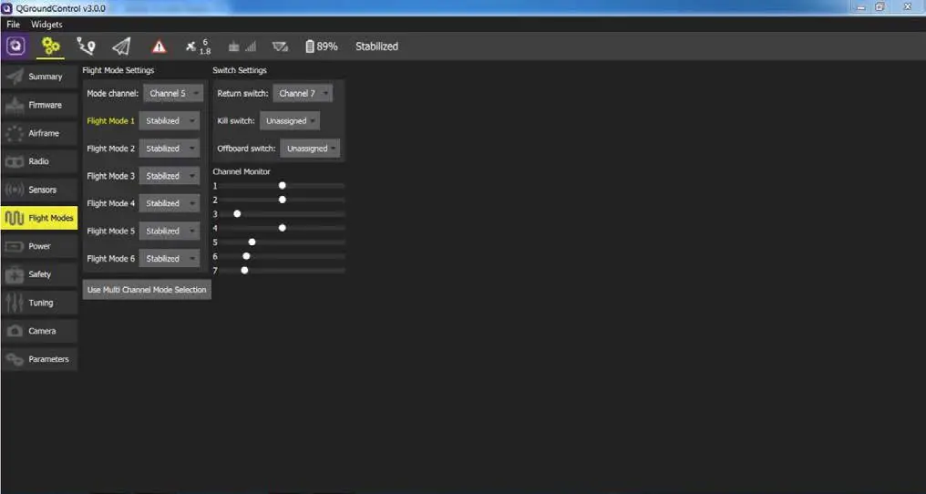
FLIGHT MODES
Here you can set up your designated Flight Modes.
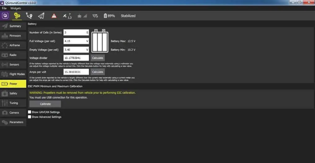
POWER
Here you can set the specifics of your battery and the power sensor that will be used.
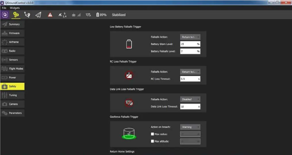
SAFETY
The Safety Setup page allows you to configure various failsafe settings as well as return home details.
OPTIONAL ACCESSORIES
Digital Airspeed sensor + Pitot tube (MS525DO) Standard Telemetry (433MHz and 915MHz)
PIN OUTS
| POWER INPUT PORT | ||
| 1(red) | SCL | +3.3V |
| 2(blk) | SDA | +3.3V |
| 3(blk) | VCC | +5V |
| 4(blk) | TX3 | +3.3V |
| 5(blk) | RX3 | +3.3V |
| 6(blk) | GND | GND |
| CHANNEL PIN OUTS | |||
| PIN | Multirotos | 4 Channel Planes | Rovers |
| Pin 1 | motor 1 | Aileron | – |
| Pin 2 | motor 2 | Elevator | – |
| Pin 3 | motor 3 | Throttle | Throttle |
| Pin 4 | motor 4 | Rudder | Steering |
| Pin 5 | motor 5 | – | – |
| Pin 6 | motor 6 | – | – |
| Pin 7 | motor 7 | – | – |
| Pin 8 | motor 8 | – | – |
| TELE M PORT | ||
| 1(red) | VCC | +5V |
| 2(blk) | TX1(OUT) | +3.3V |
| 3(blk) | RX1(IN) | +3.3V |
| 4(blk) | GND | GND |
| GPS & I2C PORT | ||
| 1(red) | SCL | +3.3V |
| 2(blk) | SDA | +3.3V |
| 3(blk) | VCC | +5V |
| 4(blk) | TX3 | +3.3V |
| 5(blk) | RX3 | +3.3V |
| 6(blk) | GND | GND |
| CAN PORT | ||
| 1(red) | VCC | +5V |
| 2(blk) | CAN-H | +3.3V |
| 3(blk) | CAN-L | +3.3V |
| 4(blk) | GND | GND |
| SAFETY SWITCH PORT | ||
| 1(red) | VCC | +5V |
| 2(b1k) | 10_LED_SAFETY | GND |
| 3(blk) | SAFETY | GND |
| RC IN | |
| 1(yellow) | SBUS/PPM |
| 2(red) | +5v |
| 3(blk) | GND |
For plances with configurations other than 4 channels, see px4.io for more information.
ADDITIONAL INFORMATION
Be sure to visit http://px4.io/ for further information including tutorials, configurations, and community support.


