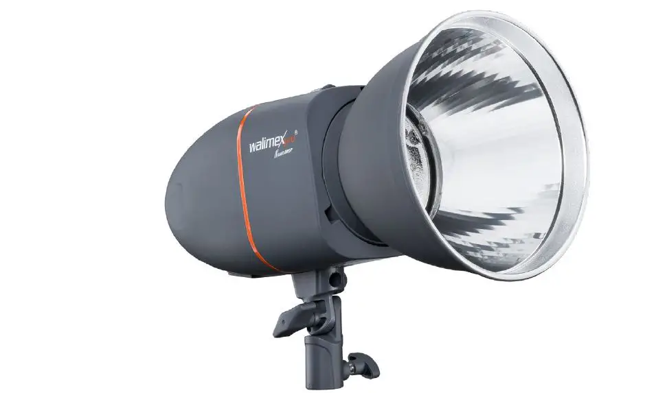
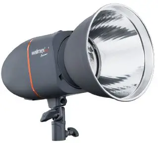
walimex pro 19546 Studio Flash
Markings on the device
CE This symbol indicates, that your device meets the safety requirements of all applicable EU-directives. Waste disposal and protection of the environment Electric and electronic appliances as well as batteries must not be disposed of together with domestic waste user is legally obliged to return electric and electronic appliances as well as batteries to specially set up public collecting points or the sales outlet once they have reached the end of their service life. Details are The regulated by national law. The symbol on the product, the instructions for use or the packaging refers to these provisions. The recycling, the material-sensitive recycling or any other form of recycling of waste equipment/ batteries is an important contribution to the protection of our environment.
Identifications in these instructions for use
Identification Draws your attention to the dealing with and the efect of safety information.
WARNING
Draws you attention to a dangerous situ- ation, which can result in severe or even fatal injury, if not avoided.
CAUTION
Indicates a hazardous situation, which, if not avoided, may result in minor or moderateinjury.
NOTE
Draws your attention to possible material damage and other important intormation in connection with your equipment.
Important safety information
WARNING
Risk of retina damage
The flash light could damage your retina up to the loss of vision, if your flash is trigged in close distance to persons or animals. Don ‘t trigger a flash in close distance to the eyes of persons or animals. Please make sure, that the distance between persons and animals is at least 2m. Please avoid looking into the flash directly.
Danger of crashing, entrapment, burning and fire through the falling down of the device
This device weighs up to 1.1 kg, depen- ding on the model. The modeling lamp, flash tube and reflector could heat up up to 240″C. Make sure, that the device is always positioned tit and Kid resistant and stored securely. Keep out of reach of children and animal. They could overturn the device. Avoid placing cables where they can be tripped over. The device could be overturned.
Danger of electric shock, burn hazard
The device is still connected with the supply voltage even if tis switcned of. Just alter disconnecting the device from the power supply through pulling out the power cable, the device is actually de-energized. Switch off your device when it is not in use. Switch of your device before mounting and maintenance and disconnect from power supply. Discharge the device before starting any maintenance arrangements. Protect your device against unintended switching on. Unplug the power cord, if the flash is not in use for a long time.
Danger of electric shock, fire through short circuit
A short circuit could be caused through defect cables and through humidity or moisture. A short-circUit can warm up the conductors, so that there isolation will melt or even melt thoroughly. This could lead to fire. Please just use the original cables, which are included in delivery. They are aligned for your device and guarantee the necessary safety for you and your levic Don’t operate the device with wet hands Or Teet Operate the device only in dry rooms. Don t operate the device outdoors. Cleaning your device. Make sure, that cables and conductors won t be damaged. Damages could be caused through heat impact, chemical influence or through mechanical impacts as rubbing, bending, tearing, rolling over or nibbling animals. Prevent your device for faling off. In case of falling-off, please let an electrician check the device before switching On again. If your device should be damaged or detect or it you notice a burning smell. Disconnect the power supply by pulling out the power cord. Never operate your device with damaged housing, damaged reflector, defect modeling lamp, defect flash tube or damaged power cord. Don t open the device. Never repair the device on your own. The device should only be repaired by electricians. Just use spare parts, which are conform to the required specifications.
Fire danger through overheating
The device can overheat, if you operate it with mounted protection cap or with covered ventilation slots. The device itself or easily inflammable materials in close distance could catch fire. Don’t operate the device with mounted protection cap. Don’t cover the ventilation slots of the device during operation. Remove easily inflammable materials. Please just use spare parts, which are conform to the required specifications.
Fire danger through hot parts
The modeling lamp and flash tube could heat up up to 240 C, the reflector up to 75°C and the flash housing up to 45°C. Easily inflammable materials could catch fire, if they get in contact with hot parts. Don’t cover the ventilation slots of the device during operation. Remove easily inflammable materials. The modeling lamp and flash tube could heat up up to 240 C, the reflector up to 75C and the flash housing up to 45C. Don t touch the parts during operation and cooling down. Please cool down your device approx. 30 minutes before starting any mounting or maintenance arrangements.
Danger of cutting and splitting through breaking modeling lamp and breaking or bursting flash tube
Even small residues of skin oil on the flash tube could lead, due to the high heat impact, to the splitting of the flash tube. Broken glass could hurt eyes and skin. Please handle the modeling lamp and tlash tube with care to avoid bursting. Don ‘t touch the flash tube with bare hands. Wear clean cotton gloves or use a clean cloth. Avoid touching the flash tube accidentally when mounting or changing accessoes. Only connect the device to an earthed socket.
Danger of suffocation caused by small parts
Keep the device out of the reach of children and pets.
Unpack and check the device
Carefully unpack the scope of delivery
NOTE
Keep the packaging for storing and carrying the device. Check whether the scope of delivery is complete: Studio Flash with protection cap Reflector Modeling Lamp Sync Cord Power Cord . Check whether the scope of delivery is free of damage. If the scope of delivery is incomplete or damaged, please contact [email protected] Within the scope of product improvements we reserve the right for technical and optical changes. Not subject to identification as per RL 2010/30/EC Not suitable for illumination purposes in households. Specially developed for photo and video shooting requirements.
Operation of the device
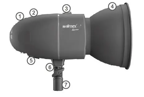
- Overview about the parts Photo Cell (hidden)
- Ventilation Slots
- Unlocking Lever
- Reflector
- Main Switch O/l (OFF/ON)
- Umbrella Holder
- Tripod shot
- The Photo Cell is below the red, transparent cover on the top side of the device
Quick start guide
Keep the sequences of the following opera- tion steps when using the device for the first time to avoid damages on the device.
WARNING
Please note the safety notes in the respective chapters throughout operation.
- Demount protection cap
- Mount reflector.
- Insert modeling lamp.
- Mount reflex umbrella optional
- Connect to power supply.
- Switch on device .
- Adjust, switch off the modelling light.
- Adjust flash output.
- Adjust audio button.
- Prepare flash trigger.
- Mount on tripod optional.
- Radio remote triggering.
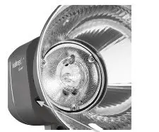
Demount and mount protection cap
Posterior danger of bursting of flash tube Make sure not to touch the flash tube with bare hands accidentally.
Demount protection cap
- Push back unlocking lever and keep pressed.
- Turn protection cap anticlockwise as far as it will go and take off from the device.
- Release the unlocking lever.
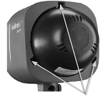
Mount protection cap
Let the device cool down. Fire danger through overheating. Danger of burning. Let the device cool down for approx. 30 minutes. Push back unlocking lever and keep pressed. Plug in the protection cap into the three openings on the device, turn it lockwise and listen for the cap to snap into place. Release the unlocking lever.
Mount and demount reflector
Posterior danger of bursting of flash tube Make sure not to touch the flash tube with bare hands accidentally.
Mount reflector
Switch off device. See Switch the device on and off. Let the device cool down. Danger of burning on reflector, modeling lamp and flash tube let the device cool down for approx. 30 minutes. Demount and mount protection cap. Push back unlocking lever and keep pressed. Plug the refector into the openings, so that the opening for the reflex umbrella (optional) faces downwards. Tun the reflector clockwise and listen for the reflector to snap into place. Release the unlocking lever.
Demount reflector
Danger of burning on reflector, modeling lamp and filash tube. Please let the device cool down tor approx. 30 minutes. Push back unlocking lever and keep pressed. Turn the reflector anticlockwise as far as it will go and take off from the device. Mount protection cap.
Insert, remove the modelling light
Posterior danger of bursting of flash tube through skin oil Never touch the flash tube with your bare hands
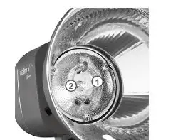
- Modeling Lamp Socket
- Switch off device.
- Pug oft power cord.
- Let the device cool down.
Danger of burning on reflector, modeling lamp and flash tube. Please let the device cool down for approx. 30 minutes. 4. Insert the modelling light When the protection cap is mounted: Demount protection cap. Plug the modelling light carefully into the socket.
Connect to power supply
Only connect the device to an earthed socket.
- Switch off device.
- Compare the local power supply with the connected load of the device. If the values differ, please contact [email protected] or tel. +49 843294890.
- Connect the power cord with the socket on the device and with the power socket.
Switch the device on and off
When the protection cap is mounted: Demount protection cap. Danger of fire through heat accumulation. Never use the device with mounted protection cap
Switch on device
- Set main switch on I (ON).
- The digital display OUTPUT POWER shows the currently adjusted flash power.
- The standby display LED lights up when the adjusted flash power is reached.
- An integrated soft-start prevents the flash tube from damage. It will take 1-2 seconds until the flash output is reached.
- The modelling light will come on if it was switched on when the device was switched off.
- The signal LED AUDIO lights up, if the acoustic operational readiness was switched on.
- The SLAVE function LED lights up, when the photo cell had been switched on.
Switch off device
Place the main switch in the O (OFF) position. All signals will go out. When the modeling lamp was switched on:
The modeling lamp will go out.
NOTE
After switching it off, any residual current in the device is released by way of an electronic discharger. You cannot switch this safety function off. The device does not flash after the flash power has been changed.
Adjustments
Adjust flash output
You can adjust the power of the flashes according to the below mentioned chart.
| Check value | F-stops |
| 6,0 | 1 (full output) |
| 5,0 | 1/2 |
| 4,0 | 1/4 |
| 3,0 | 1/8 |
| 2,0 | 1/16 |
| 1,0 | 1/32 |
- Switch on device.
- Press the button or the button, until the digital display OUTPUT POWER shows the desired flash output. When the device reaches the adjusted flash output, LED TEST lights up.
- Trigger test flash: Press push-button TEST. The LED TEST signal goes out and lightsup not until the device will reach the adjusted flash output again.
Switch the modelling light on and off
The modelling light can only be switched on or off.
- Switch on the device.
- Switch device on/off
- Press the MODEL button. The modelling light comes on. The LED MODEL lights up.
- Switch the modelling light off Press the MODEL key, until the LED MODEL goes out. The modelling light goes out. The LED MODEL goes out.
- Switch on device.See Switch the device on and off.
- Switch on audio signal: Press push-button AUDIO. The LED AUDIO lights. A short beep can be heard when reaching the adjusted flash output.
- Switch off audio signal: Press push-button AUDIO. The LED AUDIO goes out. After triggering a flash, the modeling lamp goes out for a while and lights up again,
when the device has reached the adjusted flash output again.
Prepare and adjust flash trigger
Prepare flash trigger through camera
NOTE
Please note the user information of the camera manufacturer for flash synchronisation.
- Connect sync cord (included in delivery with the connecting socket on the device.
- The other end of the sync cord should be connected with the PC jack socket of the camera.
Prepare flash trigger through remote receiver (optional)
Please note the user information of the remote receiver manufacturer. Connect the cable of the remote receiver with the socket for the sync cord. Switch on and off of flash trigger through built-in photo cell The photo cell enables the device to trigger through another external device on-camera flash devices with integrated
preflashes
- Switch on device. Switch the device on and off.
- Switch on photo cell: Press push-button SLAVE. The LED SLAVE lights.
- Switch off photo cell: Press the SLAVE button, until it goes out. Flash triggering via the integrated radio receiver with the walimex pro remote control Excellence.
Adjusting the channels on the studio flash
You can choose from 16 different channels (F0, F1, F2, F3, … , FF).
- Press the SLAVE button on the studio flash for about 4 sec.
- The display shows C. Press the SLAVE button once again, to access the adjustment F radio channel
- Use the arrow keys to adjust the corresponding channels.
- Press the SLAVE button once again for approx. 5 sec to save the selected channel. Or wait approx. 15 seconds, until the display changes to the start page.
Adjusting channels on the remote control (option)
Open the battery compartment cover. Adjust the studio flash to the remote control by displacing the pins accordingly
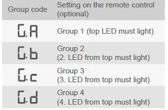
Adjusting the group function on the studio flash
In order to avoid alternating interference signals, they can be adjusted in 4 different groups in total.
- Press the SLAVE button on the studio flash for about 4 sec.
- The display shows “C..”. Press the SLAVE button 2 times to access the adjustment G group.
- Use the arrow keys to adjust the desired group Ga, Gb, Gc or Gd.
- Press the SLAVE button once again for approx. 5 sec to save the selected group. Or wait approx 15 seconds, until the display changes to the start page.
The following table shows how to correctly adjust the setting between transmitter and receiver in the studio flash to one another
Mount on tripod (optional)
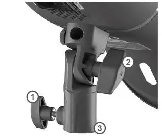
The tripod with the mounted device has a tilt and skid resistant stand.
- Fastening Screw
- Locking Knurl tripod shot
- Tripod Mount pen locking knurl
- Mount the device on the tripod.
- Tighten locking knurl.
- Use locking screw for the correct inclination angle.
Mount reflex umbrella optional
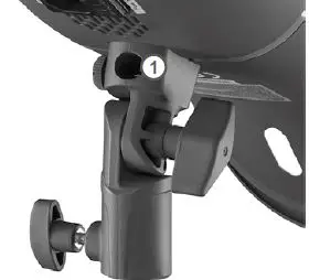
Just use reflex umbrellas with a rod diameter of 8-10mm.
Umbrella Holder
Let the device cool down.
WARNING
Danger of burning on reflector, modeling lamp and flash tube. Please cool down approx. 30 minutes.
Open locking knurl.
Insert the rod of reflex umbrella through the opening in the reflector into the fixture as far as it will go. Tighten locking knurl
NOTE
Don not tighten the locking knurl too tight as to avoid damages on the reflex umbrella.
Switch on and off of modeling lamp
- Switch on device.
- Switch on modeling lamp
- Press push-button MODEL once.
- The modeling lamp switches on.
- The LED MODEL lights.
- Switch off modeling lamp: Press the push-button MODEL, until the LED MODEL goes out.
- The modeling lamp goes out.
- The LED MODEL goes out.
NOTE
If you do not switch off the modelling light before you switch off the device, the modelling light switches on automatically when you switch the device back on.
Trigger the flas
Fire danger through overheating. Continuous rapid sequences of flashes from more than 8 flashes per minute with high flash output could overheat and damage the device. Heat accumulation could be the result when using small, narrow reflectors e.g. snoots or grid reflectors at high power with the device pointing downwards. Continuous increasing and decreasing of the flash output can heat up the device additionally
- Avoid continuous rapid sequences of flashes from more than 8 flashes per minute with high flash output.
- Do not use the device in vertical directi- on, when making rapid flash sequences and high flash output with a small, narrow reflector or grid reflector.
- Do not increase and decrease the output unnecessary.
- Switch on device.
- Modeling lamp is switched on and off according to requirements.
- Trigger flash according to the prepared type of flash trigger.
- Do not flash over 12 shots per minute for over 10 minutes.
- Do not flash over 10 shots per minute for over 30 minutes.
- Do not flash over 8 shots per minute for over 60 minutes.
- In the above mentioned cases, let the device cool down for at least 15 minutes.
- Don´t switch off the device during the 15 minutes cooling time as to avoid the interruption of the cooling
- Don´t trigger a flash during the 15 minutes cooling time, neither with reduced flash output.
- Switch off the modeling lamp.
- When the signal warning of overheating and overloading beeps: Reduce the flash output or flash sequence.
- If the continuous beep don´t stop: Let the device cool down for at least 30 minutes.
- Don´t switch off the device during the 30 minutes cooling time as to avoid the interruption of the cooling
- Don´t trigger a flash during the 30 minutes cooling time, neither with reduced flash outp
- Switch off the modeling lamp.
Transportation and storage
- Switch off device. See Switch the device on and off.
- Let the device cool down completely.
WARNING
Fire danger through hot parts. Let the device cool down completely. Demount reflector and all power and connecting cables. Clean the device if necessary. See Cleaning. Mount the protection cap. Put the device and all demounted ele- ments into the original styrofoam box and carry and store them according to the equirements in the technical specifica- tions. See Technical specifications.
Solve problems
Problem
Flash device is switched on, but has no function
Possible reason
Power cord is not plugged or plugged T incorrect. Micro fuse is defect Remedy .Plug in the power cord correctly. Change micro-fuse, see Change micro-fuse
Problem
Flash shows functions, but flash triggering not possible
Possible reason
Flash capacitor is defect
Remedy
Contact our service department
Problem
Modelling light flickers
Possible reason
Modelling light defective
Remedy
Replace the modelling light, see “Insert, remove the modelling light”
Problem
Radio triggering facility not available
Remedy
Adjust the studio flash using the radio remote control. Change the remote control battery.
The following notice is shown in the display
- E1 Problem with operation temperature. Switch off the device immediately. Contact the service department.
- E2 Problem with power output. Switch off the device for approx. 30 minutes. Danger of overloading
- E3 Internal voltage inside the flash is too high. Switch on/off the flash. If you still have the defect, contact the service department.
Maintenance
Continuous inspection and maintenance of the device
Inspect all cables and plugs for damage
Danger of electric shock and danger of fire due to short circuit.
Have the device repaired by an electrician immediately. Please load the flash capacitor as required
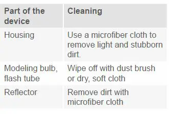
Cleaning
Posterior danger of bursting of flash tube. Make sure not to touch the flash tube with bare hands accidentally.
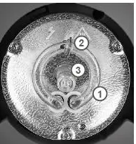
Change flash tube
Please just use flash tubes, which are conform with the required specifications as to avoid the bursting of the flash tube.
WARNING
Posterior danger of bursting of flash tube Do not touch the flash tube with bare hands. Wear clean cotton gloves or use a clean cloth
Discharge device
- Danger of electric shock.
- Discharge the device before changing the flash tube.
- Switch on device.
- Trigger flash: Press push-button TEST and switch off main switch immediately
- If you don´t switch off the main switch within 0,5 seconds, the device will charge anew.
- Unplug power cord.
- Let the device cool down anger of burning on reflector, modeling lamp and flash tube. Please let the device cool down for approx. 30 minutes.
Remove old flash tube Demount reflector
- Take out the modelling light: Insert, remove the modelling light
- Hook off the retention clip with pliers.
- Hold the flash tube at the right and left side of the socket.
CAUTION
Danger of cutting and splitting through breaking flash tube. Just touch the flash tube in the range of the plug in contact and not at the levitated flash ring. Agitate the flash tube carefully and pull it 4. Attach new flash tube: Place the two plug-in contacts of the flash tube loose into the socket. Press the flash tube with even, slight pressure on the plug-in contacts into the socket as far as it goes. Press the two plug-in contacts carefully and even into the socket as to avoid the
deformation of the wires.
- Hook in the retention clip with pliers.
- Insert in modeling lamp.
- Mount reflector.
Change micro fuse
WARNING
Danger of electric shock and fire through short circuit
A micro fuse, which is not conform with the required specifications, does not protect against the overloading of the device. Please just use a micro fuse, which is conform with the required specifications.
NOTE
The fuse holder keeps a spare fuse.
- Switch off device.
- Disconnect from power supply: Unplug power cord.
- Open fuse holder: Use a small screwdriver to lift up the fuse holder carefully and slightly.
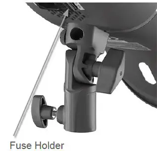
Pull out the fuse holder with your handscompletely out of the slot. Take out the old micro fuse. Take the new micro-fuse out of the spare slot and slide it in the center of the holder. Slide the fuse holder carefully into the slot s far as it goes.
Charge flash capacitor
Charge the flash capacitor completely, when you have used the device several days mainly with reduced output when you didn´t use the device for several months. Thus, you can protect the life expectancy of your flash capacitor and ensure a continuous optimal power output. Switch on device. The modeling lamp can remain switched off. . Adjust maximal flash output.Press the ⏶ button, until the digital display OUTPUT POWER shows the value 6.0. The standby indicator LED lights up. The device should remain switched on at least 30 minutes. Re adjust the flash output on the desired value.
Disposal and environmental protection
Please dispose of your device at your local disposal area at no charge.
Technical specifications
| Studio flash Newcomer | 100 | 150 | 200 | 300 |
| Flash power / Nominal output | 100Ws | 150Ws | 200Ws | 300Ws |
| Guide Number (2m/ISO 100) | 30 | 40 | 50 | 60 |
| Output | Full to 1/32 | |||
| Recycling Time | 0,3 ~ 1,2 s | 0,4 ~ 1,3 s | 0,5 ~ 1,8 s | 0,6 ~ 2,0 s |
| Flash Duration | 1/800 ~ 1/1200 Sec. | |||
| Modeling Lamp | 75 W | |||
| Trigger Method | Photo cell, sync cord, test button, remote control | |||
| Colour Temperature | 5600 K ±200 | |||
| Flash Tube | Plug-in, user replaceable | |||
| Trigger Voltage | 4,5 V | |||
| Cooling | no | |||
| Automatic Discharge | yes | |||
| Power Supply | AC 220 – 240 V / 50 Hz | |||
| NOTE Only connect the device to an earthed socket. | ||||
| Accessories | Reflector, power cord (4 m), sync cord, modeling lamp | |||
| Weight | 0,75 kg | 0,85 kg | 0,90 kg | 1,00 kg |
| Dimensions | 20 x 12 x 12 | |||
| Micro-fuse | T 4A H – 250V | |||
| Protection class | IP 20 | |||
| Radio frequency | 2,4 GHz | |||
| Permitted Operation Temperature | -10 °C to + 40 °C | |||
| Storage Conditions | Dry and dust-free in the original packing at -20 °C to +50 °C | |||
Overview about the operation panel
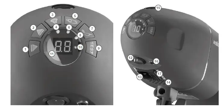
| 1 | Push-button 6 | 10 | Standby display LED |
| 2 | Push-button 5 | 11 | Digital Display OUTPUT POWER |
| 3 | Push-button MODEL | 12 | Main Switch (OFF/ON) |
| 4 | LED MODEL | 13 | Socket for power cord |
| 5 | Push-button SLAVE | 14 | Ventilation slots |
| 6 | LED SLAVE | 15 | Photo cell |
| 7 | Push-button AUDIO | 16 | Connecting Socket for sync cord |
| 8 | LED AUDIO | 17 | Fuse holder |
| 9 | Push-button TEST |
|
Spare parts
| 1 | Push-button 6 | Modelling light power setting/ settings for radio remote triggering |
| 2 | Push-button 5 | Modelling light power setting/ settings for radio remote triggering |
| 3 | Push-button MODEL | Switches the modelling light on/off |
| 4 | LED MODEL | Lights when the modelling light is switched on. |
| 5 | Push button SLAVE | Switch on and off for photo cell |
| 6 | LED SLAVE | Lights when the photo cell is switched on. |
| 7 | Push button AUDIO | Switches the acoustic beeper button on |
| 8 | LED AUDIO | Lights when the audible standby indication is switched on. |
| 9 | Push button TEST | Triggers a test flash |
| 10 | Standby display LED | Lights when the adjusted flash power is reached (device ready for flashing) |
| 11 | Digital Display OUTPUT POWER | Shows the control value for flash power |
| 12 | Main Switch O/I (OFF/ON) | Switches the device on and off |
| 13 | Socket for power cord | Connection for external power supply |
| 14 | Ventilation slots | This cools down the flash electronics. |
| 15 | Photo cell | To trigger the photo cell |
| 16 | Connecting Socket for sync cord | Connection socket for sync cord or remote receiver optional |
| 17 | Fuse holder | Contains the micro fuse and spare fuse |
| Part of the device | Item number |
| Remote Control Excellence | 19899 |
| Flash Tube VT-100/150/200 | 18458 |
| Flash Tube VT-300 | 18466 |
| Modeling Lamp, 75W | 23110 |
| Sync Cord 420cm with Phone Jack 6,3mm | 12795 |
| Standard Reflector shiny | 16242 |
| Power Cord 4m with IEC Connector | 12914 |
Reference to the Declaration of Conformity
WALSER GmbH & Co. KG. hereby declares that this radio remote receiver is compliant with the general requirements and all other applicable regulations of the directive 2014/53/EU”. The Declaration of Conformity is available from the following address: [email protected]


