
POTTER DCA-10025 SCA and DCA Single Channel and Dual Channel Amplifier

Installation Wiring Documents
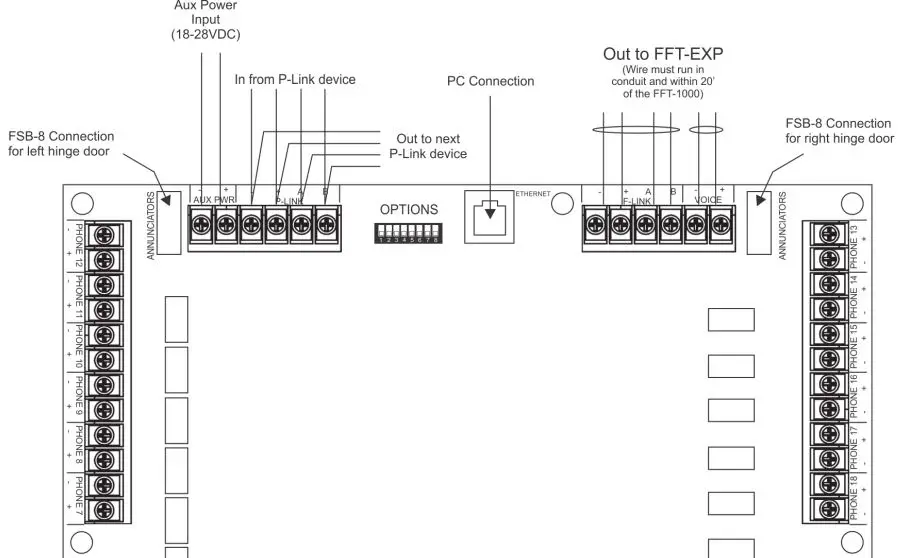
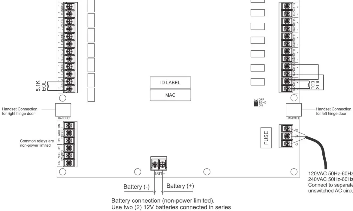
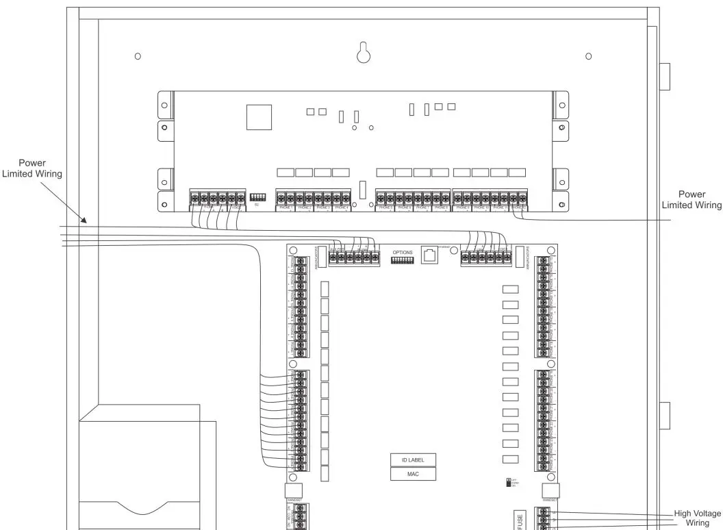
Figure 1. FFT-1000 Fire Fighter’s Telephone Panel Wiring Diagram
| Type of Circuit | Voltage Type | Power Type |
| AC Connection | High Voltage | Non-Power Limited |
| Battery Connection | Low Voltage | Non-Power Limited |
| Trouble Relay | High Voltage | Non-Power Limited |
| Low AC Relay | High Voltage | Non-Power Limited |
| Aux Power | Low Voltage | Power Limited |
| P-Link | Low Voltage | Power Limited |
| F-Link | Low Voltage | Power Limited |
| Phone Circuits | Low Voltage | Power Limited |
Main Supply Circuit
The AC terminals are located in the lower right hand portion of the main board. The main board supervises the main
AC power and provides indication that the AC power is absent.
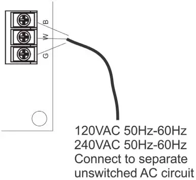
The terminals are rated at 120 VAC/240 VAC 50/60 Hertz and are marked so accordingly on the board. The earth ground connection is marked as “G” and is the furthest connection from the line voltage connection.
The AC input power ratings:
Maximum of 675 mA at the nominal 120 VAC rating.
Maximum of 80 mA at the nominal 240 VAC rating.
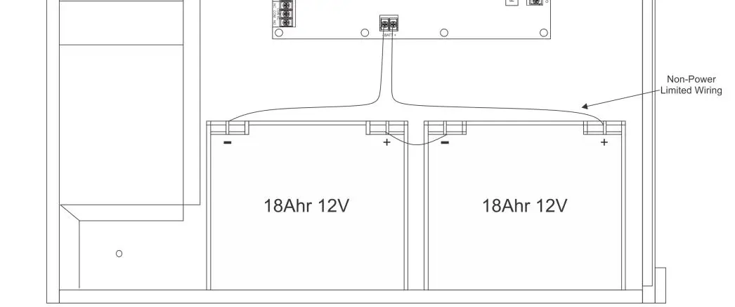
Rechargeable Battery Circuit
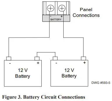
The battery charging circuit is provided in the bottom portion of the board. Terminal connections are provided to connect wire leads for battery connection. The battery must be a recognized or listed sealed lead acid battery or equivalent.
The battery charging voltage is approximately 27.3 VDC and the circuit is supervised. The battery circuit is protected with a non-replaceable 7 amp poly switch located on the main circuit board. The maximum battery charging circuit is 1.0 amp DC.
The battery circuit is rated for 8 to 55 AH batteries and the cabinet will house up to two 18 AH batteries. The batteries will operate the panel for at least 24 hours and 5 minutes of alarm. To determine the minimum size batteries for standby and alarm times desired, the installer must complete a battery calculation work sheet to determine the minimum battery size for a particular application. For reference, the battery calculation work sheet is attached as Appendix A. Complete standby battery calculations must be completed to ensure adequate battery sizes are provided.
Technical Specifications
| Standby Current | 154 mA |
| Active Current | 255 mA |
| FFT-1000 Voltage | 24V DC |
| Operating Temperature Range | 32° to 120° F (0° to 49°C) |
| Operating Humidity Range | 10% to 93% (non-condensing) |
Separation of Circuits – Power Limited, Non-Power Limited, High Voltage Wiring
The main AC power connection is considered high-voltage and non-power limited. The Battery conductors, and the low AC and trouble relays are nonpower limited. All remaining circuits are low-voltage, power limited connections.
Proper separation must be maintained between the circuits listed above. All separations in the different wiring must be maintained by at least 0.25 inches and the wire insulation must be for the higher voltage.
In the panel there are sufficient knock outs located around the periphery of the cabinet to allow the installer to maintain power limited and non-power limited connections.
Phone Circuits
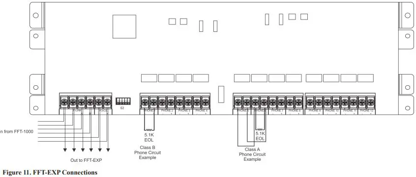
The FFT-1000 is equipped with 24 Class B or 12 Class A phone circuits and can be expanded upon by adding an FFT-EXP for an additional 12 Class B or 6 Class A circuits. All circuits are provided with a 5.1K resistor. All phone circuits are low voltage, supervised, and power limited. FFT phone circuits are rated 24VDC 60mA max.
Wire Impedance = 50 ohms
Relay Outputs
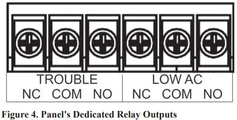
The panels have two dedicated common relays, Trouble and Low AC.
The contact rating is 24VDC / 3.0A, 125VAC / 3A, Power Factor: 1.0. These outputs are non-power limited and not supervised. However, they are power-limited if the power supply to the connected devices is power-limited.
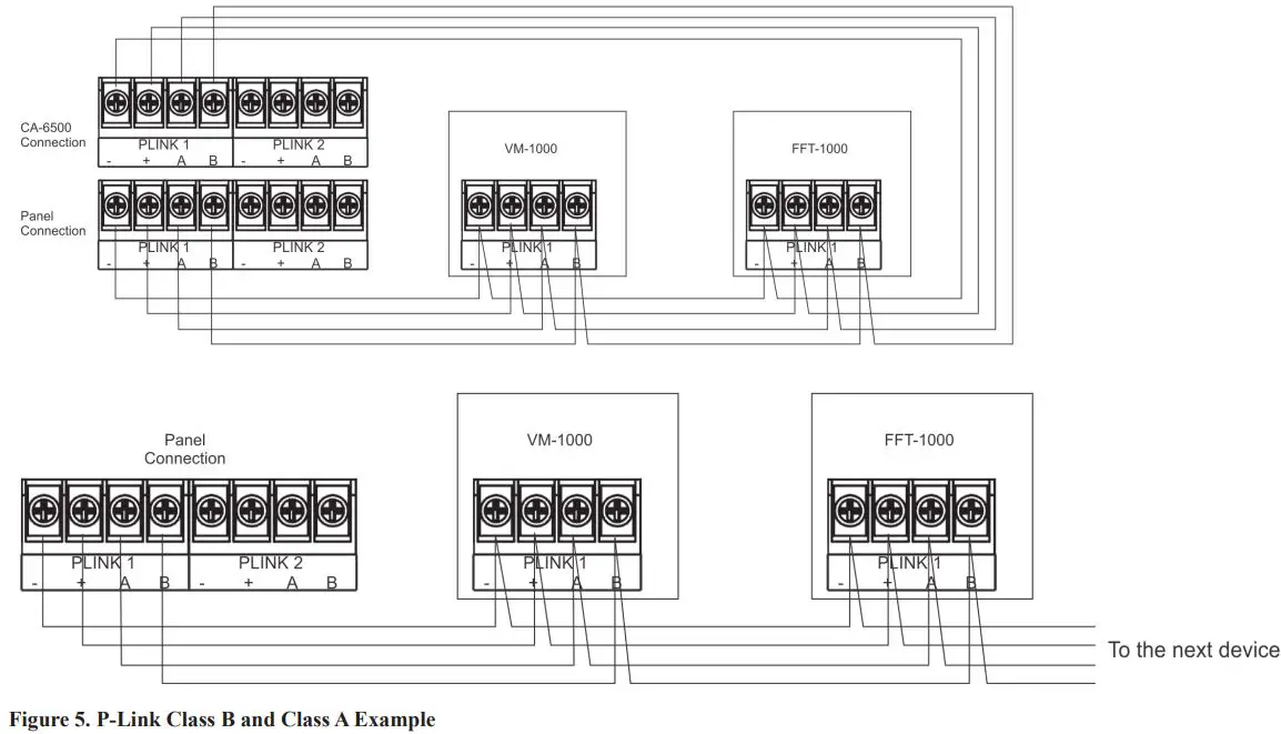
P-Link
The FFT-1000 can operate as a standalone system or it can operate in conjunction as an expansion device with the IPA-4000V via P-Link.
All expansion devices are supervised via the RS-485 connection. Wiring is fully supervised, and power limited. Any connection to ground of 0 ohms will be annunciated as a ground fault.
P-Link Voltage = 24 VDC
Maximum wire length = 6,500 feet.
Maximum wire resistance = Maximum wiring resistance is based on load.
Calculate using the following equation
(Total P-Link Alarm Current) x (Wire Resistance) < 6 volts.
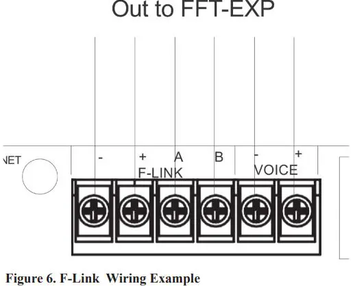
F-Link and VOICE
The F-LINK is a proprietary communication bus to interface exclusively to the FFT-EXP to add additional phone circuits. Wiring is fully supervised, and power limited. Any connection to ground of 0 ohms will be annunciated as a ground fault. F-Link and VOICE connections between the FFT-1000 and FFT-EXP must be within 20′ and run in conduit.
F-Link Voltage = 24V
Maximum wire length = 20 feet
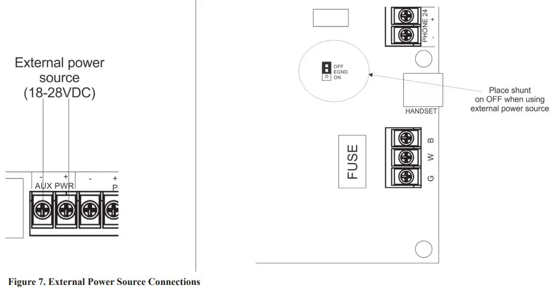
AUX PWR
The AUX PWR terminal provides an alternative option to power the FFT-1000 using a 24VDC external power source. The AUX PWR input in unsupervised and power limited.
General Wiring Information
The cabinet has various conduit knockouts located around the cabinet for ease of wire installation. In addition, this method provides a means to separate different types of circuit to reduce electrical interference, transient voltage, or voltage ratings.
The enclosure requires the use of power limited and non-power limited wiring on the main board as well as within the enclosure. Power limited wiring is to remain separated from non-power limited by a minimum or 0.25 inches and all cablings should be insulated to the higher voltage.
When the panel is installed, the National Electrical Code (NEC, NFPA 70) should be followed for the proper installation and separation of power limited and non-power limited circuits. The mixing of power limited, and non-power limited should be avoided. Refer to the following figure for suggested wiring routing.
Functionality
The system is completely supervised and is designed to comply with UL 864 and UL 2572.
The FFT-1000 is Fire Fighter Telephone panel that provides the ability to establish 2-way phone communication between the main FFT-1000 and the remote fireman’s handsets. The panel is equipped with 24 Class B or 12 Class A phone circuits that are fully supervised and programmable through Potter software. A maximum of 96 Class B or 96 Class A phone circuits can be utilized in a system by adding the FFT-EXP expansion module. All phone circuits are shipped with a 5.1K EOL resistor.
The FFT-1000 is equipped with a proprietary P-Link communication bus to operate in conjunction with an IPA-4000V. The panel is also designed to operate as a standalone system.
The panel is also equipped with a proprietary F-Link communication bus to interface with the FFT-EXP phone circuit expansion module.
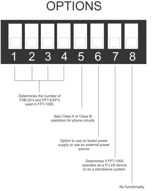
The OPTIONS switch bank defines the number of FSB-24’s and FFT-EXP’s utilized in the FFT-1000. It also provides an option to use the on board AC power supply or alternatively connect to a 24VDC external power source, and to select Class A or Class B operation.
The OPTIONS switch bank functions:
Class B Phone Circuits
| Switch 1 | Switch 2 | Switch 3 | Switch 4 | Circuits | # of FSB-24 | # of FFT-EXP |
| OFF | OFF | OFF | OFF | 1-24 | 1 | 0 |
| ON | OFF | OFF | OFF | 25-36 | 2 | 1 |
| OFF | ON | OFF | OFF | 37-48 | 2 | 2 |
| ON | ON | OFF | OFF | 49-60 | 3 | 3 |
| OFF | OFF | ON | OFF | 61-72 | 3 | 4 |
| ON | OFF | ON | OFF | 73-84 | 4 | 5 |
| OFF | ON | ON | OFF | 85-96 | 4 | 6 |
Class A Phone Circuits
| Switch 1 | Switch 2 | Switch 3 | Switch 4 | Circuits | # of FSB-24 | # of FFT-EXP |
| OFF | OFF | OFF | OFF | 1-12 | 1 | 0 |
| ON | OFF | OFF | OFF | 13-18 | 1 | 1 |
| OFF | ON | OFF | OFF | 19-24 | 1 | 2 |
| ON | ON | OFF | OFF | 25-30 | 2 | 3 |
| OFF | OFF | ON | OFF | 31-36 | 2 | 4 |
| ON | OFF | ON | OFF | 37-42 | 2 | 5 |
| OFF | ON | ON | OFF | 43-48 | 2 | 6 |
| ON | ON | ON | OFF | 49-54 | 3 | 7 |
| OFF | OFF | OFF | ON | 55-60 | 3 | 8 |
| ON | OFF | OFF | ON | 61-66 | 3 | 9 |
| OFF | ON | OFF | ON | 67-72 | 3 | 10 |
| ON | ON | OFF | ON | 73-78 | 4 | 11 |
| OFF | OFF | ON | ON | 79-84 | 4 | 12 |
| ON | OFF | ON | ON | 85-90 | 4 | 13 |
| ON | ON | ON | ON | 91-96 | 4 | 14 |
Class A or Class B Phone Circuits Selection
| Switch 5 | Operation |
| OFF | Class B Phone Circuits |
| ON | Class A Phone Circuits |
On Board Power Supply or External Power Source Selection
| Switch 6 | Operation |
| OFF | Use on board power supply |
| ON | Use external power source |
P-Link Device or Standalone System
| Switch 7 | Operation |
| OFF | FFT-1000 does not use P-Link connection (Standalone System) |
| ON | FFT-1000 operates as P-Link Device |
- The Ethernet jack is used for firmware upgrades on standalone panels.
- The panel includes two relay contacts for additional monitoring functions: Trouble and Low AC.
- Trouble – This failsafe relay changes state during any trouble condition. This relay is not programmable and no additional mapping to this relay can take place.
- Low AC – The relay changes state during any detection of AC failure and brownout. This relay is not programmable and no additional mapping to this relay can take place.
The panel is equipped with an FSB-8 user interface to easily view status and fault indications and push buttons for common user functions. The common user function buttons are the following: - SILENCE – When a fault condition is detected, the fault piezo will sound to indicate that an active trouble is present. When the SILENCE button is pressed, it will silence the fault piezo.
- MUTE – When the MUTE button is pressed, the local handset at the FFT-1000 will be muted. By pressing the mute button, again, it will unmute the handset.
- TEST – When the TEST button is pressed, a lamp test will perform on the FSB-8.
- The LED indicators are the following:
- POWER – When AC is detected, the power LED will illuminate green. When AC is low or not detected, the LED will disable.
- GENERAL FAULT – The general fault LED is off when no trouble(s) are indicated. The LED will illuminate amber when an active trouble is present.
- EARTH FAULT – The earth fault LED is off when no ground fault is indicated. The LED will illuminate amber when an active ground is present. **Note** The earth fault LED is not used when system is operating Aux-Power mode.
- BATTERY FAULT –The battery fault LED is off to indicate the battery and charging circuit is operating normally. The LED will illuminate amber to indicate low battery, missing battery and/or inoperable charging circuit. **Note** The earth fault LED is not used when system is operating Aux-Power mode.
- HANDSET FAULT – The handset fault LED is off to indicate the local handset is connected. The LED will illuminate amber to indicate local handset is not connected.
- EXPANDER FAULT – The expander fault LED is off to indicate all FFT-EXP’s are operating normally. The LED will illuminate amber to indicate a missing FFT-EXP.
- SILENCED – The silenced LED indicates all trouble conditions have been silenced.
The FFT-1000 is equipped with a supervised FSB-24 which provides 24 programmable buttons to view and answer incoming calls. Each button has two corresponding LEDs to indicate incoming calls and fault conditions. The FFT-1000 can support four (4) FSB-24, offering a total of 96 push buttons.
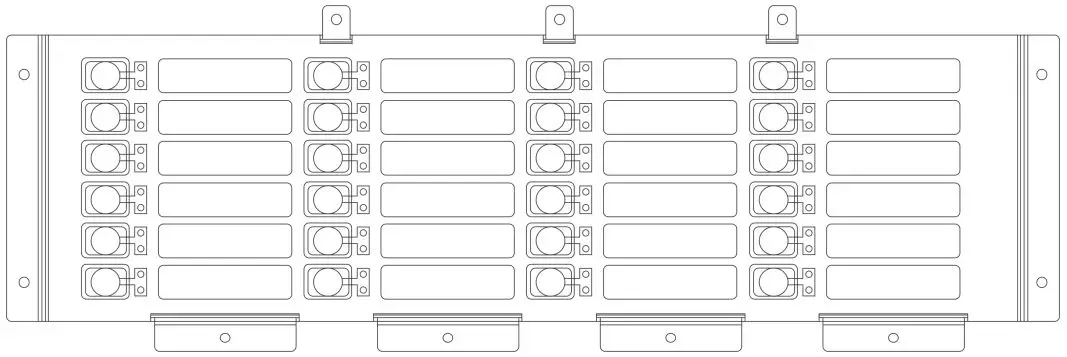
In standby, all LEDs are off to indicate no remote handsets are connected. When a remote fireman’s handset is connected to a phone jack, the FFT-1000 will ring and the associated LED on the FSB-24 will flash green indicating an incoming call. By selecting the corresponding switch, the LED will illuminate solid green indicating the call has been acknowledged.
When there is an active trouble on a phone circuit, the associated LED on the FSB-24 will illuminate solid yellow. The LED will clear once the fault has been restored.
The FFT-1000 may utilize an FFT-EXP to add additional phone circuits. The FFT-EXP provides 12 Class B or 6 Class A phone circuits which are programmable and fully supervised. The FFT-1000 can support up six (6) FFT-EXP for Class B systems and fourteen (14) FFT-EXP for Class A systems. The FFT-EXP communicates with the FFT-1000 via the F-LINK and VOICE bus.
A maximum of two (2) FFT-EXP’s can be mounted within the FFT-1000. Additional FFT-EXP’s may be mounted in the AE-8 and AE-14 remote cabinets. All FFT-EXP’s must be installed in the same room within 20 feet of the FFT-1000 and wiring must run in conduit.
AE-8 (Part Number 3992675) – A maximum of four (4) FFT-EXP’s can be stored in the AE-8 enclosure.
AE-14 (Part Number 3992676) – A maximum of six (6) FFT-EXP’s can be stored in the AE-14 enclosure.
3. Programming Options
The FFT-1000 is configured using the PC based programming tool. The panel stores the site specific configuration data in non-volatile memory.
Appendix A: Battery Calculation Worksheets
| Description | Quantity | Standby (mA) | Total Standby (mA) | Alarm (mA) | Total Alarm (mA) |
| FFT-1000 | 1 | 146 mA | 146 mA | 255 mA | 255 mA |
| FSB-8 | 1 | 4 mA | 4 mA | 13 mA | 13 mA |
| FSB-24 | 1 | 4 mA | 27 mA | ||
| FFT-EXP | 56 mA | 166 mA | |||
| Total (mA) | Total (ma) | ||||
| Convert to Amps | x 0.001 | Convert to Amps | x 0.001 | ||
| (*Refer to maximum allowable standby current) Total A: | Total A: | ||||
|
Multiply by standby hours |
x | 60 minutes per hour Alarm time (minutes) Example: 5 minute alarm: enter 12 10 minute alarm: enter 6 |
÷ | ||
| Total Standby AH | Total Alarm AH | ||||
| +Total Standby AH | |||||
| Total AH | |||||
| Efficiency Factor | ÷ 0.80 | ||||
| Required AH | |||||
| *Maximum Allowable Standby Current (UL 24-Hour standby time) 7 AH .215 A 18 AH .582 A 33 AH 1.082 A 55 AH 1.815 A | Important Notes: 1) FACP enclosure can house up to two (2) 18 AH batteries. Larger batteries require accessory enclosure, part #SSU00500. 2) NFPA 72 requires 24 hours of standby power followed by 5 minutes alarm activation. 3) Door holder circuits configured to disconnect upon AC loss need not be included in the battery standby calculation since they will not draw power during that time. Door holders will contribute to standby current draw when AC is present. 4) Total current must not exceed power supply rating (5.0A). 5) LED/Relay/IDC-6 current must be accounted for in the battery calculation for the supplying source. |
Operating Instructions
| Normal Standby | The green POWER LED will be illuminated indicating AC is present. If the AC power is re- moved for more than 5 seconds, the green AC power LED will extinguish. |
| Trouble Condition | When a fault condition occurs, the amber LED will illuminate on a specific fault indicator based on the active trouble condition and the local buzzer will sound until the fault is restored or the TROUBLE SILENCE button is pressed to silence the trouble condition. If the buzzer is silenced and the fault is not restored within 24 hours, the buzzer will resound. |
| Silencing Trouble(s) | When a trouble is occurring, the local buzzer will sound until the TROUBLE SILENCE button is pressed. |
| Ground Fault | When a conductor contacts and earth ground, the amber EARTH FAULT LED will illuminate. |
| 2-Way Phone Communication | In standby, all LEDs are off to indicate no remote handsets are connected. When a remote fire- man’s handset is connected to a phone jack, the FFT-1000 will ring and the associated LED on the FSB-24 will flash green indicating an incoming call. By selecting the corresponding switch, the LED will illuminate solid green indicating the call has been answered. |
| Mute | When the MUTE button is pressed, all microphones on remote handsets will be muted. By press- ing the MUTE, again, will unmute microphones on remote handsets. |
| Testing and Maintenance | Test this system monthly or more frequently as required by the AHJ. Before conducting any testing contact the building personnel and the monitoring facility as applicable. When testing a system configured for releasing, activate the releasing disconnect switch to prevent accidental discharge of a suppression system. Test the circuits as outlined in the Installation Manual. Test in accordance with NFPA 72 Inspection, Testing and Maintenance Chapter(s) and any local require- ments. The batteries should be marked with the date of installation and replaced every four years or sooner if battery trouble occurs. Batteries should be checked with a tester acceptable to the AHJ such as a Stone Technologies model STC612A or equivalent. In case of a fuse replacement, refer to the Installation Manual for the proper rating. Contact the agency below for service or operational questions. |


