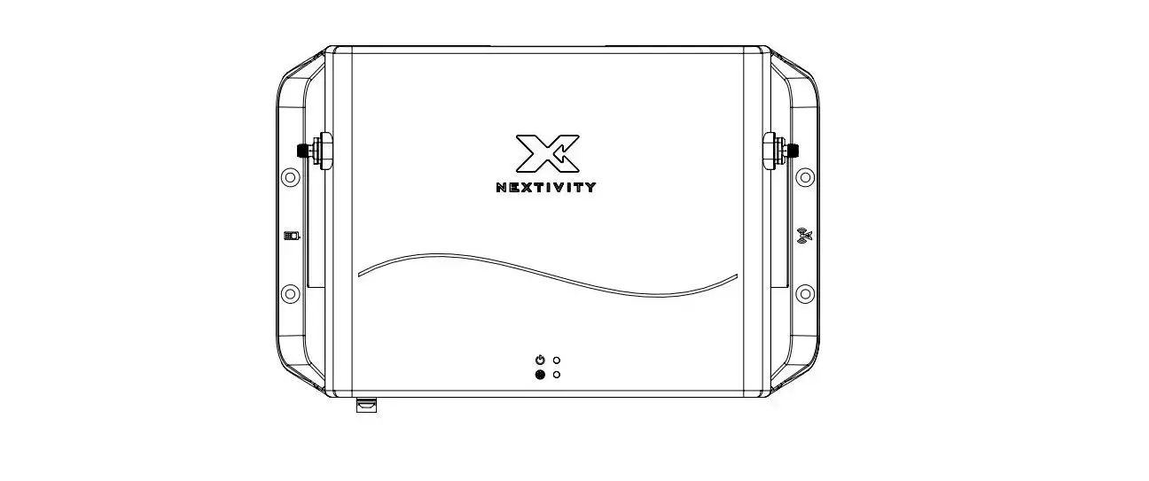
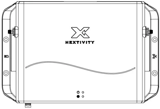
NEXTIVITY G51-LE-001 Smart Signal Booster
Included In the Box
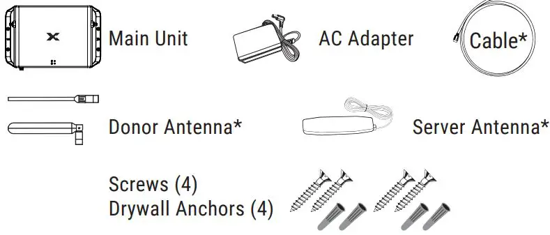
*Included with certain kits only.
IMPORTANT: Your External Modem is an electronic device. It must be kept indoors and in a dry, cool, well-ventilated area.
Quick Installation
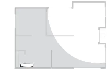
- Select Server Antenna Location

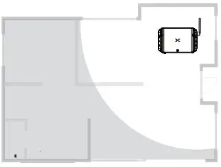
Use your phone to find where coverage is needed. This is where the Server Antenna should be installed on a wall. - Select Main Unit Location
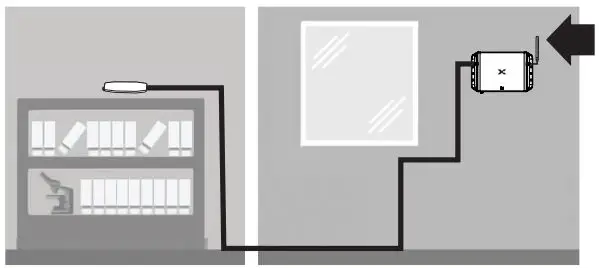
 Place the Main Unit near a window where there is a strong signal. Ideally, the Main Unit should be placed with at least one wall from the Server Antenna and as far as the cable will allow. If the Server Antenna cable is too short, it can be extended with a separate coaxial cable having SMA(m) & SMA(f) connectors.
 - Attach Server and Donor Antennas

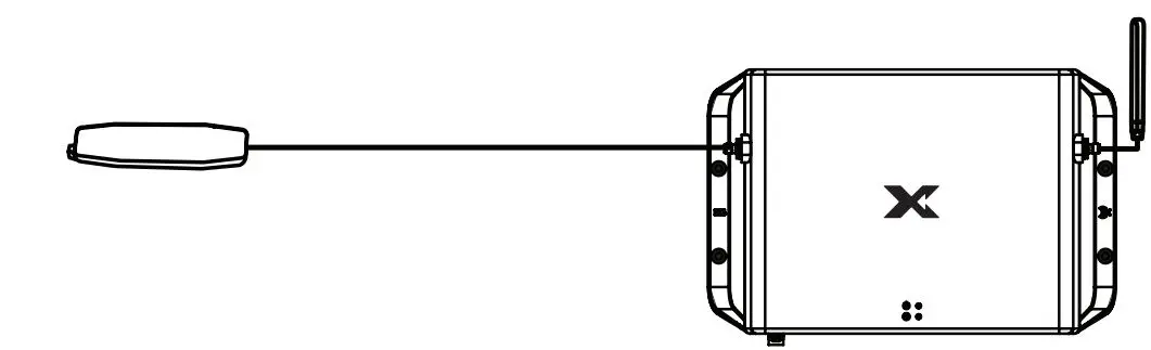
Attach the Donor Antenna and Server Antenna to the Main Unit. Make sure to mount the Server Antenna horizontally.The Donor Antenna should be separated/isolated as far away as possible from the Server Antenna, with greater separation providing best performance.

- Plug In the Main Unit

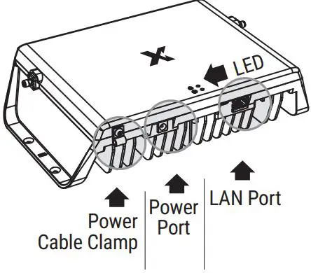
Plug in the Main Unit to power with the included AC Adapter. The LED on the front will blink during set up and turn green when the device is ready. After powering on the device, connect the Power Cable Clamp. - Nextivity WAVE
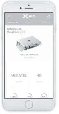
Download the WAVE App to monitor your system status. Connect the Main Unit using category cable to your ISP modem LAN port or external LTE modem to manage via the web interface WAVE Portal.
Scan to Download: The WAVE App is available for smartphones and tablets.
 Place the Main Unit near a window where there is a strong signal. Ideally, the Main Unit should be placed with at least one wall from the Server Antenna and as far as the cable will allow. If the Server Antenna cable is too short, it can be extended with a separate coaxial cable having SMA(m) & SMA(f) connectors.
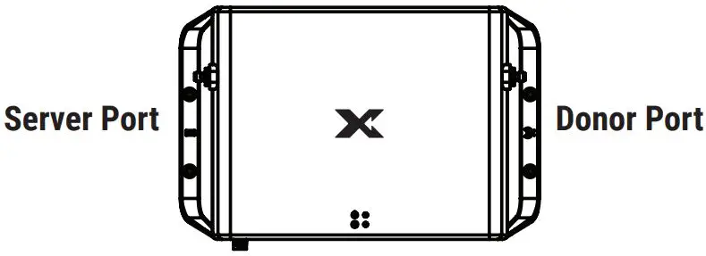

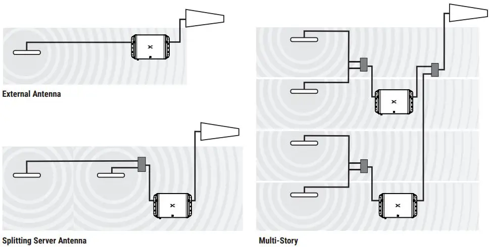
Advanced Installation
For best results, separate the Donor and Server Antenna(s) as much as possible. Antenna separation (isolation) can be achieved with either physical distance or walls and floors between the antennas.
Make sure any cables, splitters, and antennas used in the system are properly matched. (CEL-FI GO G51 is rated for 50 Ω)
Recommended:
- > 20 dB port-to-port isolation for any splitter
Downlink power should be:
- > 0 dBm to use a two-way splitter
- > 3 dBm to use a four-way splitter

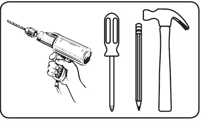
Mounting Instructions
REQUIRED HARDWARE
NOTE: This package comes equipped with Mounting Screws and Drywall Anchors for mounting to the ceiling. Before installing, ensure there are no wires, other objects, or metal plates above the drywall that may interfere with the inserts, screws, or mounted units.
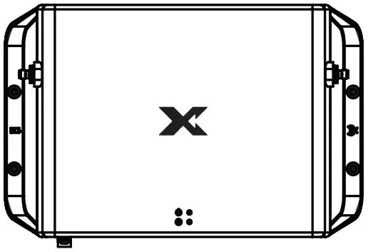
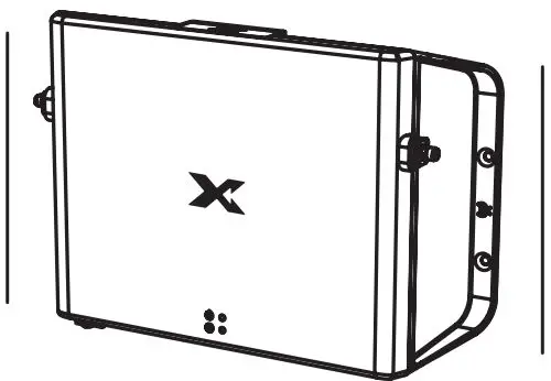
- Determine where to install the Main Unit based on the recommendations in the Quick Installation section.

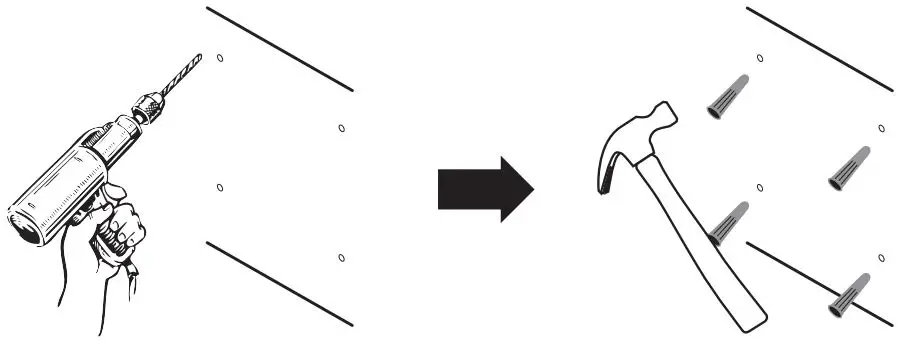
- Mark the four mounting hole locations with a pencil based on where you’ll position the Main Unit.

- In each marked spot, use a 3/16” drill bit to drill guide holes for the Drywall Anchors, and then install the anchors.

- Mount the Main Unit and then attach the Donor and Server Antennas.

| band | link | Output Power | EIRP* |
| 1 | Downlink | 20 (dbm) | 14.8 (dbm) |
| Uplink | 22 (dbm) | 24.1 (dbm) | |
| 3 | Downlink | 20 (dbm) | 14.8 (dbm) |
| Uplink | 22 (dbm) | 24.1 (dbm) | |
| 5 | Downlink | 20 (dbm) | 14 (dbm) |
| Uplink | 20 (dbm) | 22.5 (dbm) | |
| 7 | Downlink | 20 (dbm) | 15 (dbm) |
| Uplink | 22 (dbm) | 24.1 (dbm) | |
| 8 | Downlink | 20 (dbm) | 22.5 (dbm) |
| Uplink | 20 (dbm) | 22.5 (dbm) | |
| 20 | Downlink | 20 (dbm) | 13.8 (dbm) |
| Uplink | 20 (dbm) | 22.5 (dbm) | |
| 28L | Downlink | 20 (dbm) | 13.8 (dbm) |
| Uplink | 20 (dbm) | 22.5 (dbm) | |
| n78 | Downlink | 27 (dbm) | 11.48 (dbm) |
| Uplink | 24 (dbm) | 22.5 (dbm) | |
| Model Number | Bands Supported | ||
| G51-LE | 1, 3, 5, 7, 8, 28L, n78 | ||
| G51-ME | 1, 3, 5, 7, 8, 20, n78 | ||
*Tested with donor antenna (A21-ML3-601) & serverantenna (A41-NL3-101)
Copyright © 2023 by Nextivity, Inc., U.S. Patents pending. All rights reserved. The Nextivity and CEL-FI logos are registered trademarks of Nextivity, Inc. All other trademarks or registered trademarks listed belong to their respective owners. Designed by Nextivity, Inc. in California.


