GOSSEN METRAWATT SU1604 ENERGY Control
Technical data, dimensional drawings, connector pin assignments and order information can be found on the Internet at www.gossenmetrawatt.com under
> Products > Industrial Measuring and Control Technology
> Energy Management > Summators > SU1604
Scope of Delivery
- 1 Module (U1604, U1614 or U1624)
- 1 Split toroidal core (only with U1604)
- Bus connectors (number and type depending on module)
- 1 Condensed operating instructions (this document)
Operating instructions including safety precautions can be found in each respective language at:
https://www.gmc-instruments.de/en/products/industrialmeasuring-technology/energy-management/summators/su1604/
Safety Precautions – Symbols
- A suitable surge protector must be used in order to ensure that the installation site meets the requirements specified for overvoltage category II.
- Check the specified nominal voltage on the serial plate before placing the instrument into service.
- Observe maximum pulse output voltage.
- When wiring the instrument, make sure that the connector cables are not damaged, and that they are voltage-free.
- If it can be assumed that safe operation is no longer possible, the instrument must be immediately removed from service (disconnect input voltage!).
Safe operation can no longer be relied upon if the instrument demonstrates visible damage.
The instrument may not be placed back into operation until troubleshooting and repair have been performed, and calibration and dielectric strength have been tested and approved at our factory or by an authorized service center. - Balancing, maintenance or repair may only be carried out by trained personnel who are familiar with the dangers involved.
- terminals of the U1614 power pack module may only be disconnected or connected in the current and voltage-free state!
- During operation when auxiliary power is active, the U1614 power pack may not be plugged into or unplugged from the TBUS!
- During operation when auxiliary power is active, neither the U1604 basic module nor any other S0 modules may be plugged into or unplugged from the TBUS.
- Opening the housing of the U1614 power pack during operation is impermissible! The fuse may only be replaced in the voltage-free state.
- The TBUS may only be used to connect ECS components. Any combination with non-system devices with similar backplane connection is impermissible.
Meanings of Symbols on the Instrument
![]() Warning concerning a point of danger (attention, observe documentation!)
Warning concerning a point of danger (attention, observe documentation!)
![]() The instrument may not be disposed of with household trash. Further information can be accessed on the Internet at www.gossenmetrawatt.com by entering the search term “WEEE”.
The instrument may not be disposed of with household trash. Further information can be accessed on the Internet at www.gossenmetrawatt.com by entering the search term “WEEE”.
![]() EU conformity marking
EU conformity marking
Introduction
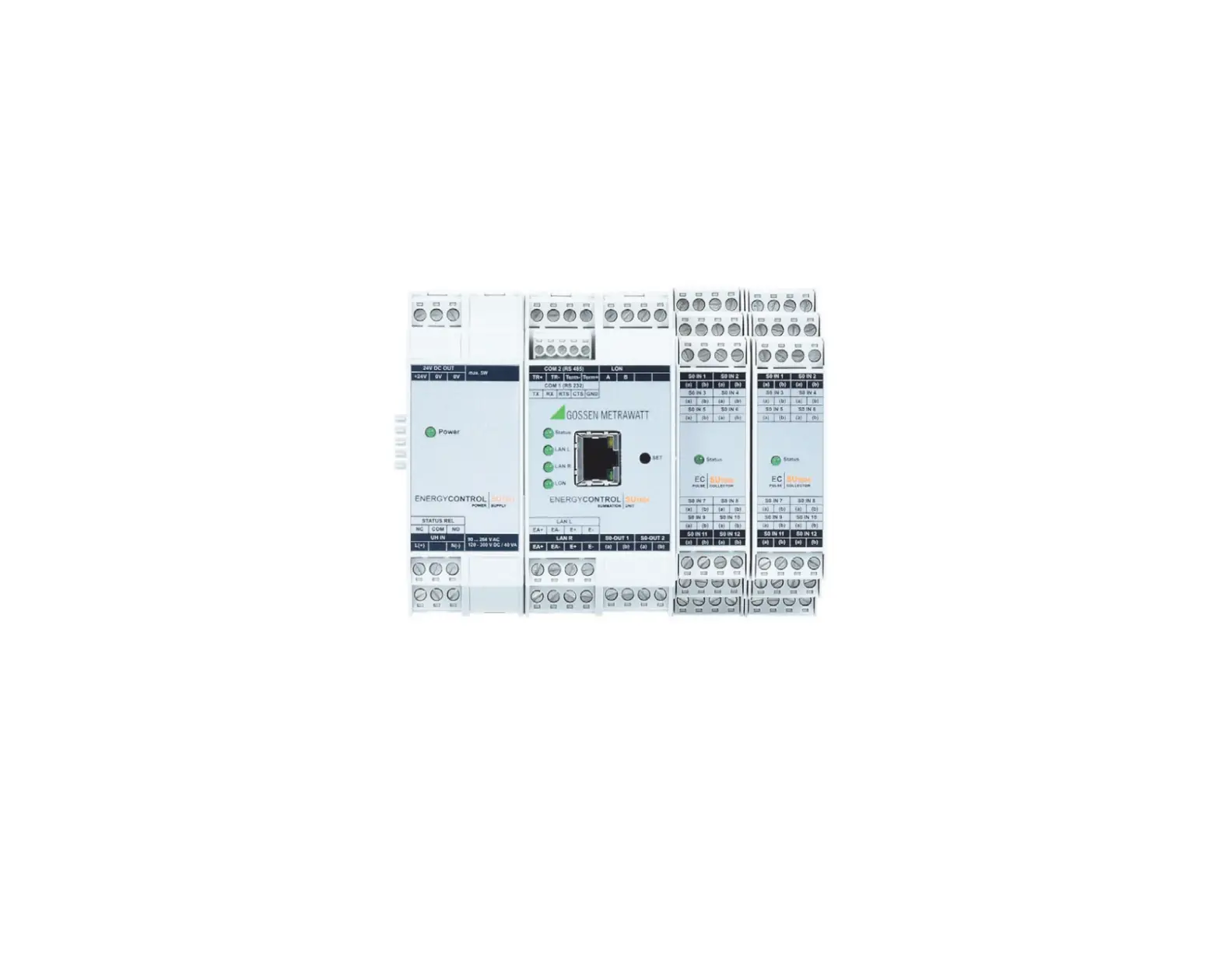
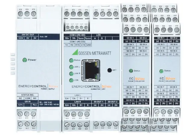
The new modular concept of the SU1604 summator permits space-saving setup of an energy control system in accordance with actual requirements. Thanks to strict software compatibility with U1600 and U1601/2/3 systems which are already in use, these can be easily replaced or expanded.
A summator can be set up using the following modules:
- U1604 basic module with the following interfaces: 1 ea. RS 232 (COM-1), 1 ea. RS 485 (COM-2), ECS LAN left + right, LON, 2 ea. S0 relay output
- U1614 power pack module with status relay for supplying power to all components via the TBUS and an additional 24 V DC output (max. 5 W) – overall output power amounts to 20 W
- U1624 S0IN12 input module with 12 S0 compatible inputs (max. 6 modules, max. 64 S0 inputs)
Connector Terminals, TBUS and Power Supply
Connector Terminals
All signals are fed to the respective module via screw terminals which can be unplugged (3, 4 or 5-pole). This assures trouble-free replacement in the event that servicing is required.
TBUS
The individual components are connected to each other via the so-called TBUS.
The TBUS is laid out as a 5-conductor system and distributes 24 V DC supply power and signals from the TBUS communications interface (RS-485) to all components. The fifth conductor is used to indicate status. One or two corresponding TBUS plug connectors are included with each module. These TBUS parts (width: 17.5 or 22.5 mm) are snapped into the DIN top-hat rail in the fully assembled state before the module is plugged on.
![]() Attention!
Attention!
During operation when auxiliary power is active, neither the U1604 basic module nor any other S0 modules may be plugged into or unplugged from the TBUS.
Please note: The U1614 power pack module with an overall width of 35 mm requires two 17.5 mm TBUS plug connectors, and all other devices require one or two of the 22.5 mm TBUS plug connectors.
Power Supply
There are two power supply options:
– Via the U1614 power pack module
![]() Attention!
Attention!
When power is supplied as auxiliary energy via the TBUS, the U1614 power pack module may not be plugged on!
– Via the external 24 V auxiliary power terminal (see photo below)
If the 24 V auxiliary power terminal is used, no status relay is available.
In order to make a status output available for this configuration, the status of the U1604 basic module can be mapped to relay 1 or 2.
The status is mapped via a so-called attribute.
Attributes are stored to non-volatile memory at the U1604 basic module and are not deleted in the event of a simple or an extended master reset.
Activating status mapping to relay 1 or 2:
STATRELMAP attribute = 1 (relay 1 or 2)
Deactivating status mapping (default):
STATRELMAP attribute = 0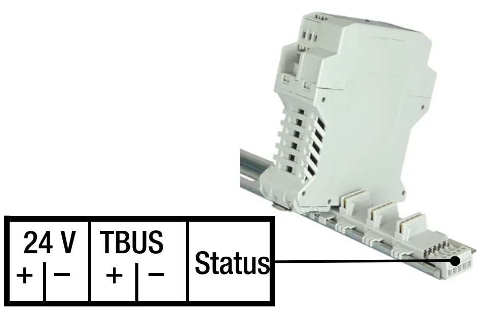
Connector pin assignments:
TBUS connector terminal PC 1719697 (Phoenix-Contact
| Hardware Feature | U1604 | U1601/2/3 | U1600 |
| Modular concept with TBUS | ✔ | — | — |
| COM-1 (RS 232) | Max. 921 kBd | Max. 115 kBd | Max. 38.4 kBd |
| COM-2 (RS 232) | — | ✔1 /✔/✔ Max. 115 kBd | (✔) 2 Max. 9600 Bd |
| COM-2 (RS 485) | Max. 921 kBd | — | — |
| ECS LAN (L+R) | Max. 375 kBd | Max. 375 kBd | Max. 125 kBd |
| LON | ✔ | ✔ | — |
| TCP/IP (10/100 Mbit/s) COM-4 COM-5 | Port 5004 Port 5005 | — | — |
| S0 compatible meter inputs with | 0 | 0 3 | 24 |
| U1624 module (12 S0 ea.) | Max. 64 | — | — |
| Analog inputs (20 mA, 10 V, S0) with | 0 | 12 / 0 / 6 | — |
| ANAIN6 module (6 ANA ea.) | — | — | — |
| Analog outputs | — | 2 / 0 / 2 | — |
| Status relay (250 V AC, 3-pole) | ✔ To U1614 | ✔ | ✔ |
| Relay (250 V AC, 3-pole) | — | 2 / 0 / 2 | 4 |
| S0 relay (semiconductor relay) | 2 | 4 / 0 / 4 | — |
| RAM Type | 4 MB 4 MRAM | 1 MB SRAM | 128 kB /512 kB 5 SRAM |
| Flash memory Type | — | 2 MB flash | 512kB EPROM |
| RTC real-time clock (with backup battery) 6 Accuracy | 5 ±5 ppm (0… +10 ppm) | ±20 ppm | ±10 ppm |
- COM-2 only available for U1601 with splitter cable
- COM-2 for U1600 with splitter cable only and only usable for DCF radio controlled clock module or for character output (printer)
- Analog inputs can be used as S0 inputs (U1601 + U1603).
- As opposed to SRAM, MRAM does not required a backup battery for data retention.
- U1600 without/with memory expansion
- Accuracy: ± 10 ppm → RTC gains (+) or loses (-) no more than roughly 0.8 s per day
COM Settings
COM1 (RS 232 full-duplex) default settings:
Baud rate: 115,200 baud (9600, 19,200, 38,400, 57,600, 76,800, 115,200, 230,400, 460,800, 921,600)
Handshake: RTS/CTS (-, RTS/CTS, XON/XOFF)
Parity Off (off, even)
Mode: ECL (OFF, ECL, DCF …)
COM2 (RS-485 half-duplex) default settings:
Baud rate: 115,200 baud (9600, 19,200, 38,400, 57,600, 76,800, 115,200, 230,400, 460,800, 921,600)
Handshake: —
Parity Off (off, even)
Mode: ECL (OFF, ECL, DCF …)
Caution: Changes to the settings may render the instrument unusable, insofar as faulty settings cannot be corrected via another correctly functioning interface.
Tip: The COM port for FTDI-based USB-RS485 converters can be permanently assigned in the device manager, and management of two or more virtual COM ports can thus be optimized.
TCP/IP
In addition to the COM-1 and COM-2 ports, ECL inputs are also available via TCP/IP. After opening one of the TCP-IP sockets from a PC, characters can be transmitted in both directions, as if connection had been established via a COM port (like a COM server).
Default IP settings and ports:
IP address: 192.168.0.50
Net mask: 255.255.255.0
Gateway: 192.168.0.1
COM-4 port: 5004 (mode = ECL)
COM-5 port: 5005 (mode = ECL)
ECSWIN settings:
If ECSwin software is used, the “W&T-COMServer” option must be selected. Setup dialog for COM-4 (default settings):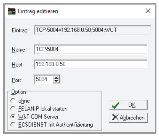
TCP/IP Settings in the ECSwin Control Panel
All adjustable IP parameters are set via ECSwin software. All IP parameters and the statuses of COM-4 and COM-5 can be checked here in the status view.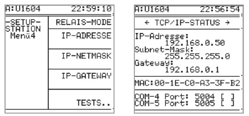
Relays and S0 Relays (S0-OUT)
The U1604 basic module makes two S0 semiconductor relays (relay/S0-OUT 1+2) available:
| U1604 | Read/Write Status | Read/Write Relay Mode |
| Relay 1 / S0-OUT 1 | REL 1 or S0REL 1 | RELM 1 |
| Relay 2 / S0-OUT 2 | REL 2 or S0REL 2 | RELM 2 |
| Relay 3 (prepared) | REL 3 | RELM 3 |
| Relay 4 (prepared) | REL 4 | RELM 4 |
| Relay 5 (prepared) | REL 5 | RELM 5 |
| Relay 6 (prepared) | REL 6 | RELM 6 |
Comparison with U1601/3 summator (relays 1+2, S0 semiconductor relays 3 … 6):
| U1601/3 | Read/Write Status | Read/Write Relay Mode |
| Relay 1 | REL 1 | RELM 1 |
| Relay 2 | REL 2 | RELM 2 |
| S0-OUT 1 | REL 3 or S0REL 1 | RELM 3 |
| S0-OUT 2 | REL 4 or S0REL 2 | RELM 4 |
| S0-OUT 3 | REL 5 or S0REL 3 | RELM 5 |
| S0-OUT 4 | REL 6 or S0REL 4 | RELM 6 |
The S0 relays are laid out as NO contacts (max. 50 V DC, 20 mA, bipolar), and assignment of the value 1 causes the S0 relay to close.
Assignment is made as follows:
REL = {0, 1} RELM = is used to set the relay’s operating mode:
0 → always off
1 → always on
2 → changeable (default)
Relays 3 through 6 have been prepared – values can be assigned and settings can be selected, but they don’t have any effect.
U1624 – 12-Way S0 Input Module S0IN12
The twelve S0 measurement inputs are implicitly assigned to energy channels 1 through 64 via the TBUS address of the S0IN12 device.
This TBUS address is set by means of a rotary encoder which can be accessed after the module has been opened. The default setting is address 0.
If two or more modules are used, they have to be addressed differently!
| TBUS Addresses | Energy Channels | Input Commands |
| 0 | 1 … 12 | 1 … 12 |
| 1 | 13 … 24 | 13 … 24 |
| 2 | 25 … 36 | 25 … 36 |
| 3 | 37 … 48 | 37 … 48 |
| 4 | 49 … 60 | 49 … 60 |
| 5 | 61 … 64 (S0 inputs 5:5 … 12 unusable) | 61 … 64 (S0 inputs 5:5 … 12 unusable) |
| 5 … 15 (F) | Reserved | |
The following applies in general: Energy_channel_number = S0IN12_input_number + (TBUS_address · 12) S0 input diagram: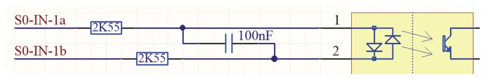
Technical Data
Binary Inputs
| U1624 – S0 Inputs, 12-Way S0IN12 | |
| Input quantity | Direct current, bipolar(square-wave pulses, S0 compatible) |
| Design | Electrically isolated |
| Input voltage | Max. 30 V |
| Input resistance | 5.1 kΩ |
Auxiliary Power Supply
| U1614 – Power Pack with Broad Range AC – DC Input | |
| Nominal range of use, AC | 90 V … 264 V |
| Frequency | 47 … 440 Hz |
| Nominal range of use, DC | 120 V … 300 V DC |
| Efficiency | 83% |
| DC output Voltage accuracy | Max. 24 V, 5 W ±2% |
| Total DC output power | Max. 24 V, 20 W (including DC out- put) |
| Power consumption U1604 (basic module) U1624 (12 ea. S0 input) | Max. 40 VA 5 W 1 W |
| Fuse | T 1.6 A/250 V AC, 300 V DC (20 mm) |
| Overvoltage category: | II |
| Protection category: | II |
| Test voltage: (alternating voltage, 1 min.) | |
| Input – housing: | 0.5 kV |
| AC auxiliary voltage input – input: | 3.0 kV |
| Status relay (U1614) – input: | 3.0 kV |
| S0 semiconductor output (U1604) – input: | 0.5 kV |
| Interfaces – input: | 0.5 kV |
| Status relay | 250 V AC, 5 A, 3-pole, AgNi 90/10 |
Memory
| MRAM – RTC | |
| MRAM Data retention | 4 MB > 20 years (data retention is independent of the RTC backup battery) |
| RTC real-time clock Follow-up time Accuracy Backup battery for RTC Service life | > 10 years 5 ±5 ppm (0 … +10 ppm) Lithium batt. 3 V/850 mA ½ AA > 10 years, battery replacement is typically unnecessary |
Outputs
| Relay Outputs | |
| 2 S0 semiconductor relays (U1604 ba- sic module) | Max. 50 V DC, 200 mA, bipolar |
| Status relay (U1614 power pack module) | 250 V AC, 5 A, 3-pole, AgNi 90/10 |
Mechanical Design
| Modular Housing Concept | |
| Width U1614 power pack module U1604 basic module U1624 S0IN12 | 35 mm 45 mm 22.5 mm |
| Height | 100 mm |
| Depth | |
| U1614 power pack module | 114 mm |
| U1604 basic module | 114 mm |
| U1624 S0IN12 | 107 mm |
| Mounting | To top-hat rail per EN 50022 / 35mm |
Return and Environmentally Sound Disposal
This instrument is subject to directive 2012/19/EC on Waste Electrical and Electronic Equipment (WEEE) and its German national equivalent implemented as the Waste Electrical and Electronic Equipment Act (ElektroG) on the marketing, return and environmentally sound disposal of electrical and electronic equipment.
The device is a category 9 product (monitoring and control instrument) in accordance with ElektroG (German Waste Electrical and Electronic Equipment Act).![]() The symbol at the left indicates that this instrument and its electronic accessories must be disposed of in accordance with applicable legal regulations, and not together with household trash. In order to dispose of the instrument, bring it to a designated collection point or contact our product support department.
The symbol at the left indicates that this instrument and its electronic accessories must be disposed of in accordance with applicable legal regulations, and not together with household trash. In order to dispose of the instrument, bring it to a designated collection point or contact our product support department.
Segregated disposal and recycling conserves resources and protects our health and the environment.
Current and further information is available on our website at http://www.gossenmetrawatt.com under the search terms “WEEE” and “environmental protection”.
Repair and Replacement Parts Service
GMC-I Service GmbH
Service Center
Beuthener Str. 41
90471 Nürnberg, Germany
Phone: +49-911-817718-0
Fax: +49-911-817718-253
e-mail: [email protected]
www.gmci-service.com
his address is only valid in Germany.
Please contact our respective representatives or subsidiaries for service in other countries.
Industrial Product Support
If required please contact:
Gossen Metrawatt GmbH
Industrial Product Support Hotline
Phone: +49-911-8602-0
Fax: +49-911-8602-340
e-mail: [email protected]