![]()
GRAM-70 RADAR LEVEL METER MIRANDA
User Manual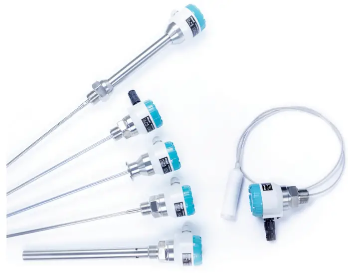
![]()
GM-70
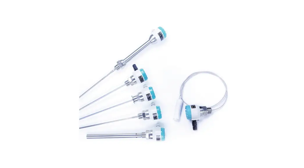
RADAR LEVEL METER,, MIRANDA”
Suited to the continuous level measurement of various liquids, mashes, bulk solids and powders.
- Radar level meter with guided wave (TDR).
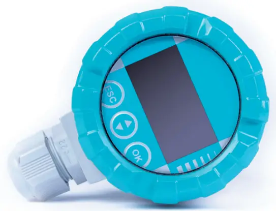
- Immediate view of the measured values on OLED or LCD display units.
- Universal use, direct mounting into containers, silos, vessels, reservoirs, etc.
- Variants with rod or rope electrode and now also all-stainless steel versions.
- Measuring range up to 40 m.
- Xi, XT versions for usage in explosive areas, or Xt, XtT versions for usage in flammable dusts areas.
- Current output (4 … 20 mA) with HART® protocol or output RS485 Modbus.

Technical specifications
| Supply voltage | GRAM–70N(T)–_ _ GRAM–70Xi(T)–_ _ GRAM–70Xt(T)–_ _ | 18 … 36 V DC 18 … 30 V DC 18 … 33 V DC |
| Output type | GRAM–70_–_ _-_-I GRAM–70_–_ _-_-M | 4 … 20 mA s HART® Hlinka RS-485 / Modbus RTU |
| Current consumption | GRAM–70_–_ _-_-I GRAM–70_–_ _-_-M | 4 … 20 mA / max. 22 mA typ. 10 mA / max. 30 mA |
| Basic measurement accuracy (for reference reflecting surface) | ± 2 mm | |
| The error of current output 2) | max. 80 μA | |
| Resolution | 0,1 mm | |
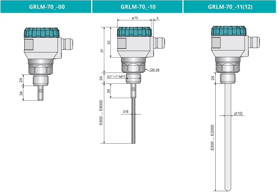
| Maximal length of measuring electrode | GRAM–70_–10, 13 GRAM–70_–11 (12) GRAM–70_–20 GRAM–70_–30 (33,34,35) GRAM–70_–32 | 8 m 2m 3m 40 m 15 m |
| Dead zone 3) | see instruction manual | |
| Adjustable measuring range (SPAN) | min. 200 mm | |
| Electrical parameters for variants Xi (XiT) – max. internal values | Ui=30 V DC; Ii=132 mA; Pi=0,99W; Ci=370 nF; Li=0,9 mH | |
| Measurement sensitivity (8 degrees) | low (1) – medium (3)- high (5) – user (1 – 8) | |
| Failure indication (echo loss) adjustable in modes | 3,75 mA, 4 mA, 20 mA, 22 mA, LAST4) | |
| Damping | 1 … 99 s | |
| Rise time | cca 60 s | |
| Leakage resistance electrode – housing | 10 kΩ | |
| Coupling capacity (housing – power) / dielectric strength | 5 nF / 500 V AC | |
| Maximal resistance of current output load Rmax for voltage – 24V DC / 22V DC / 20V DC | 270 Ω / 180 Ω / 90 Ω 5) | |
| Maximum tensile strength of the rope electrode | 1400 kg 6) | |
| Ambient temperature range 7) | -30 °C … +70 °C | |
| Process temperature range 7) | -40 °C … +200 °C | |
| Media temperature range 7) | -40 °C … +300 °C | |
| Process pressure (for temperature +85 °C) | GRAM-70N-10 (00, 20, 30, 33, 34,35, 36, 37) GRAM-70N-11 (12, 13) GRAM-70N-32 | 0 … 100 bar 0 … 20 bar 0 … 5 bar |
| Protection class | IP67 | |
- Metal circular plate 0,5 m2, type with reference tube GRLM-70_-20 water.
- This error only applies to the current output version. Data outputs (HART, MODBUS) are not affected by this error.
- Dead zone = blind zone = blocking distance at the beginning and end of the electrode.
- During an echo failure, the display shows the last measured value, and the current is held at the last valid value.
- Including 250R resistor when connected with HART.
- All ropes except the rope of GRLM-70_-32 type.
- See the instruction manual.
BASIC FEATURES AND VARIANTS
The GRLM® radar level meters are compact measuring devices consisting of two main parts a level meter (housing) and a display module (display). The electronics transmit very short electrical pulses (0.5 ns), which are linked to a one-wire transmission line (measuring electrode). Measuring electrodes can be created of a rod or rope. The pulse propagates along the electrode in the form of an electromagnetic wave toward the level surface, where it is partly reflected and the reflected component is returned to the receiving module of the electronics. The electronics measures the time of flight of electromagnetic wave and the instant distance to the surface level is calculated. Then based on the height of the level, the level meter current output 4 .. 20 mA is set with the HART communications or an industrial RS-485 line with Modbus RTU communications, and the measured value is shown on the display.
Radar level meters with guided waves are suited to the continuous level measurement of various liquid, mush, and bulk-solid materials. Level meters are resistant to changes in the atmosphere (pressure, temperature, dust, steam) and to changes in medium parameters (change in dielectric constant, conductivity)
VARIANTS
| VARIANTS | ||
| code | type of electrode | length of electrode |
| GRLM-70_-00 | Without electrode | – |
| GRLM-70_-10 | Uncoated stainless steel rod electrode | 0,5 … 8 m |
| GRLM-70_-11 | Fully coated stainless steel rod electrode (PFA) | 0,5 … 2 m |
| GRLM-70_-12 | Fully coated stainless steel rod electrode (FEP) | 0,5 … 2 m |
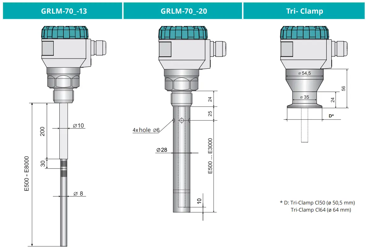
| GRLM-70_-13 | Semi-coated stainless steel rod electrode (FEP) | 0,5 … 8 m |
| GRLM-70_-20 | Uncoated stainless steel rod electrode with reference tube | 0,5 … 3 m |
| GRLM-70_-30 | Uncoated stainless steel rope electrode and weight | 1 … 40 m |
| GRLM-70_-32 | Fully coated stainless steel rope electrode (FEP) and coated weight (FEP), | 1 … 15 m |
| GRLM-70_-33 | Uncoated stainless steel rope electrode with anchorage | 1 … 40 m |
| GRLM-70_-34 | Coated stainless steel rope electrode (Polyamide) and uncoated weight | 1 … 40 m |
| GRLM-70_-35 | Coated stainless steel rope electrode (Polyamide) with uncoated anchorage | 1 … 40 m |
| GRLM-70_-36 | Non-insulated rope electrode without weights | 1 … 40 m |
| GRLM-70_-37 | Insulated rope electrode without weights (polyamide rope insulation) | 1 … 40 m |
DIMENSIONS
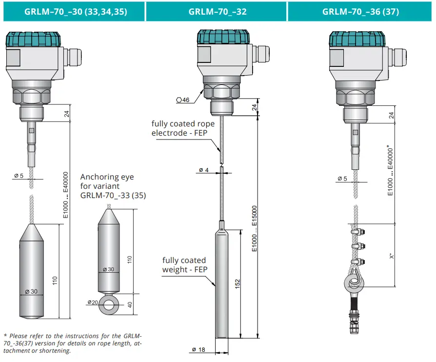
* Please refer to the instructions for the GRLM70_-36(37) version for details on rope length, attachment or shortening.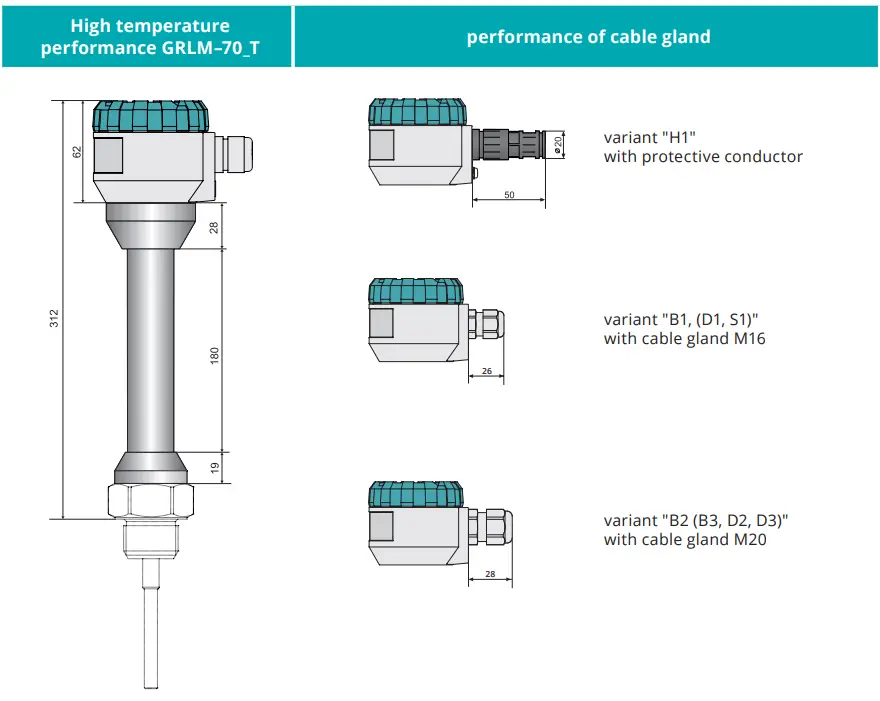
BASIC SPECIFICATIONS AND VARIANTS
TECHNICAL SPECIFICATIONS DISPLAY MODULE
| Type of display | matrix OLED, LCD 1) | |
| Resolution | 128 x 64 pixels | |
| Height of digits / Number of display digits of measured values | 9 mm / 5 digits | |
| Colour of display | OLED LCD | yellow black with white background light |
| Type of buttons | low lift membrane | |
| Ambient temperature range | OLED LCD | -30 … +70 °C -20 … +70 °C |
| Weight | 46 g | |
1) OLED- suitable for indoor and low-light applications.
LCD - suitable for outdoor applications particularly with direct sunlight.
| USED MATERIALS | ||
| unsubmerged parts of the sensor | Variants | Standard material |
| Lid | all types except GRLM-70NS (70NTS) GRLM-70NS (70NTS) | aluminum alloy with powder coating stainless steel W. Nr. 1.4301 (AISI 304) |
| Glass | all types except GRLM-70NS (70NTS) GRLM-70NS (70NTS) | polycarbonate stainless steel W. No. 1.4301 (AISI 304) |
| Body | all types except GRLM-70NS (70NTS) GRLM-70NS (70NTS) | aluminum alloy with powder coating stainless steel W. Nr. 1.4301 (AISI 304) |
| Display module | all types | plastic material POM |
| Cable gland | GRLM-70N(NT, Xi, XiT) GRLM-70Xt(XtT) GRLM-70 NS (NTS) | plastic – polyamide metal – nickel-plated brass metallic – stainless steel W. No. 1.4301 (AISI 304) |
| immersed parts of the sensor | Variants | Standard material |
| Housing | threaded head Tri-clamp | stainless steel W. Nr. 1.4404 (AISI 316 L) nickel-based alloy (W. Nr. 2.4856 / ALLOY 825) stainless steel W. Nr. 1.4404 (AISI 316 L) |
| Electrode | GRLM-70_-10 (11,12,13,20) GRLM-70_-30 (32,33,34,35,36,37) | stainless steel W. Nr. 1.4404 (AISI 316 L ) stainless steel W. Nr. 1.4401 (AISI 316 ) |
| Electrode coating | GRLM-70_-11 GRLM-70_-12, 13 GRLM-70_-32 GRLM-70_-34, 35, 37 | PFA FEP FEP PA |
| Reference tube | GRLM-70_-20 | stainless steel W. Nr. 1.4301 (AISI 304) |
| Weight | GRLM-70_-30 | stainless steel W. Nr. 1.4301 (AISI 304) |
| Weight coating | GRLM-70_-32 | FEB |
| Anchorage | GRLM-70_-33 | stainless steel W. Nr. 1.4401 (AISI 316) |
| Eye rings and clamps | GRLM-70_-36, 37 | stainless steel W. Nr. 1.4401 (AISI 316 ) |
PROCESS CONNECTION
| type | size | marking |
| Pipe thread | G 1” | G1 (G1Y) |
| Pressure thread | NPT 1″ | NPT |
| Jointless connection – Tri-Clamp | ø 50,5 mm ø 64 mm | Cl50 Cl64 |
DEVICE CLASSIFICATION
| Level meter performance | Type of electrode | Device classification and their use in the atmosphere | According to standard EN |
| GRAM–70N(T) | All types | Basic performance (high-temperature max. 200°C) | – |
| For non-explosive atmosphere | – | ||
| GRAM–70Xi(XT) | 00, 10, 11, 12, 13, 20, 30, 32, 33 | Equipment (high-temperature) protection by intrinsic safety „i“ for use in a potentially explosive atmosphere, II 1/2 G Ex ia IIB T5 Ga/Gb with intrinsically safe supply units | 60079-0, 60079-11 |
| For use in hazardous areas (explosive gas atmosphere) – electrode part zone 0 – housing with electronics zone 1 | 60079-10-1 | ||
| GRLM–70Xt(XtT) | 00, 10, 30, 33, 34, 35, 36, 37 | Equipment dust ignition protection by enclosure „t“ for use in potentially explosive atmosphere II 1/2 D Ex ta/tb IIIC T75°C…T300°C Da/Db, For use in hazardous area (explosive dust atmosphere) – electrode part zone 20 – housing with electronics zone 21 | 60079-0, 60079-31 60079-10-2 |
ELECTRICAL CONNECTION
When using the M16 gland, the level meter is connected to the follow-up (evaluation) device using a suitable cable with the outer diameter of 68 mm by means of screw terminals located under the display module. The recommended cross section of cores for the current version 2 x 0,5 ÷ 0,75 mm2 and for the version with Modbus communication 2 x 2 x 0,25 mm2 (twisted pair, shielded). In the case of the Modbus version and where it is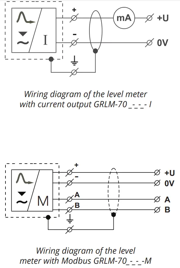 assumed that the device will not be at the end of the chain, we recommend using the M20 gland, which is suitable for 2 cables with the Ø of 5.57.5 mm. Plus pole (+U) is connected to the terminal (+), minus pole (0 V) to the terminal (-) and the shielding (only for shielded cables) to the terminal ( ). Communication wires A and B of the line RS-485 (for version,, M” – Modbus) are connected to terminals A and B.
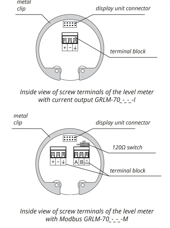
SETTING ELEMENTS
Settings are performed using 3 buttons located on the display module DM-70. All the settings are available in the menu of the level meter.
button![]()
- Set-up mode access
- Confirmation of selected item in the menu
- Move the cursor in the line
- Saving of set-up data+
button![]()
- Move-in the menu
- Change of values
button![]()
- canceling of carried out changes
- Shift one level up
Display of measured values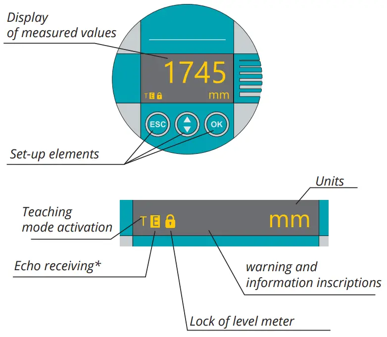
PERFORMANCE
ACCESSORIES
| 1x of seal (Achestac free), other seals (PTFE. Al. etc.) See the table in the manual for pressure resistance. | included in the price | ||
| 3 pcs stainless steel cable clamp (for the variants 36. 37) | included in the price | ||
| 1 pc stainless steel eye ring (for the variants 36. 37) | included in the price | ||
| universal converter from USB to HART | at extra cost | UHC-01 | |
| converter (Modbus) | at extra cost | URC-485 | |
| display unit | at extra cost | DM-70 | |
| fixing nuts – stainless steel G1 | at extra cost | ||
| steel welding flange | at extra cost | NN-G1ON-G1 | |
| extension cable for display | at extra cost | PK-70-1 | |
| tightening rope clamp (for the variants 36. 37) | at extra cost | ||
| mounting kit for rope anchoring (for the variants 36. 37) | at extra cost |
SAFETY, PROTECTION, COMPATIBILITY, AND EXPLOSION PROOF
The level meter is equipped with protection against fault voltage on the electrode, reverse polarity, short-term overvoltage, and current overload on output.
Protection against dangerous contact is provided by low safety voltage according to EN 33 2000-4-41 (SELV). EMC is ensured by conformity with standards EN 55011 (B), EN 61326-1, EN 61000-4-2 (A, 30kV), EN 61000-4-3 (A, 10V), EN 61000-4-4 (A, 2kV), EN 61000-4-5 (A, 2kV), EN 61000-4-6 (A, 10V).
Explosion-proof the GRLM 70Xi (XT) performance is ensured by conformity with standards EN IEC 60079-0:2018; EN 60079-11:2012, and EN 60079-26:2007. Explosion-proof of GRLM 70Xi (XT) is verified by FTZÚ AO 210 Ostrava Radvanice: FTZÚ 13 ATEX 0212X.
Explosion-proof the GRLM-70Xt (txt) performance is ensured by conformity with standards EN IEC 60079-0:2018; EN 60079-31:2014. Explosion-proof of GRLM 70Xt (txt) is verified by FTZÚ AO 210 Ostrava Radvanice: FTZÚ 15 ATEX 0207X.
A declaration of conformity was issued for this device in the wording of Act No. 90/2016 Coll., as amended. The supplied electrical equipment meets the requirements of applicable government regulations on safety and electromagnetic compatibility.
Special conditions for the safe use of the GRLM – 70Xi (XiT) variant
Level meters GRLM-70Xi (XT) are designed for connection from approved intrinsically safe circuits of power supply units (isolating repeaters) with galvanic isolation. If a device without galvanic isolation (Zener barriers) is used, it is necessary to equalize potentials between the sensor and the grounding point of the barriers.
The limit output parameters of intrinsically safe units must correspond to the limit input parameters of the level meter. When evaluating the intrinsic safety of the circuit, it is necessary to take into account the parameters of the connected cable (especially its inductance and capacity).
The electrode part of GRLM-70Xi (XT) can be placed in zone 0. Then the housing with electronic circuitry can be placed in zone 1.
Special conditions for the safe use of the GRLM-70Xt (txt) variant
Ambient temperature of the housing Ta: -30 °C up to +70 °C. For the maximum surface temperature, see Table on p. 55. When installing the variant with a transparent lid, the housing must be protected from direct daylight. The electrode part of GRLM-70Xt (txt) can be placed in zone 20. Then the housing with electronic circuitry can be placed in zone 21. The housing must be installed to avoid risk from propagation brush discharges for application in an explosive dust atmosphere.
![]() 11 04-23729418
11 04-23729418
04-23724011
[email protected]


