Zennio ZPDEZTPVT Motion Detector with Luminosity Sensor for Ceiling Mounting

INTRODUCTION
EYEZEN TP VT
EyeZen TP vT from Zennio is a device that aims at, among other functions, the detection of presence, the measurement and control of the room luminosity and the detection of occupancy within the room where it has been installed. It has been designed for ceiling or false ceiling mounting by means of the bundled accessories. The most outstanding features of EyeZen TP vT are:
- Sensor with configurable sensitivity.
- LED to indicate motion.
- Two types of lenses: black and white.
- Presence detection:
- 6 presence detection channels.
- Luminosity-dependent presence detection (optional).
- Periodic and delayed sendings (binary, scene, HVAC, percentage).
Occupancy detection:
- 1x occupancy detection channel.
- Master / slave configuration.
- Trigger upon door opening or closing.
- Periodic and delayed sendings (binary, scene, HVAC, percentage).
Luminosity measurement:
- Configurable correction factor and offset.
- Periodic sending or upon value change.
- 2 constant light control channels with configurable setpoints.
- Day / night configuration.
- 10 customisable, multi-operation logic functions.
- Heartbeat or periodical “still alive” notification.
INSTALLATION
EyeZen TP vT connects to the KNX bus through the on-board KNX connector. Once the device is provided with power from the KNX bus, both the individual address and the associated application program may be downloaded. This device does not need any additional external power since it is entirely powered through the KNX bus.
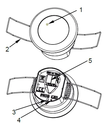
- Detection LED indicator.
- Retaining spring.
- Test/Prog. button.
- Test/Prog. LED.
- KNX connector.
The main elements of the device are described next.
- Programming button (3): a short press on this button sets the device into the programming mode, making the associated LED (4) light in red.
- Note: if this button is held while plugging the device into the KNX bus, the device will enter the safe mode. In such case, the LED will blink in red every 0.5 seconds.
- Detection notification LED (1): emits a red light flash when the sensor observes motion.
To get detailed information about the technical features of this device, as well as on the installation process and on security procedures, please refer to the corresponding Datasheet, bundled with the original packaging of the device and also available at www.zennio.com.
START-UP AND POWER LOSS
During the start-up of the device, the detection notification LED flashes red for one minute before the motion sensor is ready. Depending on the configuration, some specific actions will also be performed during the start-up. For example, the integrator can set whether the detection channels should start up enabled or disabled.
CONFIGURATION
GENERAL
After importing the corresponding database in ETS and adding the device into the topology of the desired project, the configuration process begins by entering the parameters window of the device.
ETS PARAMETERISATION
From General screen it is possible to activate/deactivate all the required functionality.

- Presence Detection [enabled]1: enables the “Presence Detector” tab in the tree on the left. For more information, see section 2.2.
- Logic Functions [enabled/disabled] enables or disables the “Logic Functions” tab in the tree on the left. For more information, see section 2.3.
- Heartbeat (Periodic Alive Notification) [enabled/disabled]: incorporates a one-bit object to the project (“[Heartbeat] Object to Send ‘1’”) that will be sent periodically with a value of “1” to notify that the device is still working (still alive).

Note: the first sending after download or bus failure takes place with a delay of up to 255 seconds, to prevent bus overload. The following sendings match the period set.
PRESENCE DETECTOR
EyeZen TP vT incorporates six independent presence detection channels, two more for constant light control and one for occupancy detection.
- Presence detection consists in sending objects to the bus whenever the device observes a moving body (or no longer observes it) in the environment of the room where it has been installed.
- Constant light control consists in sending KNX orders to the dimmer device that controls the in-room luminaries so the ambient light level remains constant even if other light sources are present.
- Occupancy detection is an algorithm that allows determining whether a particular space is under occupation no matter if the occupant moves or not (i.e., no matter if the device is detecting presence in the room or not).
It also allows setting different luminosity setpoints or object types for daytime and night time as well as activating or deactivating the motion indicator LEDs. EyeZen TP vT can also set custom sensitivity of the motion sensor and measure the luminosity of the room by making certain adjustments. This measurement will be made according to the type of lens selected. Please refer to the specific manual “Presence Detector” available in EyeZen TP vT product section at the Zennio website (www.zennio.com) for detailed information about the functionality and the configuration of the related parameters.
ETS PARAMETERISATION
In Presence Detector screen, additional to the parameters of this functionality, lens type parameter is included.
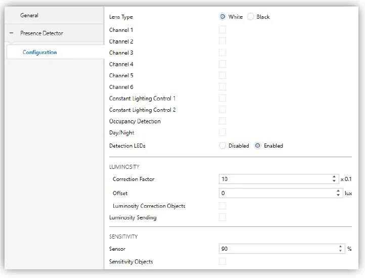
Lens Type [White / Black]. Selecting the lens type that EyeZen TP vT has installed, will allow a correct measurement of luminosity through the sensor.
LOGIC FUNCTIONS
This module makes it possible to perform numeric and binary operations to incoming values received from the KNX bus, and to send the results through other communication objects specifically enabled for this purpose. EyeZen TP vT can implement up to 10 different and independent functions, each of them entirely customisable and consisting of up to 4 consecutive operations. The execution of each function can depend on a configurable condition, which will be evaluated every time the function is triggered through specific, parameterisable communication objects. The result after executing the operations of the function can also be evaluated according to certain conditions and afterwards sent (or not) to the KNX bus, which can be done every time the function is executed, periodically or only when the result differs from the last one. Please refer to the “Logic Functions” user manual available under the EyeZen TP vT product section at the Zennio homepage (www.zennio.com) for detailed information about the functionality and the configuration of the related parameters.
ANNEX I. COMMUNICATION OBJECTS
“Functional range” shows the values that, with independence of any other values permitted by the bus according to the object size, may be of any use or have a particular meaning because of the specifications or restrictions from both the KNX standard or the application program itself.
| Number | Size | I/O | Flags | Data type (DPT) | Functional Range | Name | Function |
| 1 | 1 Bit | C – – T – | DPT_Trigger | 0/1 | [Heartbeat] Object to Send ‘1’ | Sending of ‘1’ Periodically | |
| 2 | 1 Byte | I | C – W – – | DPT_SceneNumber | 0 – 63 | Scene Input | Scene Value |
| 3 | 1 Byte | C – – T – | DPT_SceneControl | 0-63; 128-191 | Scene Output | Scene Value | |
| 4 | 2 Bytes | I/O | C R W – – | DPT_Coefficient | 0 – 80 | Correction Factor – Internal Sensor | [0, 80] x0.1 |
| 5 | 2 Bytes | I/O | C R W – – | DPT_Luminosity_Offset | -200 – 200 | Offset – Internal Sensor | [-200, 200] Luxes |
| 6 | 2 Bytes | O | C R – T – | DPT_Value_Lux | 0 – 2000 | Luminosity – Internal Sensor | Luxes |
| 10 | 1 Bit | I | C – W – – | DPT_DayNight | 0/1 | Day/Night | 0 = Day; 1 = Night |
| 1 Bit | I | C – W – – | DPT_DayNight | 0/1 | Day/Night | 0 = Night; 1 = Day | |
| 11 | 1 Bit | I | C – W – – | DPT_Enable | 0/1 | Detection LED | 0 = Disable; 1 = Enable |
| 1 Bit | I | C – W – – | DPT_Enable | 0/1 | Detection LED | 0 = Disable; 1 = Enable Only During the Day | |
| 12 | 1 Byte | O | C R – T – | DPT_Scaling | 0% – 100% | Occupancy: Output (Scaling) | 0-100% |
|
13 |
1 Byte |
O |
C R – T – |
DPT_HVACMode | 1=Comfort 2=Standby 3=Economy 4=Building Protection |
Occupancy: Output (HVAC) | Auto, Comfort, Standby, Economy, Building Protection |
| 14 | 1 Bit | O | C R – T – | DPT_Switch | 0/1 | Occupancy: Output (Binary) | Binary Value |
| 1 Bit | C – – T – | DPT_Trigger | 1 | Occupancy: Slave Output | 1 = Motion Detected | ||
| 15 | 1 Bit | I | C – W – – | DPT_Window_Door | 0/1 | Occupancy: Trigger | Binary Value to Trigger the Occupancy Detection |
| 16 | 1 Bit | I | C – W – – | DPT_Trigger | 0/1 | Occupancy: Slave Input | 0 = 1 = Detection from slave device |
| 17 | 2 Bytes | I | C – W – – | DPT_TimePeriodSec | 0 – 65535 | Occupancy: Waiting Time | 0-65535 s. |
| 18 | 2 Bytes | I | C – W – – | DPT_TimePeriodSec | 1 – 65535 | Occupancy: Listening Time | 1-65535 s. |
| 19 | 1 Bit | I | C – W – – | DPT_Enable | 0/1 | Occupancy: Lock | 0 = Unlock; 1 = Lock |
| 1 Bit | I | C – W – – | DPT_Enable | 0/1 | Occupancy: Lock | 0 = Lock; 1 = Unlock | |
| 20 | 1 Bit | O | C R – T – | DPT_Occupancy | 0/1 | Occupancy: Occupancy State | 0 = Not Occupied; 1 = Occupied |
| 21 | 1 Byte | I | C – W – – | DPT_Scaling | 0% – 100% | Sensor Sensitivity | 1-100% |
| 25, 35, 45, 55, 65, 75 | 1 Bit | I | C – W – – | DPT_Trigger | 0/1 | [Cx] External Motion Detection | 0 = 1 = Motion detected by an external sensor |
| 26, 36, 46, 56, 66, 76 | 1 Byte | O | C R – T – | DPT_Scaling | 0% – 100% | [Cx] Output (Scaling) | 0-100% |
|
27, 37, 47, 57, 67, 77 |
1 Byte |
O |
C R – T – |
DPT_HVACMode | 1=Comfort 2=Standby 3=Economy 4=Building Protection |
[Cx] Output (HVAC) | Auto, Comfort, Standby, Economy, Building Protection |
| 28, 38, 48, 58, 68, 78 | 1 Bit | O | C R – T – | DPT_Switch | 0/1 | [Cx] Output (Binary) | Binary Value |
| 29, 39, 49, 59, 69, 79 | 1 Bit | I | C – W – – | DPT_Enable | 0/1 | [Cx] Lock Status | 0 = Unlock; 1 = Lock |
| 1 Bit | I | C – W – – | DPT_Enable | 0/1 | [Cx] Lock Status | 0 = Lock; 1 = Unlock | |
| 30, 40, 50, 60, 70, 80 | 1 Bit | I | C – W – – | DPT_Switch | 0/1 | [Cx] Force State | 0 = No Detection; 1 = Detection |
| 31, 41, 51, 61, 71, 81 | 1 Bit | I | C – W – – | DPT_Switch | 0/1 | [Cx] External Switch | 0 = No Detection; 1 = Detection |
| 32, 42, 52, 62, 72, 82 | 2 Bytes | I/O | C R W – – | DPT_TimePeriodSec | 1 – 65535 | [Cx] Length of Detection | 1-65535 s. |
| 85, 101 | 1 Bit | I | C – W – – | DPT_Trigger | 0/1 | [CLCx] External Motion Detection | 0 = 1 = Motion detected by an external sensor |
| 86, 102 | 1 Bit | I | C – W – – | DPT_Enable | 0/1 | [CLCx] Lock Status | 0 = Unlock; 1 = Lock |
| 1 Bit | I | C – W – – | DPT_Enable | 0/1 | [CLCx] Lock Status | 0 = Lock; 1 = Unlock | |
| 87, 103 | 1 Bit | I | C – W – – | DPT_Switch | 0/1 | [CLCx] Force State | 0 = No Detection; 1 = Detection |
| 88, 104 | 1 Bit | I | C – W – – | DPT_Switch | 0/1 | [CLCx] External Switch | 0 = No Detection; 1 = Detection |
| 89, 105 | 2 Bytes | I | C – W – – | DPT_Value_Lux | 1 – 2000 | [CLCx] Setpoint | Setpoint Value (1-2000) |
| 2 Bytes | I | C – W – – | DPT_Value_Lux | 1 – 2000 | [CLCx] Setpoint During Day | Setpoint Value (1-2000) | |
| 90, 106 | 2 Bytes | I | C – W – – | DPT_Value_Lux | 1 – 2000 | [CLCx] Setpoint During Night | Setpoint Value (1-2000) |
| 91, 107 | 1 Byte | O | C R – T – | DPT_Scaling | 0% – 100% | [CLCx] Dimming Value | Dimming Value (%) |
| 92, 108 | 2 Bytes | I/O | C R W – – | DPT_TimePeriodSec | 1 – 65535 | [CLCx] Length of Detection | 1-65535 s. |
| 94, 110 | 1 Bit | I | C – W – – | DPT_Switch | 0/1 | [CLCx] Manual Control: On/Off (Input) | 1-Bit Control |
|
95, 111 |
4 Bit |
I |
C – W – – |
DPT_Control_Dimming | 0x0 (Stop) 0x1 (Dec. by 100%) … 0x7 (Dec. by 1%) 0x8 (Stop) 0xD (Inc. by 100%) … 0xF (Inc. by 1%) |
[CLCx] Manual Control: Relative Dimming (Input) |
4-Bit Control |
| 96, 112 | 1 Byte | I | C – W – – | DPT_Scaling | 0% – 100% | [CLCx] Manual Control: Absolute Dimming (Input) | 1-Byte Control |
| 97, 113 | 1 Bit | O | C R – T – | DPT_Switch | 0/1 | [CLCx] Manual Control: On/Off (Output) | 1-Bit Control |
|
98, 114 |
4 Bit |
O |
C R – T – |
DPT_Control_Dimming | 0x0 (Stop) 0x1 (Dec. by 100%) … 0x7 (Dec. by 1%) 0x8 (Stop) 0xD (Inc. by 100%) … 0xF (Inc. by 1%) |
[CLCx] Manual Control: Relative Dimming (Output) |
4-Bit Control |
| 99, 115 | 1 Bit | I | C – W – – | DPT_Enable | 0/1 | [CLCx] Manual Control | 0 = Disable; 1 = Enable |
| 100, 116 | 1 Bit | O | C R – T – | DPT_Enable | 0/1 | [CLCx] Manual Control (Status) | 0 = Disabled; 1 = Enabled |
| 134, 135, 136, 137, 138, 139, 140, 141, 142, 143, 144, 145, 146, 147, 148, 149, 150, 151, 152, 153, 154, 155, 156, 157, 158, 159, 160, 161, 162, 163, 164, 165 |
1 Bit |
I |
C – W – – |
DPT_Bool |
0/1 |
[LF] (1-Bit) Data Entry x |
Binary Data Entry (0/1) |
| 166, 167, 168, 169, 170, 171, 172, 173, 174, 175, 176, 177, 178, 179, 180, 181 | 1 Byte | I | C – W – – | DPT_Value_1_Ucount | 0 – 255 | [LF] (1-Byte) Data Entry x | 1-Byte Data Entry (0-255) |
| 182, 183, 184, 185, 186, 187, 188, 189, 190, 191, 192, 193, 194, 195, 196, 197 | 2 Bytes | I | C – W – – | DPT_Value_2_Ucount | 0 – 65535 | [LF] (2-Byte) Data Entry x | 2-Byte Data Entry |
| DPT_Value_2_Count | -32768 -32767 | ||||||
| 9.xxx | -671088.64 – 670433.28 | ||||||
| 198, 199, 200, 201, 202, 203, 204, 205 | 4 Bytes | I | C – W – – | DPT_Value_4_Count | -2147483648 – 2147483647 | [LF] (4-Byte) Data Entry x | 4-Byte Data Entry |
|
206, 207, 208, 209, 210, 211, 212, 213, 214, 215 | 1 Bit | O | C R – T – | DPT_Bool | 0/1 | [LF] Function x – Result | (1-Bit) Boolean |
| 1 Byte | O | C R – T – | DPT_Value_1_Ucount | 0 – 255 | [LF] Function x – Result | (1-Byte) Unsigned | |
| 2 Bytes | O | C R – T – | DPT_Value_2_Ucount | 0 – 65535 | [LF] Function x – Result | (2-Byte) Unsigned | |
| 4 Bytes | O | C R – T – | DPT_Value_4_Count | -2147483648 – 2147483647 | [LF] Function x – Result | (4-Byte) Signed | |
| 1 Byte | O | C R – T – | DPT_Scaling | 0% – 100% | [LF] Function x – Result | (1-Byte) Percentage | |
| 2 Bytes | O | C R – T – | DPT_Value_2_Count | -32768 – 32767 | [LF] Function x – Result | (2-Byte) Signed | |
| 2 Bytes | O | C R – T – | 9.xxx | -671088.64 – 670433.28 | [LF] Function x – Result | (2-Byte) Float |
Join and send us your inquiries about Zennio devices:
https://support.zennio.com
Zennio Avance y Tecnología S.L. C/ Río Jarama, 132. Nave P-8.11 45007 Toledo (Spain).
Tel. +34 925 232 002. www.zennio.com [email protected]


