![]() Instructions for installation and operation
Instructions for installation and operation
Oil-water separator
ÖWAMAT® 12 / 14 / 15 / 16 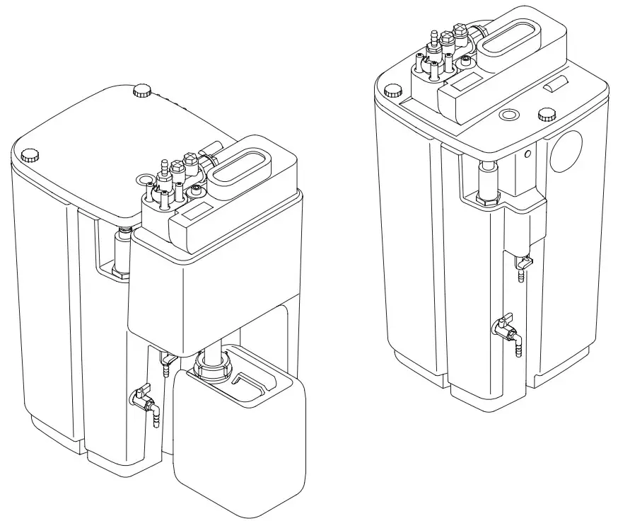 02-064
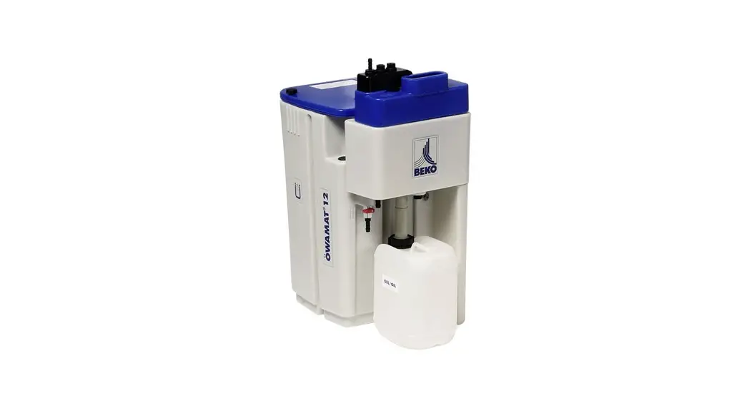
ÖWAMAT 12 Oil-Water Separator
Dear Customer,
Thank you for deciding in favour of the oil-water separator ÖWAMAT® . Please read the present instructions carefully before installing your ÖWAMAT® unit and putting it into service. The perfect functioning of the oil-water separator ÖWAMAT® – and thus reliable condensate treatment – can only be guaranteed if the recommendations and conditions stated here are adhered to.
Use as directed
The ÖWAMAT® unit is designed for the treatment of demulsifiable compressor condensates in compliance with legal requirements. Your local “lower-level water authority” needs to be notified about the operation of the oil-water separator. Media / ambient temperature:
+5 … +60 °C
– only suitable for stationary application
– not suitable for use in hazardous areas
Safety rules
![]() DANGER!
DANGER!
Compressed air!
Contact with quickly or suddenly escaping compressed air or with bursting plant components carries a risk of serious injury or death.
Only use pressure-resistant installation material!
Ensure that condensate cannot squirt or splash onto persons or objects.
Non-observance can result in injuries or damage to devices!![]() CAUTION!
CAUTION!
Oil-contaminated condensate!
Oil-contaminated condensate containssubstances that are hazardous both to health and the environment. These substances may cause irritation or damage to the skin, eyes and mucous linings. Oil-contaminated condensate must not be allowed to get into the sewer system, water bodies or the soilPlease note that the national legal limit values for indirect discharge may vary regionally.
The wastewater destined for indirect discharge must not exceed a hydrocarbon concentration of 20 mg/l.![]() CAUTION!
CAUTION!
Risk of injury
Hoses must always be fixed in such a manner that they do not make flapping movements and lead to injuries and/or damage.
Supervision
The operator must ensure through constant monitoring that the ÖWAMAT® oil-water separator is in a leaktight condition and functioning correctly.
– Check the oil-water separator for leaks regularly!
– Check the outflowing clean water every week using the reference test kit!
– Always keep a OEKOSORB® replacement filter set!
Only use original OEKOSORB® replacement filter set
Contaminated objects have to be cleaned or disposed of according to the legal regulations.
This work has to be documented in the operating manual. The operating manual and maintenance reports must be filed and presented to the responsible local authority if requested.
For the installation, the national regulations and safety instructions in force also need to be observed!
– Only transport the ÖWAMAT® unit when it is empty!
– Do not install the ÖWAMAT® outdoors!
– Protect the ÖWAMAT® against direct exposure to sunlight
– ÖWAMAT® : in the case of installation in a room where there is a danger of frost, a heating system has to be employed onl(optional)!
– Take measures to ensure that oil or untreated condensate cannot enter the sewer system in the event of damage!
– Do not fill any foreign liquid or substances into the preseparation tank / ÖWAMAT® since this may impair the filter function!
In the event of significant differences compared with the specifications of the general technical approval, e.g. the employment of non-original filters, the approval no longer covers the usability of the ÖWAMAT® product. In such cases, individual approval of the responsible local authority will be required.
The operator’s duty of care includes the following:
Installation, siting, maintenance, repair or cleaning:
These tasks have to be carried out by a specialist firm, as required by law, unless the operator himself possesses the necessary qualifications and entitlements.
To ensure trouble-free operation, observe all the points listed under maintenance:
The constituents of the compressor condensate will depend on the specific application.
It is part of the operator’s duty of care to take the necessary precautions, where appropriate.
Transport
Move the ÖWAMAT® only when empty and with suitable means of transportation.
Technical data | ||||
| OWAMAT® | 12 | 14 | 15 | 16 |
| Order reference (without pre-separation) | 4021726 (4022368) | 4021742 (4022379) | 4021758 (4022388) | 4021773 (4022400) |
| Container capacity | 30,6 1 | 61,3 1 | 115,5 1 | 228,4 1 |
| Filling volume (without pre-separation) | 22,7 1 (20,3 1) | 46,3 1 (41,5 1) | 84,3 1 (72,51) | 158,8 1 (137,2 I) |
| Condensate feed (hose) | 3 x G1/2 (di = 10 mm) 1 x G1 (di = 25 mm) | 3 x G1/2 (di = 13 mm) 1 x G1 (di = 25 mm) | ||
| Water outlet (hose) | G1/2 (di = 13 mm) | G1 (di = 25 mm) | ||
| Service valve (hose) | G % (di = 13 mm) | |||
| Oil outlet | DN 25 | DN 40 | ||
| Oil collector | 2 x 5 1 | 2 x 10 1 | 2 x 20 1 | |
| Weight empty (without pre-separation) | 13,5 kg (12 kg) | 18,5 kg (16 kg) | 36,5 kg (32 kg) | 53 kg (42 kg) |
| Min./max. temperature | +5 … +60 °C | |||
| Max. operating pressure at inlet | 16 bar *) | |||
| Prefilter | 2,5 1 | 6,7 1 | 18,5 1 | 37,2 1 |
| Main filter/cartridge volume | 5,9 1 | 11,0 1 | 20,4 1 | 40,3 1 |
| Main filter/cartridge wet weight approx. | 4,0 kg | 8,0 kg | 16,0 kg | 36,0 kg |
*) A high-pressure relief chamber should be used in the case of higher pressures (Spare parts available).
ÖWAMAT® 12 – 16
with preseparation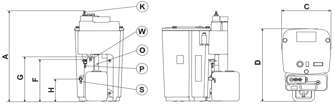
(K)= Condensate feed
(W)= Water outlet
(O)= Oil discharge
(P)= Sampling valve
(S)= Service valve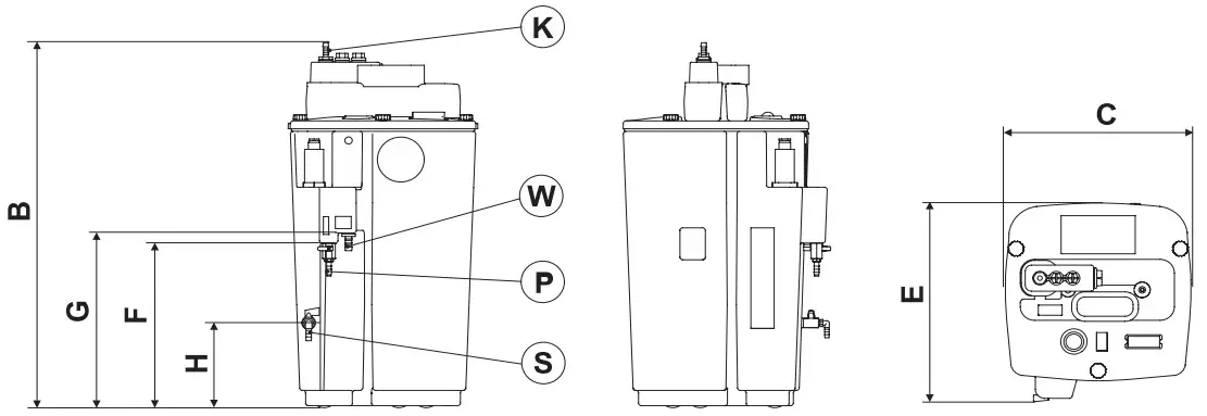
| A [mm] | B [mm] | C [mm] | D [mm] | E [mm] | F [mm] | G [mm] | H [mm] | |
| ÖWAMAT® 12 | 698 | 719 | 350 | 544 | 397 | 320 | 340 | 200 |
| ÖWAMAT® 14 | 867 | 892 | 410 | 594 | 461 | 420 | 460 | 240 |
| ÖWAMAT® 15 | 1088 | 1118 | 520 | 764 | 573 | 505 | 550 | 270 |
| ÖWAMAT® 16 | 1158 | 1193 | 650 | 939 | 702 | 535 | 580 | 200 |
The dimensions are not guaranteed product characteristics
Performance and climate data
| ÖWAMAT® | Climatic zone Zone | Compressor performance [m³/min] | |||||||||||
| Screw compressors | Piston compress., 1- and 2-stage | ||||||||||||
| Oil-free | Turbine oil | VDL oil | VCL oil | Synthetic oil | VDL oil | Synthetic oil | |||||||
| PAO | Ester | PAO | Ester | ||||||||||
| 12 | weiß | white | blanc | wit | 8,5 | 8,5 | 8,5 | 6,5 | 6,5 | 5,5 | 5,9 | 4,9 | 5,6 |
| schwarz | black | noir | zwart | 7,3 | 7,3 | 7,3 | 5,6 | 5,6 | 4,8 | 5,1 | 4,2 | 4,9 | |
| grau | grey | gris | grijs | 6,2 | 6,2 | 6,2 | 4,8 | 4,8 | 4,0 | 4,3 | 3,6 | 4,1 | |
| 14 | weiß | white | blanc | wit | 16,9 | 16,9 | 16,9 | 13,0 | 13,0 | 11,1 | 11,7 | 9,8 | 11,2 |
| schwarz | black | noir | zwart | 14,6 | 14,6 | 14,6 | 11,3 | 11,3 | 9,6 | 10,1 | 8,4 | 9,7 | |
| grau | grey | gris | grijs | 12,5 | 12,5 | 12,5 | 9,6 | 9,6 | 8,2 | 8,7 | 7,2 | 8,3 | |
| 15 | weiß | white | blanc | wit | 33,6 | 33,6 | 33,6 | 25,9 | 25,9 | 22,0 | 23,3 | 19,4 | 22,3 |
| schwarz | black | noir | zwart | 29,3 | 29,3 | 29,3 | 22,5 | 22,5 | 19,1 | 20,3 | 16,9 | 19,4 | |
| grau | grey | gris | grijs | 24,9 | 24,9 | 24,9 | 19,1 | 19,1 | 16,3 | 17,2 | 14,3 | 16,5 | |
| 16 | weiß | white | blanc | wit | 67,3 | 67,3 | 67,3 | 51,8 | 51,8 | 44,0 | 46,6 | 38,8 | 44,6 |
| schwarz | black | noir | zwart | 58,5 | 58,5 | 58,5 | 45,0 | 45,0 | 38,3 | 40,5 | 33,8 | 38,8 | |
| grau | grey | gris | grijs | 49,7 | 49,7 | 49,7 | 38,3 | 38,3 | 32,5 | 34,4 | 28,7 | 33,0 | |
Factor for filtering time with ÖWAMAT® without preseparator: 0.6
| Synthetic oil | Possible performance deviation |
| PAO | +/- 20 % |
| Ester | +/- 40 % |
BEKO recommends submitting a representative condensate sample to the company’s own laboratory to check the process suitability.
Assessment for high plant loads
| Air temperature | +30 °C | Pressure dewpoint (refrigeration dryer) | +3 °C |
| Relative humidity | 70 % | Oil load per m³ intake air | 4 mg |
| Compression pressure | 8 bar (abs) | Average filter change per annum | 2 |
| Operating hours per OEKOSORB® replacement filter set | ÖWAMAT® 12 1.500 | ÖWAMAT® 14 2.000 | ÖWAMAT® 15 3.000 | ÖWAMAT® 16 3.000 |
| Filter service life at deviating oil load of the compressed air | ||||||
| Oil load [mg/m³] | 3 | 4 | 5 | 10 | 20 | 30 |
| Filter lifetime factor | 1,12 | 1,0 | 0,88 | 0,4 | 0,2 | 0,13 |
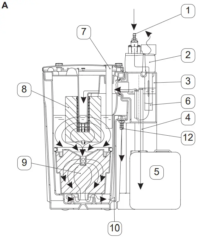
Function
The oil-contaminated condensate can be fed under pressure to the ÖWAMAT® unit 1.
The pressure is reduced in the pressure relief chamber 2 and the calmed condensate flows into the container below without creating turbulence.
Dirt particles entrained by the condensate are trapped in the dirt collector 6.
With preseparation system (A)
The free oil separates from the condensate, rises in the form of droplets and flows via the oil overflow 4 into a spillage-proof oil collector 5.
Without preseparation system (B)
After this pretreatment the condensate passes through the two-stage replacement filter.
The replacement filter comprises a prefilter 8 and a main filter 9 for binding any residual oil constituents.
The water flows out of the ÖWAMAT® oil- water separator through the water outlet 12 and can be discharged directly into the sewer system.
A sampling valve 11 * is provided so that the wastewater quality can be checked at any time.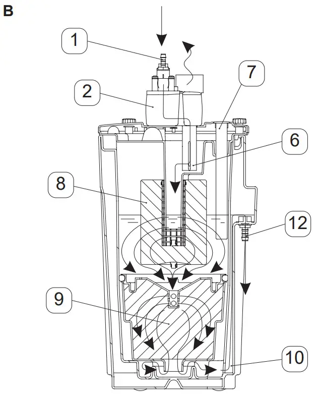
| 7. Level indicator 8. Prefilter 9. Main filter 10. Riser duct 11. Sampling valve* 12. Water outlet |
* not visible here
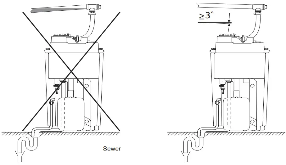
Installation
 ► NOTE
Continuous slope
The condensation collecting line must at all times have a downward slope of at least ≥3°.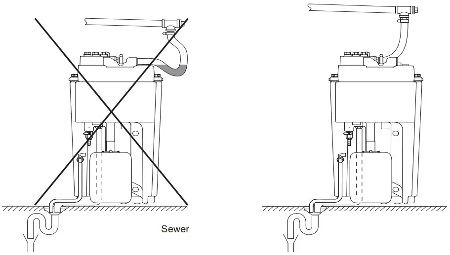 ► NOTE
Continuous slope
Avoid water pocket of the feed hose to the pressure relief chamber.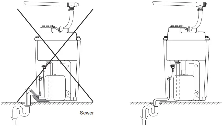 ► NOTE
Continuous slope
Avoid sagging of the hose to the waste water outlet.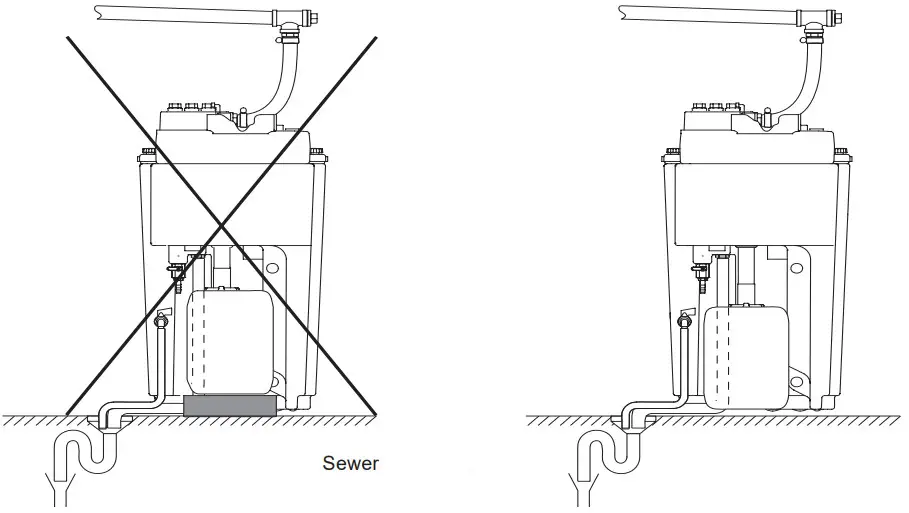 ► NOTE
Identical floor levels
Place oil collector on the same floor level so that the oil can flow into the collector. The ÖWAMAT® oil-water separator has been approved for the treatment of compressor condensates by the Institute of Construction Engineering, Berlin. In Germany, it is therefore not necessary to apply for an operating permit. Please check the relevant legal regulations in your country. You should also contact the public authorities in your area, since there may be regional variations.
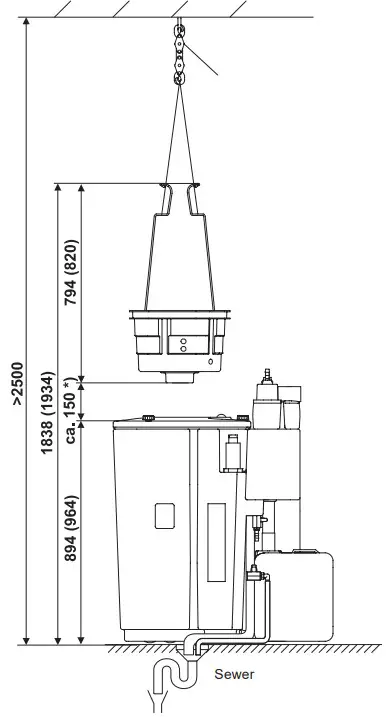
Area of installation
Sealed floor or spill basin! It is crucial to ensure that untreated condensate or oil cannot get into the sewer system in the event of damage.
The floor area must be stable and level (max. inclination ≤1°) to ensure reliable functioning of the ÖWAMAT® .
Lifting tool for OEKOSORB® replacement filters (ÖWAMAT® 15 + 16)
Should you intend to use a suitable lifting tool, the adjacent installation conditions must be observed.
The figure in brackets = ÖWAMAT® 16*) = approximate value for the required elevation height above the edge of the ÖWAMAT® Oil collector connection Place collector on the same floor level as the ÖWAMAT® to ensure oil discharge. Firmly screw the oil outlet pipe to the collector so that oil cannot leak out (not even in the event of ÖWAMAT® overloading).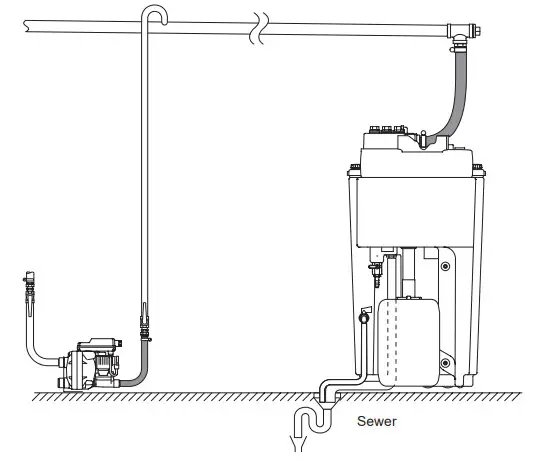
Inflow
Up to 4 feed points can be connected directly to the ÖWAMAT® .
If there are more than 4 feed points, it will be necessary to lay a collecting line.
Ring system along the wall
– nominal diameter G1 (DN 25)
– above ÖWAMAT® inlet (height above floor)
– slight slope down to the ÖWAMAT® unit (min. ≥3°)
– Feed in the condensate from the top into collecting line (swan-neck pipe bend)
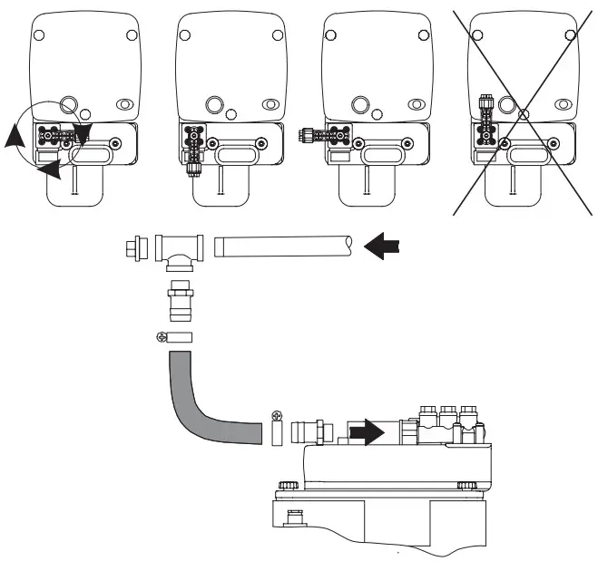
Connecting the feed line
The connecting adaptor can be turned in relation to the inflow direction:
– Remove the screws (notice O-ring and washers of connecting adaptor)
– Place connecting adaptor into position
– Replace the screws and tighten
– Connect the inlet hose to any adaptor inlet point by means of a hose clamp (use the hose connectors supplied with the unit)
– Check that the unused inlet points are tightly plugged!
► NOTE
Shut off condensate drain outlet until the oil-water separator has been installed and is ready to be put into service!
Hoses must always be fixed in such a manner that they do not make flapping movements and lead to injuries and/or damage.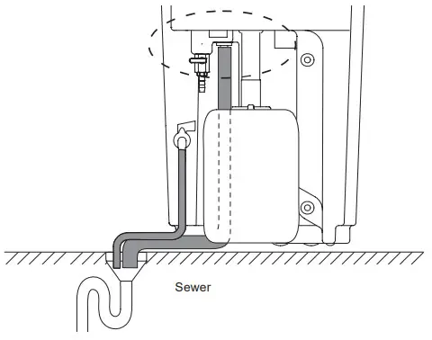
Wastewater outlet
Attach the water outlet hoses to the water outlet and to the service valve of the ÖWAMAT® and lead it to the wastewater connection with a continuous downward slope.
► NOTE
The service valve is closed during operation.
Install a siphon to seal off odours.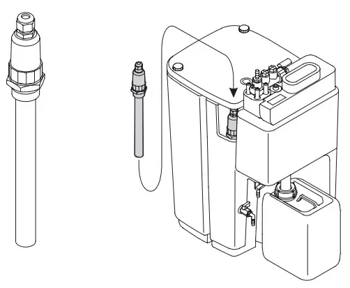 ÖWAMAT ® with heating (optional)
Please follow the instructions for installation and operation of heating systems.
If the temperature of the medium drops below approx. +5 °C, the heating will be switched on automatically.
When the setpoint temperature of +15 °C is attained, the heating will again be switched off automatically.
Built-in overheating protection limits the temperature of the heating system to a maximum of +75 °C.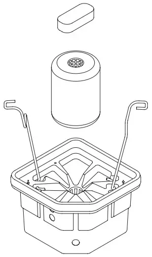
Putting into operation
OEKOSORB® replacement filter set
The ÖWAMAT® oil-water separator supplied by the manufacturer is equipped with a OEKOSORB® replacement filter set.
Check the correct seat of the OEKOSORB® replacement filter before putting the unit into service:
– Open container lid
– The handles of the main filter must be locked into place on the inner wall
– When closing the housing lid, fit the prefilter onto the guide pipe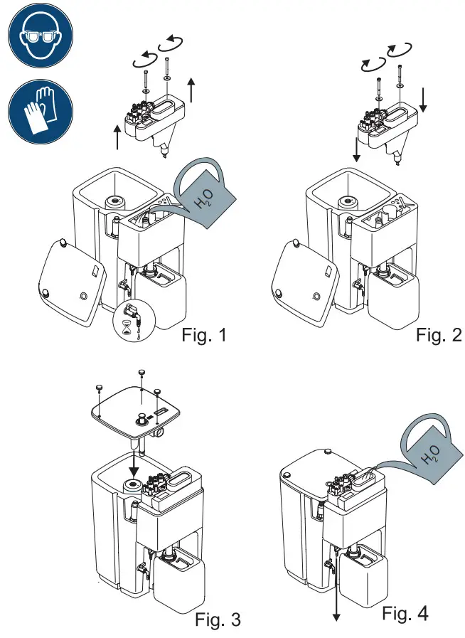 Fill ÖWAMAT® with clean water
– Fill water into the pre-separator (Fig. 1)
– Shut off water when it starts to come out at the water outlet.
– The water level will sink due to the gradual water intake of the prefilter and main filter.
– Fill up with clean water as required. (Fig. 4)
The ÖWAMAT® is ready for operation:
Compressor condensate can now flow into the ÖWAMAT® via the pressure relief chamber.
► NOTE
Open the outlet of the condensate drain!
Check all connections for leaks! The service valve is closed during operation. 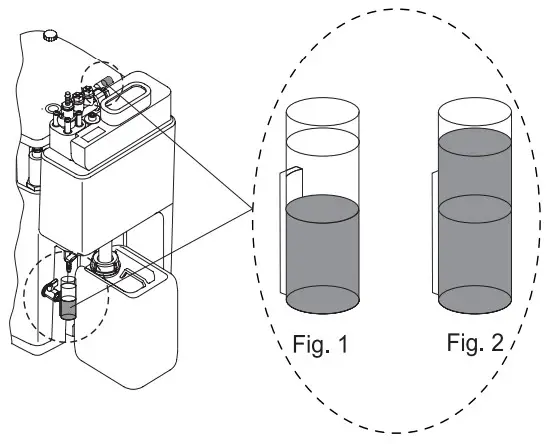
Maintenance
Weekly wastewater test
– Fill the test glass at the Sampling cock
– Compare the cloudiness with the reference jar
If the sample is clearer than the reference cloudiness
– The filter is O.K. (Fig. 1)
If the sample is cloudier than the reference cloudiness
– The filter needs to be changed! (Fig. 2)
► NOTE
Never pour any foreign liquid into the pressure relief chamber! This can impair the filter efficiency of the ÖWAMAT® . 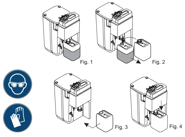
Weekly checking of oil collector
When the oil collector is ¾ full, it should be replaced with another one.
The collected oil must be disposed of as waste oil (see the chapter entitled „Disposal“).
Oil collector replacement
– Open the lid and push upwards together with discharge pipe
– Close and remove the filled oil collector
– Place an empty collector underneath the discharge pipe
– Push the discharge pipe downwards and close the lid tightly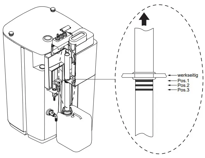
Adjusting oil overflow pipe
By adjusting the oil overflow pipe, it is possible to influence the thickness of the oil layer that is formed.
At the factory, the oil overflow pipe is pushed down into the seal to the stop.
In the vent of condensate in the oil tank, the oil overflow pipe must be repositioned. To do this, slide the oil overflow pipe upwards to position 1-3 until no more condensate is formed in the oil tank.![]() After cleaning or an oil tank change, check the oil overflow pipe and adjust it, if necessary.
After cleaning or an oil tank change, check the oil overflow pipe and adjust it, if necessary.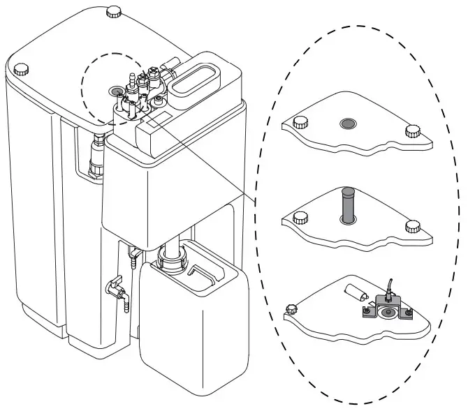
Checking of level indicator
Level indicator not visible
– Filter condition of both stages is O.K.
Red ring area visible
– Main filter stage is clogged
Replace OEKOSORB® replacement filter set!
The level indicator can be equipped with an alarm sensor as an option (see spare parts available).
The latter serves for remote monitoring and, in the event of a spilling risk, it triggers a signal when
– the accumulated amount of condensate is too high
– the filter is blocked
– the water drainage is disturbed
Weekly check of leaks
– Container
– Connections
| ÖWAMAT® | Prefilter | Main filter | Filter mat | Weight | Replacement filter set |
| [l] | [l] | [mm] | [kg] | Order Ref. | |
| 12 | 2,5 | 5,9 | 120 × 50 × 30 | 2 | 4010711 |
| 14 | 6,7 | 11,0 | 120 × 50 × 30 | 3,4 | 4010712 |
| 15 | 18,5 | 20,4 | 192 × 80 × 30 | 6 | 4010713 |
| 16 | 37,2 | 40,3 | 192 × 80 × 30 | 11,5 | 4010714 |
 ► NOTE
![]() The cartridge wet weight is significantly higher than the dry weight (e.g. ÖWAMAT® 16: 36 kg). The use of suitable lifting equipment is recommended.
The cartridge wet weight is significantly higher than the dry weight (e.g. ÖWAMAT® 16: 36 kg). The use of suitable lifting equipment is recommended.
The cartridge shall be used for one-time application once it is put into operation. As soon as the cartridge has come into contact with liquids, it must not be removed and reapplied.
Filter replacement
This is necessary when
– the water being discharged is too cloudy (see ‘Wastewater test’)
– the filter is clogged (see ‘Checking of level indicator’)
– at least 1 times a year
► NOTE
– As part of the operator’s duty of care you should always keep a spare OEKOSORB® replacement filter set.
– Only use original OEKOSORB® replacement filter sets in order to ensure operational reliability.
– In the event of significant differences compared with the specifications of the general technical approval, e.g. the employment of non-original filters, the approval no longer covers the usability of the ÖWAMAT® product.
In such cases, individual approval of the responsible local authority will be required.
– Remove plastic bag before filter installation!
Procedure
– Place new OEKOSORB® replacement filter set near the unit. Keep the PE packaging of the new set for putting in the old filters
– Shut off condensate inlet
– Open ÖWAMAT® lid
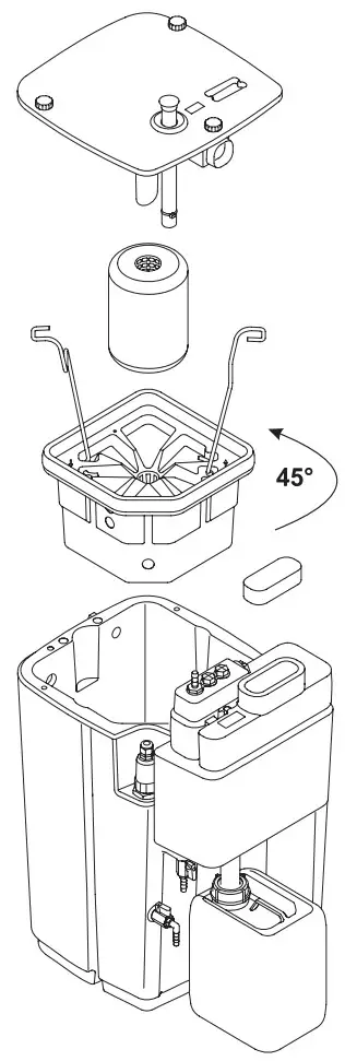
– Open the service valve and let the liquid drain off to below the level of the cartridge
– Get hold of the filter handles and slowly pull the old prefilter and main filter out of the container, turn filters counterclockwise by 45°, place on the top edge of the container and allow to drain
– Remove the handles and fit them onto the new main filter
– Put the drained prefilter/main filter into the plastic bag and ensure correct disposal (see the chapter entitled „Disposal“)
– Insert the main filter into the filter receptacle of the container using the handles, and introduce two thirds of the container in a downward direction. When encountering noticeable resistance, manually push into the final position. Snap handles into place at the side of the filter receptacle
– Insert the prefilter above the main filter and fit onto the guide pipe when closing the housing lid
– Fill ÖWAMAT® unit with clean water (see page 23).
– Open condensate inlet
– Close the service valve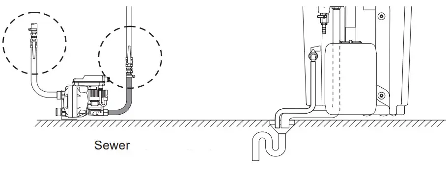
Before any maintenance
– Shut off condensate inlet if necessary switch off compressor
– If there is an in-built heating system, disconnect the device from the power supply!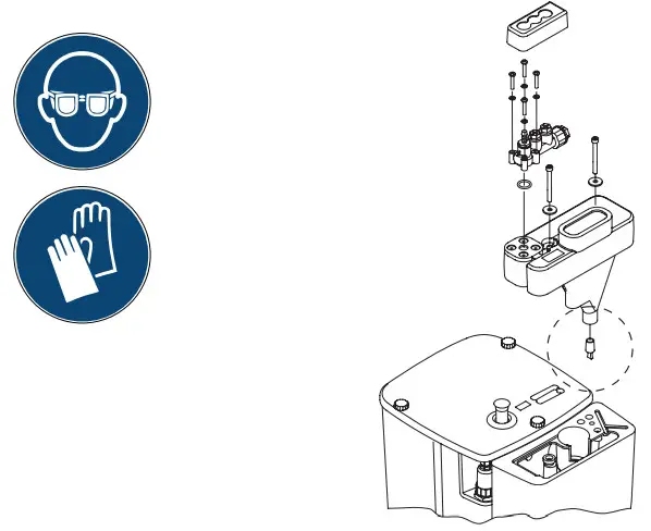
Cleaning of dirt collector
(recommended every 6 months)
– Keep a basin at hand for catching the dirt
– Detach the inlet adapter from the pressure relief chamber
– Undo the screws
– Slowly lift out the pressure relief chamber
– Pull out the plug, catch the dirt, and ensure correct disposal
– Put back the plug, reinstall the pressure relief chamber, reconnect the inlet adapter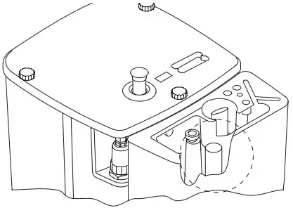
Checking of oil outlet
(recommended every 6 months)
– Remove the pressure relief chamber (as described above)
– Check oil overflow edge for dirt, clean if necessary
– Reinstall the pressure relief chamber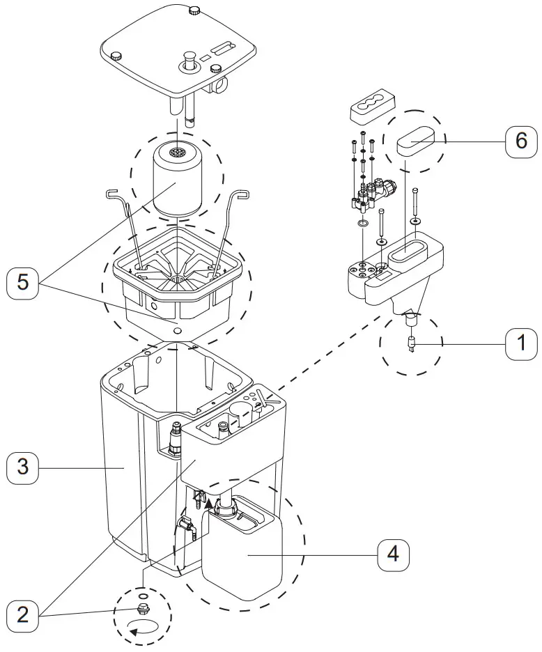 General cleaning of ÖWAMAT ®
(recommended every 12 months)
- Clean dirt collector
- Empty the preseparation tank
Clean the preseparation tank - Empty main tank
Clean main tank - Empty oil collector (page 25)
Disposal of the liquid
Observe the chapter entitled “Disposal”!
► NOTE
Do not use additional cleaners
(surfactants or solvents)! They may impair the filter efficiency.
After cleaning - Insert new prefilter and mainfilter (see page 29)
- Insert new filter mat
Fill ÖWAMAT® unit with clean water (see page 23).
After maintenance work
Open condensate inlet (if necessary switch on compressor).
If there is an in-built heating system, reconnect the power supply.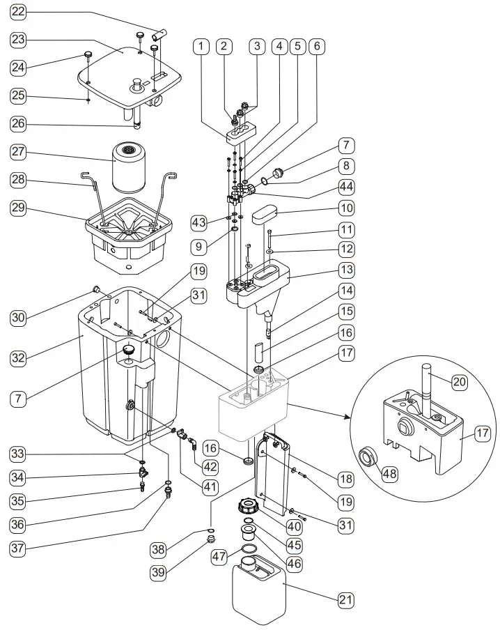
| 15 Condensate overflow 16 Gasket ÖWAMAT® 12/14: ø30/ø40 ÖWAMAT® 15/16: ø48/ø60 17 Preseparator 18 Preseparator foot 19 Cheese-head screw M6 × 30 20 Oil overflow pipe 21 Oil collector 22 Test tube 23 Lid 24 Star grip 25 Washer 26 Level indicator 27 Prefilter 28 Handle | 29 Main filter 30 Plug ø22 31 Washer 6 32 Container 33 Flat gasket 13 × 20.5 × 4 34 Sampling valve 35 Hose connector R¼“ 36 O-ring ÖWAMAT® 12: 20 × 2.2 ÖWAMAT® 14-16: 30 × 2.5 37 Hose connector ÖWAMAT® 12: G½“ ÖWAMAT® 14/15/16: G1“ 38 O-ring 20 × 2.2 39 Screw plug G½“ | 40 Screw cap incl. O-ring ÖWAMAT® 12-15: 42 × 2.5 ÖWAMAT® 16: 41.8 × 4 41 Service valve 42 Hose connector G¼“ 43 Washer 44 Connecting adaptor 45 O-Ring 30 x 2,5 46 Bushing 47 O-ring ÖWAMAT® 12-15: 42 × 2,5 ÖWAMAT® 16: 41.8 × 4 48 Formed seal |
| Spare parts available | Order ref. | |
| OEKOSORB® replacement filter set | 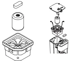 | ÖWAMAT® 12: 4010711 ÖWAMAT® 14: 4010712 ÖWAMAT® 15: 4010713 ÖWAMAT®16: 4010714 |
| Alarm sensor level indicator; normally open contact | 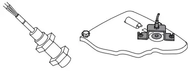 | ÖWAMAT® 12 – 16: 4013908 |
| Alarm sensor level indicator; normally closed contact | 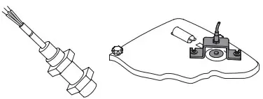 | ÖWAMAT® 12 – 16: 4013909 |
| HP-relief chamber max. 40 bar | 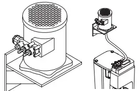 | ÖWAMAT® 12 – 16: 2801292 |
| Flow splitter max. 16 bar | 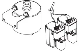 | ÖWAMAT® 12 – 16: 4003988 |
| Spill basin | 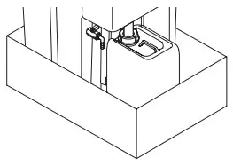 | ÖWAMAT® 12: 4047641 ÖWAMAT® 14: 4047642 ÖWAMAT® 15: 4047643 ÖWAMAT® 16: 4047644 |
| Heating | 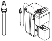 | ÖWAMAT® 12: 4001748 ÖWAMAT® 14/15: 4001750 ÖWAMAT® 16: 4001752 |
| OEKOSORB® lifting gear | 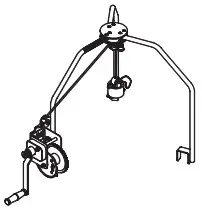 | ÖWAMAT® 15/16: 4021507 |
| Set of seal, from serial number | 12438530 | ÖWAMAT® 12/14: 4022580 ÖWAMAT® 15/16: 4022581 |
| Set of seal, to serial number | 12438529 | on request |
| Component | European waste disposal key |
| Replacement filter set: | 15 02 02 (Absorption and filter materials) |
| Oil collector: | 13 02 05 (Mineral oil) 13 02 06 (Synthetic oil) |
| Condensate: | 13 08 02 (other emulsions) |
Disposal
As regards the dismantling and disposal of the ÖWAMAT® , all of the related parts must be disposed of separately.
Container, cover, preseparator, preseparator base:
PE-LD (low-density polyethylene)
Connection adapter:
POM (polyoxymethylene/polyacetal)
Ball valve:
nickel-plated brass
Oil pipe:
PP (polypropylene)
![]() BEKO TECHNOLOGIES LTD.
BEKO TECHNOLOGIES LTD.
Unit 11-12 Moons Park
Burnt Meadow Road
North Moons Moat
Redditch, Worcs, B98 9PA
Tel. +44 1527 575 778
[email protected]
Translation of the original instructions/manual. Original instructions/manual are in German.
ow_12-16_ba_02-064_de_en_fr_nl_07_00
www.beko-technologies.com


