![]()
UM3099
User manual
How to use the StellarLINK
Introduction
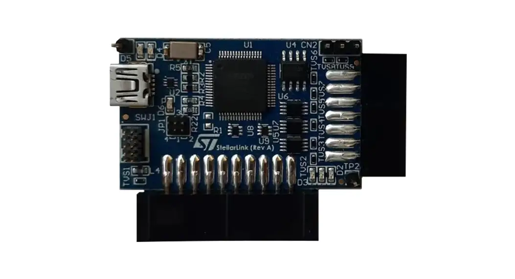
The StellarLINK is an in-circuit debugger/programmer for the Stellar microcontrollers families and for the SPC5x microcontroller families.
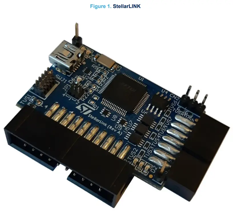

Note: picture is not contractual.
Overview
The StellarLINK adapter is a USB/JTAG debugger dongle for Stellar devices and for SPC5x devices. It is compliant with the IEEE 1149.1 JTAG protocol.
The StellarLINK adapter enables application run and debugging on Stellar boards and on SPC5x boards and it provides NVM programming (erase/program/verify).
License agreement
The packaging of this evaluation board was sealed with a seal stating, by breaking this seal, you agree to the terms and conditions of the evaluation board license agreement, the terms and conditions of which are available at https://www.st.com/resource/en/evaluation_board_terms_of_use/evaluationproductlicenseagreement.pdf.
Upon breaking the seal, you and STMicroelectronics entered into the evaluation board license agreement, a copy of which is also enclosed with the evaluation board for convenience.
Attention: This evaluation board only offers limited features for evaluating ST products. It has not been tested for use with other products and is not suitable for any safety or other commercial or consumer application. This evaluation board is otherwise provided “AS IS” and STMicroelectronics disclaims all warranties, express or implied, including the implied warranties of merchantability and fitness for a particular purpose.
Handling precautions
Please take care to handle the package content in order to prevent electrostatic discharge.
Before the EVB is used or the power is applied, please fully read the following sections on how to correctly configure the board. Failure to correctly configure the board may cause irreparable component, MCU or EVB damage.
Hardware description
4.1 Hardware features
The StellarLINK has the following features:
- USB/JTAG debugger dongle
- 5 V power supplied by a mini-USB connector
- Enables application run and debugging on Stellar devices and on SPC5x devices
- Compliant with IEEE 1149.1 JTAG protocol
- Integrates serial port connection via USB interface (virtual COM)
- Provides NVM programming (erase/program/verify)
- Connectors:
– 20-pin Arm® connector for JTAG/Main DAP interface
– 10-pin header connector for JTAG/Main DAP interface
– 14-pin header connector for JTAG interface
– 3-pin header connector for UART interface - Status LEDs to indicate target’s IO voltage, connection state, and running state
- Operating temperature range: from 0 to 50 °C
RELATED LINKS
5 Hardware configuration on page 7
4.2 Hardware dimensions
The StellarLINK has the following dimensions:
- Board dimension: 54 mm x 38 mm x 15 mm
Hardware configuration
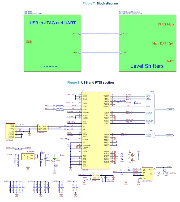
The StellarLINK is a USB adapter based on an FTDI FT2232HL interface chip.
The user EEPROM is programmed with a unique serial number.
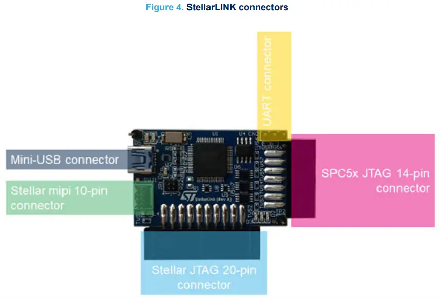
5.1 Connectors
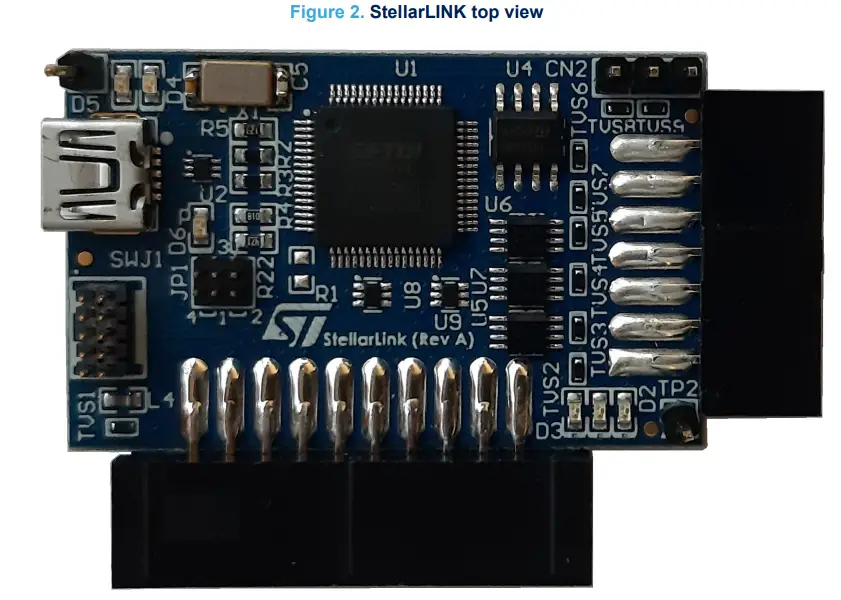
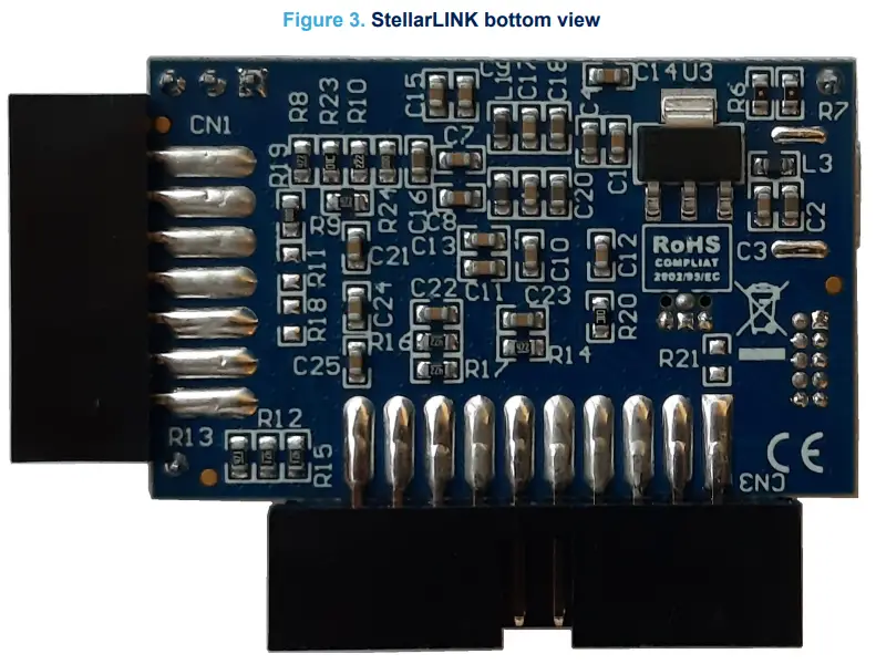
The following table describes the connectors present in the StellarLINK board.
Table 1. Connectors
| Connector | Description | Position |
| P1 | Mini-USB female connector | Top side A2 |
| SWJ1 | 10-pin header connector for JTAG/Main DAP interface | Top side A3 |
| CN1 | 14-pin header connector for JTAG interface | Top side D2-D3 |
| CN2 | 3-pin header connector for UART interface | Top side D1 |
| CN3 | 20-pin Arm connector for JTAG/Main DAP interface | Top side B4-C4 |
The following picture shows the position of the connectors available in the StellarLINK adapter.
RELATED LINKS
6 Layout overview on page 11
7 BOM on page 13
5.1.1 SWJ1
The following table describes the SWJ1 pinout.
Table 2. SWJ1 pinout
| Pin | Description |
| 1 | VIN |
| 2 | TMS |
| 3 | GND |
| 4 | TCK |
| 7 | GND |
| 5 | GND |
| 6 | TDO |
| 8 | TDI |
| 9 | GND |
| 10 | SRST |
RELATED LINKS
7 BOM on page 13
5.1.2 CN1
The following table describes the CN1 pinout.
| Pin | Description |
| 1 | TDI |
| 2 | GND |
| 3 | TDO |
| 4 | GND |
| 7 | TCK |
| 5 | GND |
| 6 | USERID 0 |
| 8 | USERID 1 |
| 9 | SRST# |
| 10 | TMS |
| 11 | VIN |
| 12 | N.C. |
| 13 | N.C. |
| 14 | TRST# |
RELATED LINKS
7 BOM on page 13
5.1.3 CN2
The following table describes the CN2 pinout.
Table 4. CN2 pinout
| Pin | Description |
| 1 | UART_RX |
| 2 | UART_TX |
| 3 | GND |
RELATED LINKS
7 BOM on page 13
5.1.4 CN3
The following table describes the CN3 pinout.
Table 5. CN3 pinout
| Pin | Description |
| 1 | VIN |
| 2 | N.C. (mounting R21 connected to VIN) |
| 3 | TRSTN |
| 4 | GND |
| 5 | TDI |
| 6 | GND |
| 7 | TMS |
| 8 | GND |
| 9 | TCK |
| 10 | GND |
| 11 | N.C. |
| 12 | GND |
| 13 | TDO |
| 14 | GND# |
| 15 | SRST# |
| 16 | GND |
| 17 | N.C. |
| 18 | GND |
| 19 | N.C. |
| 20 | GND |
RELATED LINKS
7 BOM on page 13
5.2 LEDs
The following table describes the connectors present in the StellarLINK board.
Table 6. LEDs
| Connector | Description | Position |
| D1 | Target system reset LED | Top side D4 |
| D2 | User LED | Top side D4 |
| D3 | Target’s IO voltage LED | Top side D4 |
| D4 | UART Rx LED | Top side A1 |
| D5 | UART Tx LED | Top side A1 |
| D6 | Power on LED | Top side A2 |
RELATED LINKS
6 Layout overview on page 11
7 BOM on page 13
5.3 Jumpers
The following table describes the jumpers present in the StellarLINK board.
Table 7. Jumpers
| Connector | Description | Default value | Position |
| JP1 | TRSTN target signal configuration • 1-2: Connected to a 10K ohm pullup resistor • 1-3: Connected to the TRST from FTDI • 2-3: Connected to GND | 1-3 | Top side A3 |
RELATED LINKS
6 Layout overview on page 11
7 BOM on page 13
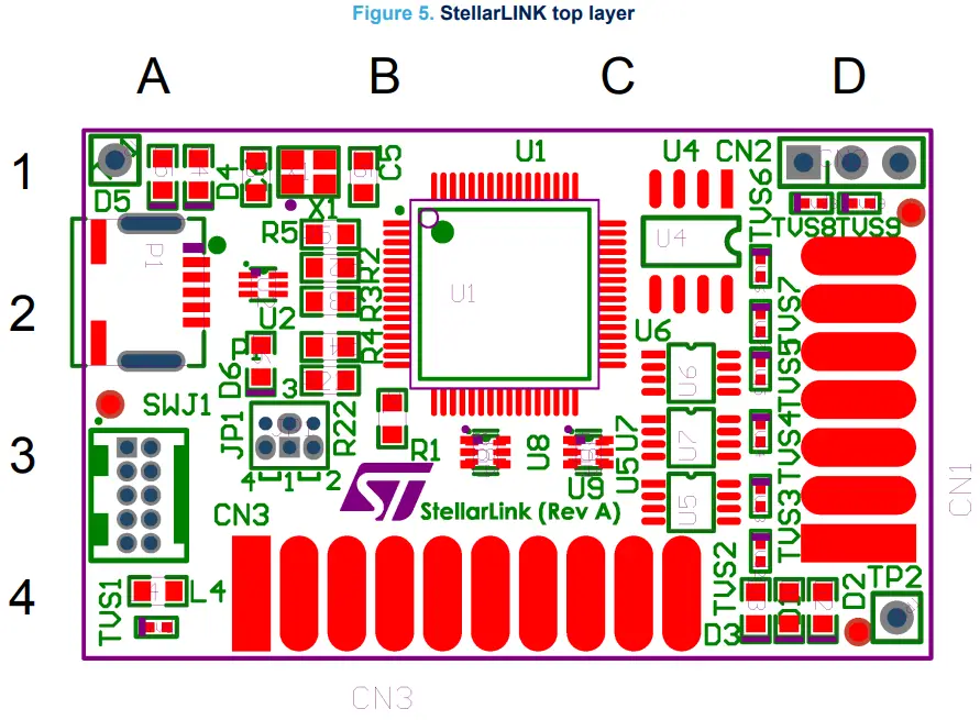
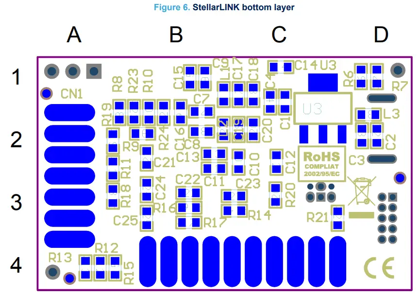
Layout overview
BOM
Table 8. BOM
| # | Item | Qty | Value | Mounting option | Description | Footprint |
| 1 | C1, C3, C7, C8, C9, C10, C11, C12, C13, C14, C15, C17, C19, C21, C22, C23, C24, C25 | 18 | 100nF | Capacitor X7R – 0603 | 0603C | |
| 2 | C2, C4 | 2 | 10μF | Capacitor X7R – 0603 | 0603C | |
| 3 | C5, C6 | 2 | 12pF | C0G ceramic multilayer capacitor | 0603C | |
| 4 | C16, C18, C20 | 3 | 4μ7 | Capacitor X7R – 0603 | 0603C | |
| 5 | CN1 | 1 | Header 7X2 female | Header, 7-Pin, dual row (6+2.5+10mm) | C_EDGE7X2_254 | |
| 6 | CN2 | 1 | Do not populate | Header connector, PCB Mount, recent, 3 contacts, pin, 0.1 pitch, pc tail terminal | STP3X1 | |
| 7 | CN3 | 1 | ARM20 | Conn Flat Male 20 pins, straight low profile | C_EDGE10X2_254 | |
| 8 | D1, D2, D3, D6 | 4 | KP-1608SGC | LED green | LED_0603 | |
| 9 | D4 | 1 | KP-1608SGC | LED green | LED_0603 | |
| 10 | D5 | 1 | KP-1608SGC | LED green | LED_0603 | |
| 11 | JP1 | 1 | Header 3×2 + jumper | Jumper 4×2.54_Closed_V | STP3X2_P50_JMP3W | |
| 12 | L1, L2, L3, L4 | 4 | 74279267 | Ferrite bead 0603 60Ohm 500mA | 0603 | |
| 13 | P1 | 1 | USB Port_B | USB-MINI_B | HRS_UX60SC-MB-5S8 | |
| 14 | R1, R11, R18, R21 | 4 | 0R | Do not populate | Resistor 0603 | 0603R |
| 15 | R2, R3 | 2 | 10R | Resistor 0603 | 0603R | |
| 16 | R4 | 1 | 1k | Resistor 0603 | 0603R | |
| 17 | R5 | 1 | 12k | Resistor 0603 | 0603R | |
| 18 | R6, R7 | 2 | Res thick film 0603 470 ohm 1% 1/4W | 0603R | ||
| 19 | R8, R9, R14, R16, R17 | 5 | 4k7 | Resistor 0603 | 0603R | |
| 20 | R10 | 1 | 2k2 | Resistor 0603 | 0603R | |
| 21 | R12, R13, R15, R22 | 4 | 470 | Resistor 0603 | 0603R | |
| 22 | R19, R24 | 2 | 0R | Resistor 0603 | 0603R |
| # | Item | Qty | Value | Mounting option | Description | Footprint |
| 23 | R20, R23 | 2 | 10k | Resistor 0603 | 0603R | |
| 24 | SWJ1 | 1 | SAM8798-ND | Debug connector 5×2 1.27mm | SAMTEC_FTSH-105-01-L-D | |
| 25 | TP1 | 1 | 90120-0921 | Do not populate | Headers | TP |
| 26 | TP2 | 1 | 90120-0921 | Do not populate | Headers | TP |
| 27 | TVS1, TVS2, TVS3, TVS4, TVS5, TVS6, TVS7, TVS8, TVS9 | 9 | 5.0V | ESD suppressor WE- VE, Vdc=5.0V | SOD882T | |
| 28 | U1 | 1 | FT2232HL | FT2232HL | TQFP50P1000X1000X100-64N | |
| 29 | U2 | 1 | USBLC6-2P6 | ESD protection | SOT666 | |
| 30 | U3 | 1 | LD1117S33TR | Low drop positive voltage regulator | SOT223 | |
| 31 | U4 | 1 | M93S46XS | 1K (x16) serial microwire bus EEPROM with Block protection | SO-8 | |
| 32 | U5, U6, U7 | 3 | SN74LVC2T45DCTR | Dual-Bit dual-supply bus transceiver | SM8 | |
| 33 | U8, U9 | 2 | SN74LVC1T45DCK | Single-Bit dual-supply bus transceiver | SOT563 | |
| 34 | U8A, U9A | 2 | SC70-6 | |||
| 35 | X1 | 1 | 12 MHz | ECS crystals 12MHz,CL 12,TOL +/-25 ppm, STAB +/-30 ppm,-40 +85 C,ESR 150O | ECS-120-12-36-AGN-TR3 |
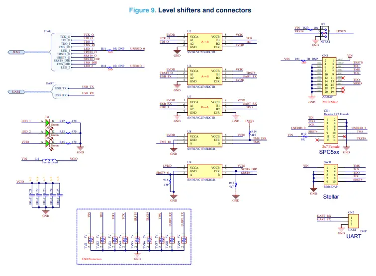
Schematics
Revision history
Table 9. Document revision history
| Date | Revision | Changes |
| 07-Nov-2022 | 1 | Initial release. |
| 20-Feb-2023 | 2 | Confidentiality level changed from restricted to public. |
IMPORTANT NOTICE – READ CAREFULLY
STMicroelectronics NV and its subsidiaries (“ST”) reserve the right to make changes, corrections, enhancements, modifications, and improvements to ST products and/or to this document at any time without notice. Purchasers should obtain the latest relevant information on ST products before placing orders. ST products are sold pursuant to ST’s terms and conditions of sale in place at the time of order acknowledgment.
Purchasers are solely responsible for the choice, selection, and use of ST products and ST assumes no liability for application assistance or the design of purchasers’ products.
No license, express or implied, to any intellectual property right is granted by ST herein.
Resale of ST products with provisions different from the information set forth herein shall void any warranty granted by ST for such product. ST and the ST logo are trademarks of ST. For additional information about ST trademarks, refer to www.st.com/trademarks. All other product or service names are the property of their respective owners.
Information in this document supersedes and replaces information previously supplied in any prior versions of this document.
© 2023 STMicroelectronics – All rights reserved


