THUNDERSTRUCK TSM2500 Series High-Efficiency Intelligent Charger
Product Overview
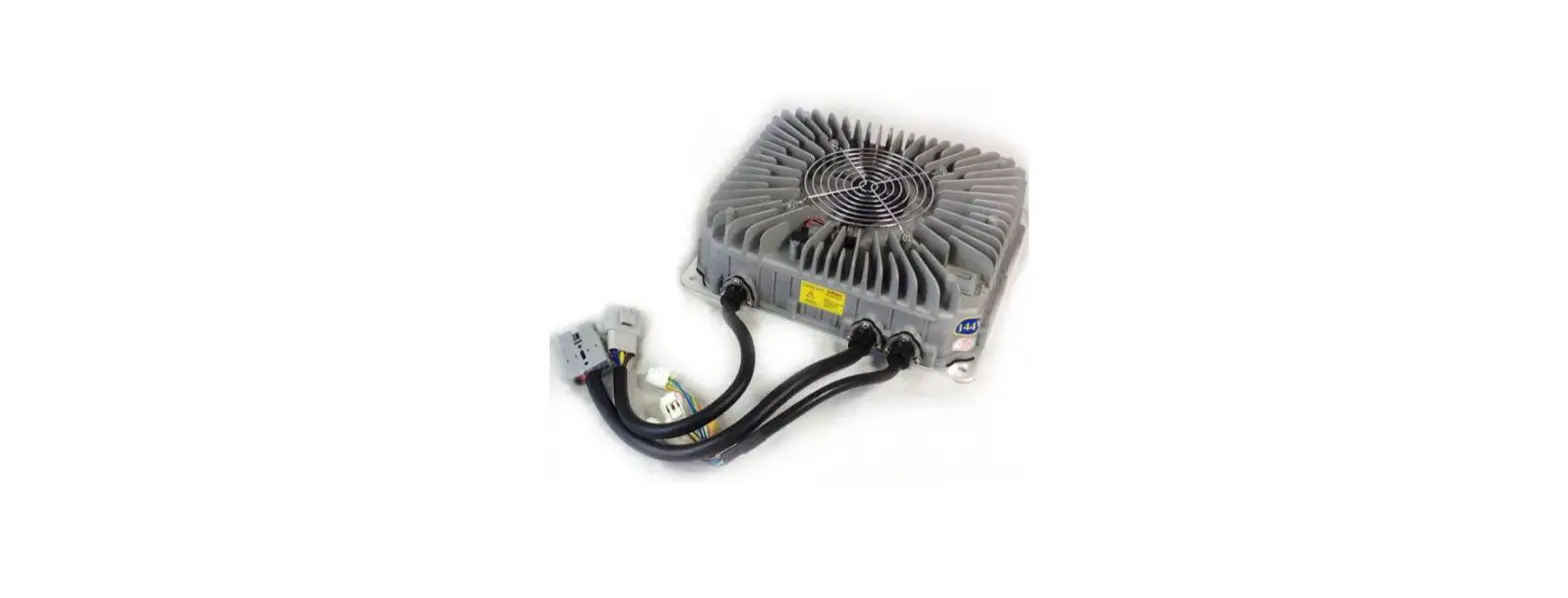
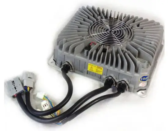
The TSM2500 series high-efficiency intelligent charger is designed to charge traction batteries of electric vehicles. This series of products adopt the most advanced technologies such as LLC resonant, active power factor correction, microcomputer measurement and control, digital adjusting, and extremely water-resistant technology. Its features include a wide input voltage range, a high input power factor that significantly reduces the input current as well as heat generated from the input cable, and a low harmonic current that reduces interference to other electric equipment. Full range soft switching is used to achieve high conversion efficiency and very little electromagnetic interference. The charger is designed according to IP66 protection grade and is highly water-resistant. It is also small in size, lightweight, quiet, beautiful, simple to install and of course easy operation and maintenance.
The charger uses microcomputer measurements and control technology, the embedded CPU can accurately detect battery voltage and charge current.
The charger has temperature compensation functions, as well as an automatic shut down after being fully charged. Reverse battery connection protection as well as output short circuit protection, AC input under-voltage protection, and overheating protection. These functions help to ensure safe and reliable use.
These are canbus-controlled chargers, which require a charge controller to initiate a charge, such as the ThunderStruck EVCC. Canbus information is available if needed for custom applications. The non-Canbus 48v charger model is designed for lead-acid batteries and provides a pre-programmed charge profile without CANbus control.
Safety
- Please do not disassemble the charger; this may cause electric shock or other injuries.
- If the charger needs to be connected to an AC power supply with extension cables, please make sure that the extension cable can withstand the maximum input current (GB 2.5mm2 copper core cable is recommended to be used), and limit the extension cable length within 10m.
- Don’t place the charger where it can get wet, this may cause damage to the charger as well as electric shock to the operator.
- The charger’s DC output plug should be connected reliably to the socket, if they are damaged or loose, please replace them immediately, otherwise it will cause overheating in the plug position, and can even cause fire.
- If the charger produces any abnormal sound or smell while on, please unplug the power immediately and contact the service department. Do not attempt to open the charger case.
- Make sure that all air vents are unobstructed to prevent charger overheating. Do not place the charger near a heat source; the charger should be left with enough space to ensure proper ventilation.
- Please disconnect the charger’s AC input power if you need to move it.
- Make sure that AC power supply voltage matches chargers’ input voltage. For inquiries, please contact your supplier or local power Supply Corporation.
- Battery voltage and the nominal voltage of the charger must be matched or it could damage both the charger and the batteries.
- To avoid damage to the charger’s cables, do not pull, twist or shake the cables or the connection terminals. If the cable is worn, please replace it immediately.
Preventing Short Circuits and Fire
- Correct use of Breakers, Sockets and Cables
- Use stranded copper cables with flame-retardant jackets. The cable core diameter must be at least 2.5mm in diameter for the AC power input.
- Prevent plugs and sockets from coming in contact with water. Note: According to statistics, 80% of electric car fires occur during charging. The main reasons for this include insufficient cable size, poor quality plugs and sockets, poor contact of plugs and sockets, poor flame-retardant sheath or shells of breakers, plugs and sockets, and uncontrolled charge cycles.
- Correct Input Connections Make sure that the charge plug and connectors are clean, undamaged and free of dirt before charging.
- Charging Environment Requirements Avoid the use of flammable materials. Charger should be mounted in a well-ventilated space. Avoid mounting/placing the charging plugs, charging cables or the charger itself on synthetic seats and other flammable objects.
- Lithium Cell Safety A lithium battery pack should have a battery management system to ensure safe charging. A battery pack with no BMS can be very dangerous. We are not responsible for damage to batteries due to using a charger with no BMS. Most prismatic lithium batteries should be contained in a manner that prevents them from swelling during charging and discharging. Consult your battery manufacturer’s recommendations for the best way to package your cells.
Regular Maintenance
- Check all connectors and J1772 Socket regularly for corrosion, discoloration or other conduction inhibitors. Poor contact may result in overheating and burning inside connectors, which could cause a fire.
- Make sure to use a charger that has a dedicated breaker and wire running to it.
- Make sure that the charger’s shell and cooling fan are free of debris and dirt.
Technical Specifications
- Rated input voltage: 220VAC 50/60Hz
- Input voltage range: 85~265VAC
(Note: When the Input voltage is lower than 185VAC, the output power will be limited to 1.5KW) - Power Factor: ≥ 0.99 @ 220VAC input, full power output;
- Total Harmonic Current: ≤ 5% @ 220VAC input, full power output;
- Nominal output voltage: 144V
- Maxim output voltage: 180V
- Rated output current: 15A
- Voltage regulation accuracy: ≤ 0.5%
- Current regulation accuracy: ≤ 2%
- Conversion efficiency: ≥ 95% @ 220VAC input, full power output
- Protection class: IP66
- Audible Noise: ≤ 40dB
- Seismic rating: Designed according to IEC60335-2-29-2004-Part.21
- Working temperature: -25~55°C (Note: models whose output power greater than 2KW
- Storage temperature: – 40~80°C
- Recognition certificates: CE SGS will ensure 2KW output at 60°C. )
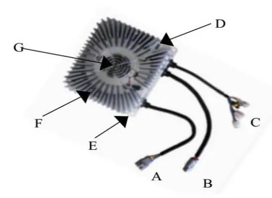
Parts List
- AC Input Cables
- DC Output Cables
- Signal Cables
- Charging Indicator E Mounting plate F Shell G – Cooling Fan and Fan Cover
LED Charge Light Information
| When… | Then… |
| Red Light Flashing | The pack is approximately < 80% Charged |
| Yellow Light Flashing | The pack is approximately > 80% Charged |
| Green Light Flashing | The pack is approximately 100% Charged |
| Flashing Yellow, Red and Green in Various Orders | Charging has recently stopped or has a Fault with Charger or Batteries. |
| Repeated flashing sequence like Red, Green, Yellow, Yellow, Yellow | Suggests a connection issue is detected (canbus or high voltage output). Check all connections. |
Input and output interface
| Input Cables | ||||||||
|
Terminal Model |
DJ7031-4.8-11 | Direction of view: form the cables to terminal. | ||||||
|
Terminal Model for matching |
DJ7031-4.8-21 | |||||||
| Needle No. | Wire Color | Wire core diameter | Description | |||||
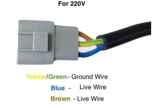
| 1# | brown | 2.5 mm2 | L——Live wire | |||||
| 2# | blue | 2.5 mm2 | N——Neutral wire | |||||
| 3# | Yellow and green | 2.5 mm2 | PE——Protective grounding wire | |||||
| Output Cables | ||||||||
|
Terminal Model |
SB50 | |||||||
| Needle No. | Wire Color | Wire core diameter | Description | |||||
| + | red | 6 mm2 | Output positive pole | |||||
| – | black | 6 mm2 | Output negative pole | |||||
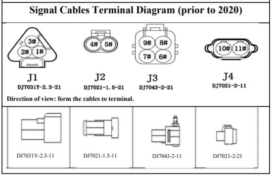
| Signal Cables | ||||||||
| Needle No. | Wire Color | Wire core diameter | Description | Needle No. | ||||
| 1# | brown |
DJ7031Y-2.3-21 |
external LED indicator interface |
DJ7031Y-2.3-11 | ||||
| 2# | Blue | |||||||
| 3# | yellow | |||||||
| 4# | purple |
DJ7021-1.5-21 | Battery Temperature sensor interface |
DJ7021-1.5-11 | ||||
| 5# | white | |||||||
| 6# | pink |
DJ7043-2-21 |
Serial communication interface |
DJ7043-2-11 | ||||
| 7# | Yellow and green | |||||||
| 8# | Blue and white | |||||||
| 9# | Green and white | |||||||
Appearance and Installation Dimensions
Do not bend the wires coming out of the charger until they have at least 50mm of space from where they enter the shell of the charger.
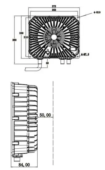
Ensure that there is a 50mm gap above the charger to allow for proper ventilation.
Connections and Wiring
Input Cables
Canbus Connection – prior to 2020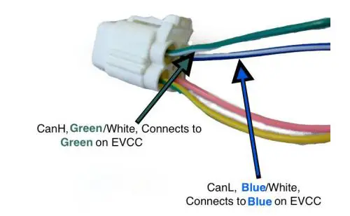
Note: The Yellow and Pink wires are not used Refer to the EVCC Manual for more details on EVCC wiring.
Canbus Connection – 2020 and later 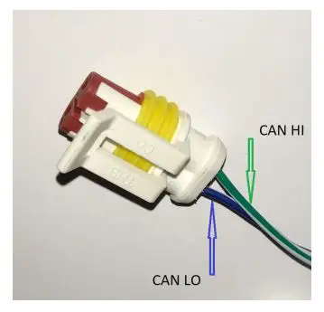
Note: If wire colors do not match, then compare connector orientation
Remote Charge Indicator Connector
Note: Remote light provided with the charger
AC Input Connection Options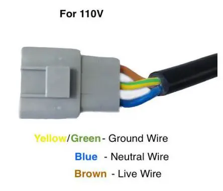
Output Cables
HV DC Output Connector 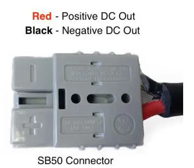
12v DC Output Connector – 2020 and Later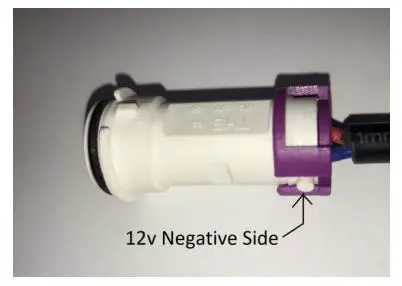
Note: During charge only, provides up to 2 amps at 12v
DC Driveaway Protection Switch Output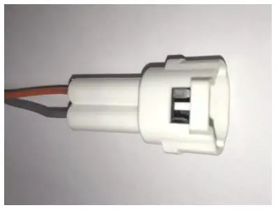
Note: EVCC can also provide driveaway protection. The above connects to a normally closed (NC) internal switch. The switch is closed when the charger is NOT plugged into AC power. This can be used to activate a 12v low current (200 ma) external relay which enables drive components only when the charger is unplugged.
FAULTS and Solutions
Please refer to the table to help resolve common charger issues. Please email ThunderStruck Motors if troubleshooting is unsuccessful. Please include all test results and measurement details.
| Fault | Analysis | Solutions |
|
No Fan or Light | Poor connection on charger AC input. AC supply circuit breaker is open or supply is off. Charger fault | Check connectors and breaker for heat damage or open circuit. Minimum supply wiring 12 ga or larger. Check J1772 Proximity connections. Contact us if fault. |
| Charging timeout | Battery circuit open or high resistance | Check DC connections at charger and entire battery circuit |
| High temperature indication with cool charger | Charger error | Please contact us |
| Charger reports incorrect voltage | Poor output connection, charger fault | Check output connections, pack connections. Contact us if fault. |
| Reaches max voltage after short charge | Poor contact between charger and battery, battery fully charged, low battery capacity | Check if the battery is damaged, battery connections are tight, the battery is fully charged |
| Low battery capacity after full charge | Wrong charge voltage, battery is aging, power circuit cable fault | Check voltage settings, replace the battery, repair cable fault |
| Low current during charge | Cables are too long or too thin Between the charger and battery, wrong current setting | Use proper cable size for length used, check charge current settings |
| Charger fan off or intermittent but light flashes | Poor input connection, dirty fan, fan faulty | Repair connections, clean fan, contact us if fan faulty |
| Arching when connecting to battery | Minor arcing is normal. Significant arcing means wrong polarity or bad charger | Check and connect the battery correctly, contact us |
| Over-Temperature Fault | Charging environment temperature is too high; cooling fan is fault; air vents are obstructed | Keep charger case away from surfaces for cooling. Ventilate charger space. Verify fan is operating. |
| Battery Overheating | Battery overcharging, wrong charger voltage, damaged or aging battery | Check charge settings, Test and replace battery |


