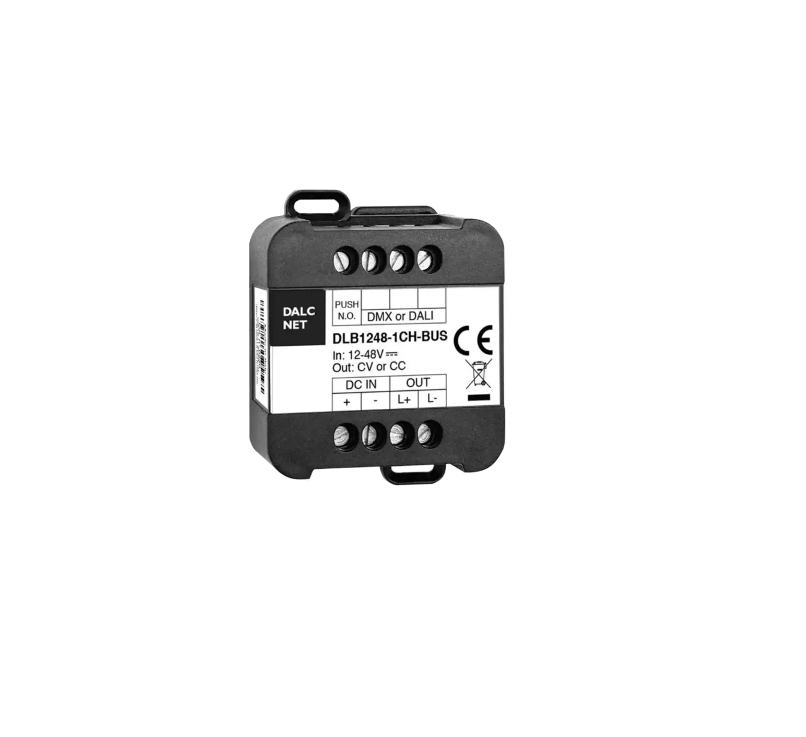
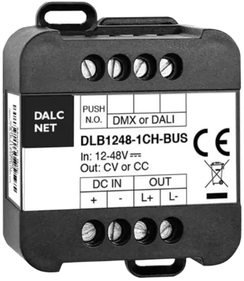
DALCNET DLB1248 Single Channel
FEATURES
- BUS+FADER+DIMMER+DRIVER
- DC Input: 12-24-48 Vdc
- Remote command options:
– DMX512+RDM
– DALI · Local command options:
– Normally Open push-button - Adjusting the brightness of white light
- Current outputs or voltage outputs for R-L-C loads
- Typical efficiency > 95%
- Adjusting the brightness up to completed off
- Soft start and soft stop
- Optimized output curve
- Extended temperature range
- 100% Functional test 5 Years warranty
For the whole and update Device Manual refer to producer’s website: http://www.dalcnet.com
➢ CONSTANT CURRENT VARIANTSS
Application: Dimmer
| CODE | Input voltage | Output | Channels | Commands |
| DLB1248-1CC350-DMX | 12-48V DC | 1 x 350mA | 1 | DMX – 1 N.O. push button |
| DLB1248-1CC350-DALI | 12-48V DC | 1 x 350mA | 1 | DALI – 1 N.O. push button |
| DLB1248-1CC500-DMX | 12-48V DC | 1 x 500mA | 1 | DMX – 1 N.O. push button |
| DLB1248-1CC500-DALI | 12-48V DC | 1 x 500mA | 1 | DALI – 1 N.O. push button |
| DLB1248-1CC700-DMX | 12-48V DC | 1 x 700mA | 1 | DMX – 1 N.O. push button |
| DLB1248-1CC700-DALI | 12-48V DC | 1 x 700mA | 1 | DALI – 1 N.O. push button |
| DLB1248-1CC950-DMX | 12-48V DC | 1 x 950mA | 1 | DMX – 1 N.O. push button |
| DLB1248-1CC950-DALI | 12-48V DC | 1 x 950mA | 1 | DALI – 1 N.O. push button |
| Any current value in range from 150mA to 950mA is available on demand. | ||||
➢ CONSTANT VOLTAGE VARIANTS
Application: Dimmer
| CODE | Input voltage | Output | Channels | Commands |
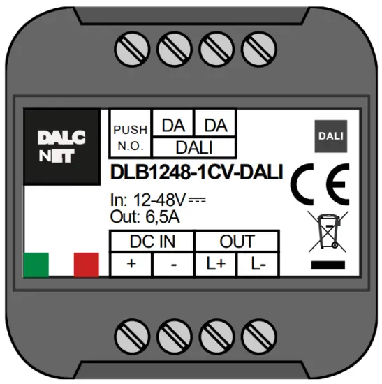
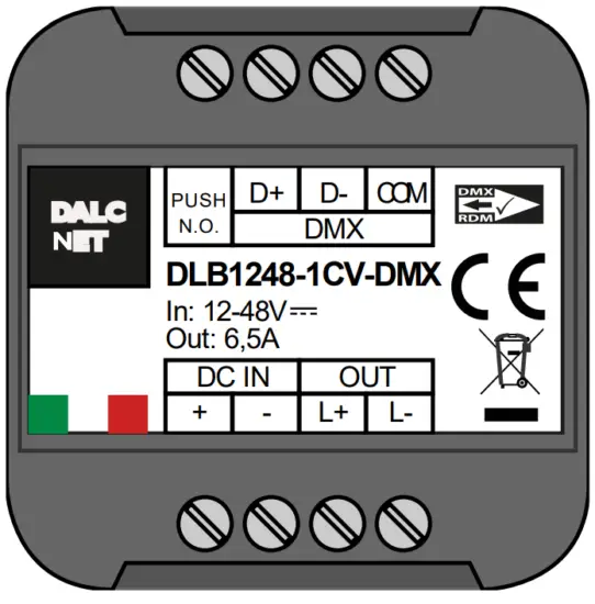
| DLB1248-1CV-DMX | 12-48V DC | 1 x 6,5A max | 1 | DMX – 1 N.O. push button |
| DLB1248-1CV-DALI | 12-48V DC | 1 x 6,5A max | 1 | DALI – 1 N.O. push button |
➢ PROTECTIONS
| CC | CV | ||
| OTP | Over temperature protections1 | ✓ | ✓ |
| OVP | Over voltage protections2 | ✓ | ✓ |
| UVP | Under voltage protection7 | ✓ | ✓ |
| RVP | Reverse polarity protection7 | ✓ | ✓ |
| IFP | Input fuse protection7 | ✓ | ✓ |
| SCP | Short circuit protection | ✗ | ✓ |
| OCP | Open circuit protection | ✓ | ✗ |
| CLP | Current limit protection | ✓ | ✓ |
| 1 Thermal Protection on the output channel in case of high temperature. The termal intervention is detected by transistor (>150°C) or by constant current LED driver regulation in current variant (>150°C). 2 Only control logic protection |
➢ REFERENCE STANDARDS
| EN 61347-1 | Lamp controlgear – Part 1: General and safety requirements |
| EN 55015 | Limits and methods of measurement of radio disturbance characteristics of electrical lighting and similar equipment |
| EN 61547 | Equipment for general lighting purposes – EMC immunity requirements |
| EN 50581 | Technical documentation for the assessment of electrical and electronic products with respect to the restriction of hazardous substances |
| IEC/EN 62386-101 | Digital addressable lighting interface – Part 101: General requirements – System |
| IEC/EN 62386-102 | Digital addressable lighting interface – Part 102: General requirements – Control gear |
| IEC/EN 62386-207 | Digital addressable lighting interface – Part 207: Particular requirements for control gear – LED modules (device type 6) |
| IEC 60929-E.2.1 | Control interface for controllable ballasts – control by d.c. voltage – functional specification |
| ANSI E 1.3 | Entertainment Technology – Lighting Control Systems – 0 to 10V Analog Control Specification |
| ANSI E1.11 | Entertainment Technology – USITT DMX512-A – Asynchronous Serial Digital Data Transmission Standard for Controlling Lighting Equipment and Accessories |
| ANSI E1.20 | Entertainment Technology-RDM-Remote Device Management over USITT DMX512 Networks |
| – | MODBUS APPLICATION PROTOCOL SPECIFICATION V1.1b |
➢ TECHNICAL SPECIFICATIONS
Variants | ||||||
Constant current | Constant voltage | |||||
| 350mA | 500mA | 700mA | 950mA | |||
| Supply voltage | min: 10,8 Vdc .. max: 52,8 Vdc | |||||
| Output voltage | min: Vin/4 max: Vin-0.9V | = Vin | ||||
| Input current | max 0,53A | max 0,5A | max 0,7A | max 0,95A | max 6,5A | |
| Output current | 350 mA | 500 mA | 700 mA | 950 mA | 6,5A @40°C | |
| Absorbed nominal power3 | @12V | 4.2 W | 6 W | 8.4 W | 11.4 W | 78 W |
| @24V | 8.4 W | 12 W | 16.8 W | 22.8 W | 156 W | |
| @48V | 16.8 W | 24 W | 33.6 W | 45.6 W | 312 W | |
| Power loss in standby mode | <500mW | |||||
| Type of Load | R-L-C | |||||
| Thermal shutdown | 150 °C | |||||
| D-PWM dimming frequency | 250Hz | |||||
| D-PWM resolution | 16 bit | |||||
| D-PWM range | 0,1 – 100 % | |||||
| Storage temperature | min: -40 max: +60 °C | |||||
| Ambient temperature | min: -10 max: +40 °C | |||||
| Wring | 2.5mm² solid – 1.5mm² stranded – 30/12 AWG | |||||
| Wire preparation length | 5,5 – 6,5 mm | |||||
| Protection grade | IP20 | |||||
| Casing material | Plastic | |||||
| Packaging unit (pieces/unit) | Single Carton Box 1pz | |||||
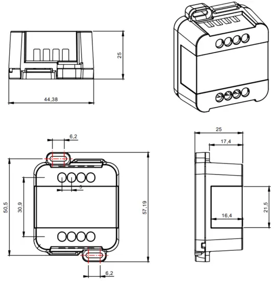
| Mechanical dimensions | 45 x 58 x 25 mm | |||||
| Package dimensions | 56 x 68 x 35 mm | |||||
| Weight | 40g | |||||
➢ INSTALLATION
As shown below do the following steps to install the product:
1) connect the power supply (12-48 V) to the device terminals DC IN
2) connect the N.O. Push button and / or the BUS in the correct terminals of the device
3) connect the LED output terminals OUT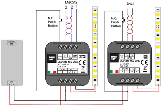
➢ MECHANICAL DIMENSION:
➢ TECHNICAL NOTES
Installation:
- Installation and maintenance must be performed only by qualified personnel in compliance with current regulations.
- The product must be installed inside an electrical panel protected against overvoltages.
- The product must be installed in a vertical or horizontal position with the cover / label upwards or vertically; Other positions arenot permitted. It is not permitted to bottom-up position (with the cover / label down).
- Keep separated the circuits at 230V (LV) and the circuits not SELV from circuits to low voltage (SELV) and from any connection with this product. It is absolutely forbidden to connect, for any reason whatsoever, directly or indirectly, the 230V mains voltage to the bus or to other parts of the circuit.
Power supply:
- For the power supply use only a SELV power supplies with limited current, short circuit protection and the power must be dimensioned correctly. In case of using power supply with ground terminals, all points of the protective earth (PE = Protection Earth) must be connected to a valid and certified protection earth.
- The connection cables between the power source “low voltage” and the product must be dimensioned correctly and they should be isolated from every wiring or parts at voltage not SELV. Use double insulated cables.
- Dimension the power supply for the load connected to the device. If the power supply is oversized compared with the maximum absorbed current, insert a protection against over-current between the power supply and the device.
- For the constant current output, the voltage of LED module (Vf) must be less of 5V at the voltage of power supply.
Command:
- The length of the connection cables between the local commands (N.O. Push button or other) and the product must be less than10m; the cables must be dimensioned correctly and they should be isolated from every wiring or parts at voltage not SELV. Use double insulated shielded and twisted cables.
- The length and type of the connection cables at the BUS (DMX512, Modbus, DALI or other) use cables as per specification of the respective protocols and regulations and they should be isolated from every wiring or parts at voltage not SELV. Use double insulated shielded and twisted cables.
- All the product and the control signal connect at the bus (DMX512, Modbus, DALI or other) and at the local command (N.O. Push Button or other) must be SELV (the devices connected must be SELV or supply a SELV signal)
Outputs:
- The length of the connection cables between the product and the LED module must be less than 10m; the cables must be dimensioned correctly and they should be isolated from every wiring or parts at voltage not SELV. Is preferable to use shielded and twisted cables.
➢ LOCAL COMMAND
PUSH DIMMER FEATURE
The intensity and the status change (ON/OFF) are controlled by the N.O. push button
| Button | Intensity |
| Click Double click Long pressure (>1s) from OFF Long pressure (>1s) from ON | On/Off Maximum intensity Turn on at 1% (Nightly Time), then the dimmer up/down Dimmer up/down |
➢ DALI BUS SETUP
In DALI BUS SETUP all the leds are controlled by an external DALI controller
FEATURES
• BUS DALI
REFERENCE STANDARDS
| IEC/EN 62386-101 | Digital addressable lighting interface – Part 101: General requirements – System |
| IEC/EN 62386-102 | Digital addressable lighting interface – Part 102: General requirements – Control gear |
| IEC/EN 62386-207 | Digital addressable lighting interface – Part 207: Particular requirements for control gear – LED modules (device type 6) |
RELATIONS WITH LOCAL COMMANDS
At first power-up in case of absence of connection to the BUS, local control is active.
When the BUS is detected, the control passes to the BUS.
In the absence of signal the control passes to local commands in the event of the button pressure.
The control mode is memorized on a non-volatile memory.
ADDRESSING
| Simplified method (One ballast connected at time) | ✓ |
| Random Address Allocation | ✓ |
CHANEL MAP
The intensity and the status (ON/OFF) is controlled by a DALI controller.
| Address | Function | Value |
| 0 | Dimmer | Intensity [0.254] |
➢ COMMANDS
STANDARD COMMANDS | |
| DIRECT ARC POWER | ✓ |
| OFF | ✓ |
| UP | ✓ |
| DOWN | ✓ |
| STEP UP | ✓ |
| STEP DOWN | ✓ |
| RECALL MAX LEVEL | ✓ |
| RECALL MIN LEVEL | ✓ |
| STEP DOWN AND OFF | ✓ |
| ON AND STEP UP | ✓ |
| GOTO SCENE (0 to 15) | ✓ |
| RESET | ✓ |
| STORE ACTUAL LEVEL IN THE DTR | ✓ |
| STORE THE DTR AS MAX LEVEL | ✓ |
| STORE THE DTR AS MIN LEVEL | ✓ |
| STORE THE DTR AS SYSTEM FAILURE LEVEL | ✓ |
| STORE THE DTR AS POWER ON LEVEL | ✓ |
| STORE THE DTR AS FADE TIME | ✓ |
| STORE THE DTR AS FADE RATE | ✓ |
| STORE THE DTR AS SCENE (0 to 15) | ✓ |
| REMOVE FROM SCENE (0 to 15) | ✓ |
| ADD TO GROUP (0 to 15) | ✓ |
| REMOVE FROM GROUP (0 to 15) | ✓ |
| STORE DTR AS SHORT ADRESS | ✓ |
| ENABLE WRITE MEMORY | ✗ |
| QUERY STATUS | 4 |
| QUERY BALLAST | ✓ |
| QUERY LAMP FAILURE | 4 |
| QUERY LAMP POWER ON | ✓ |
| QUERY LIMIT ERROR | ✓ |
| QUERY RESET STATE | ✓ |
| QUERY MISSING SHORT ADDRESS | ✓ |
| QUERY VERSION NUMBER | ✓ |
| QUERY CONTENT DTR | ✓ |
| QUERY DEVICE TYPE | 5 |
| QUERY PHYSICAL MINIMUM LEVEL | ✓ |
| QUERY POWER FAILURE | ✓ |
| QUERY CONTENT DTR1 | ✓ |
| QUERY CONTENT DTR2 | ✓ |
| QUERY ACTUAL LEVEL | ✓ |
| QUERY MAX LEVEL | ✓ |
| QUERY MIN LEVEL | ✓ |
| QUERY SYSTEM FAILURE LEVEL | ✓ |
| QUERY FADE TIME / FADE RATE | ✓ |
| QUERY SCENE LEVEL (0 to 15) | ✓ |
| QUERY GROUPS 0-7 | ✓ |
| QUERY GROUPS 8-15 | ✓ |
| QUERY ADDRESS H | ✓ |
| QUERY ADDRESS M | ✓ |
| QUERY ADDRESS L | ✗ |
| READ MEMORY LOCATION | ✗ |
SPECIAL COMMANDS | |
| TERMINATE | ✓ |
| DATA TRANSFERT REGISTER | ✓ |
| INITIALIZE | ✓ |
| RANDOMIZE | ✓ |
| COMPARE | ✓ |
| WITHDRAW | ✓ |
| SEARCHADOR H | ✓ |
| SEARCHADOR M | ✓ |
| SEARCHADOR L | ✓ |
| PROGRAM SHORT ADDRESS | ✓ |
| VERIFY SHORT ADDRESS | ✓ |
| QUERY SHORT ADDRESS | ✓ |
| PHYSICAL SELECTION | ✗ |
| ENABLE DEVICE TYPE | ✗ |
| DATA TRANSFER REGISTER 1 | ✓ |
| DATA TRANSFER REGISTER 2 | ✓ |
| WRITE MEMORY LOCATION | ✗ |
➢ DEFAULT VALUES
| FACTORY | RESET | |
| ACTUAL LEVEL | 254 | 254 |
| POWER ON LEVEL | 254 | 254 |
| SYSTEM FAILURE LEVEL | 254 | 254 |
| MIN LEVEL | 1 | 1 |
| MAX LEVEL | 254 | 254 |
| FADE RATE | 7 | 7 |
| FADE TIME | 0 | 0 |
| SHORT ADDRESS | FF | (no change) |
| SEARCH ADDRESS | FF FF FF | FF FF FF |
| RANDOM ADDRESS | FF FF FF | FF FF FF |
| GROUP 0-7 | 0 | 0 |
| GROUP 8-15 | 0 | 0 |
| SCENE 0-15 | MASK | MASK |
| STATUS INFORMATION | 1??0???? | 0?100??? |
| VERSION NUMBER | 1 | (no change) |
| PHYSICAL MIN. LEVEL | 1 | (no change) |
➢ DMX512+RDM BUS SETUP
With the DMX+RDM BUD in the “slave” condition the outputs are managed by an external DMX controller.
FEATURES
• BUS DMX512 (NSC+SIP+RDM
REFERENCE STANDARDS
| ANSI E1.11 | Entertainment Technology – USITT DMX512-A – Asynchronous Serial Digital Data Transmission Standard for Controlling Lighting Equipment and Accessories |
| ANSI E1.20 | Entertainment Technology-RDM-Remote Device Management over USITT DMX512 Networks |
RELATION WITH LOCAL COMMANDS
At first power-up, in case of absence of connection to the BUS, local control is active.
When the BUS is detected, the control passes to the BUS.
In the absence of signal the control passes to local commands in the event of the button pressure.
The control mode is memorized on a non-volatile memory.
ADDRESSING
| RDM | ✓ |
Notice: device addressing have to be carried out by a DMX-RDM programmer.
CHANNEL MAPS
The intensity and the status (ON/OFF) is controlled by a DMX controller
| Channel | Function | Value |
| 1 | Dimmer | Intensity [0.255] |
➢ RDM COMMANDS
| PARAMETRI RICHIESTI | |
| DISC_UNIQUE_BRANCH | ✓ |
| DISC_UN_MUTE | ✓ |
| SUPPORTED_PARAMETERS | ✓ |
| PARAMETERS_DESCRIPTION | ✓ |
| DEVICE_INFO | ✓ |
| SOFTWARE_VERSION_LABEL | ✓ |
| DMX_START_ADDRESS | ✓ |
| IDENTIFY_DEVICE | ✓ |
PARAMETRI SUPPORTATI | |
| PRODUCT_DETAIL_ID_LIST | ✓ |
| DEVICE_MODEL_DESCRIPTION | ✓ |
| MANUFACTURER_LABEL | ✓ |
| DEVIDE_LABEL | ✓ |
| BOOT_SOFTWARE_VERSION_ID | ✓ |
| BOOT_SOFTWARE_VERSION_LABEL | ✓ |
| DMX_PERSONALITY | ✓ |
| DMX_PERSONALITY_DESCRIPTION | ✓ |
| SLOT_INFO | ✓ |
| SLOT_DESCRIPTION | ✓ |
| DEFAULT_SLOT_VALUE | ✓ |
DALCNET S.r.l, Registered office: Via Lago di Garda, 22 – 36077 Altavilla Vicentina (VI) – Italy
Headquarters: Via Lago di Garda, 22 – 36077 Altavilla Vicentina (VI) – Italy
VAT: IT04023100235 – Tel. +39 0444 1836680 – www.dalcnet.com – [email protected]


