![]()
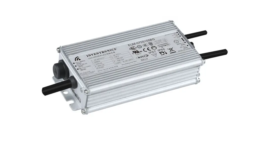
ESD-150SxxxDT
150W Programmable Outdoor Driver
Features
- Ultra-High Efficiency (Up to 94.5%)
- Full Power at Wide Output Current Range (Constant Power)
- Thermal Sensing and Protection for LED Module
- 0-10V/PWM/Timer Dimmable (3 Timer Modes)
- Dim-to-Off with Standby Power ≤ 1.5 W
- Output Lumen Compensation
- Input Surge Protection: 6kV line-line, 10kV line-earth
- All-Around Protection: OVP, SCP, OTP
- Suitable for UL Dry / Damp / Wet Location
- TYPE HL, for use in Class I, Division 2 hazardous
(Classified) location
Description
The ESD-150SxxxDT series is a 150W, constant-current, programmable LED driver that operates from 249-528 Vac input with excellent power factor. Created for high bay, tunnel and roadway lights, it provides a dim-off mode with low standby power. The high efficiency of these drivers and compact metal case enables them to run cooler, significantly improving reliability and extending product life. To ensure trouble-free operation, protection is provided against input surge, output over-voltage, short circuit, and over temperature.
Models
| Adjustable Output Current Range | Full-Power Current Range (1) | Default Output Current | Input Voltage Range (2) | Output Voltage Range | Max. Output Power | Typical Efficiency (3) | Power Factor | Model Number | |
| 277Vac | 480Vac | ||||||||
| 70-1050mA | 700-1050mA | 700 mA | 249-528 Vac 352-600 Vdc | 75-214Vdc | 150 W | 94.5% | 0.96 | 0.95 | ESD-150S105D1 |
| 140-2100mA | 1400-2100mA | 1400 mA | 249-528 Vac 352-600 Vdc | 38-107Vdc | 150 W | 94.0% | 0.96 | 0.95 | ESD-150S210DT |
| 245-3500mA | 2450-3500mA | 2800 mA | 249-528 Vac 352-600 Vdc | 22 — 61Vdc | 150 W | 93.0% | 0.96 | 0.95 | ESD-150S350D1 |
| 385-5600mA | 3850-5600mA | 4200 mA | 249-528 Vac 352-600 Vdc | 14 — 39Vdc | 150 W | 93.0% | 0.96 | 0.95 | ESD-150S560D1 |
Notes: (1) Output current range with constant power at 150W
(2) Certified input voltage range: 277-480Vac or 352-600Vdc
(3) Measured at full load and 480Vac input (see below “General Specifications” for details).
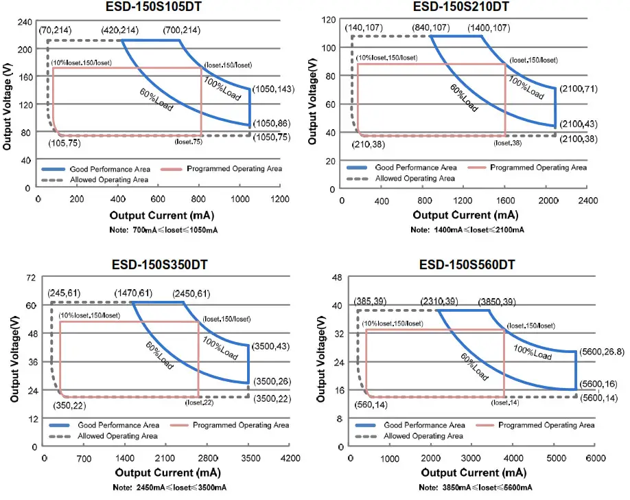
I-V Operating Area
Specifications are subject to changes without notice.
Input Specifications
| Parameter | Min. | Typ. | Max. | Notes |
| Input Voltage | 249 Vac | – | 528 Vac | 352-600 Vdc |
| Input Frequency | 47 Hz | – | 63 Hz | |
| Leakage Current | – | – | 1.0 MIU | At 480Vac/60Hz input, grounding effectively |
| Input AC Current | – | – | 0.70 A | Measured at full load and 277 Vac input. |
| – | – | 0.40 A | Measured at full load and 480 Vac input. | |
| Inrush Current(12t) | – | – | 7.6 A2s | At 480Vac input, 25°C Cold Start, Duration=680 us, 10%Ipk-10%Ipk. See Inrush Current Waveform for the details. |
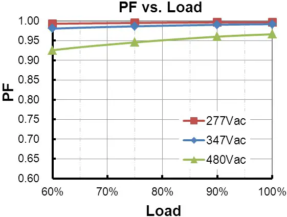
| PF | 0.90 | – | – | At 277-480Vac, 50-60Hz, 60%-100% Load (90-150W) |
| THD | – | – | 20% |
Output Specifications
| Parameter | Min. | Typ. | Max. | Notes |
| Output Current Tolerance | -5%loset | 5%loset | At full load condition | |
| Output Current Setting(loset) Rang ESD-150S105DT ESD-150S210DT ESD-150S350DT ESD-150S560DT | 70 mA 140 mA 245 mA 385 mA | – – – – | 1050 mA 2100 mA 3500 mA 5600 mA | |
| Output Current Setting Range with Constant Power ESD-150S105DT ESD-150S210DT ESD-150S350DT ESD-150S560DT | 700 mA 1400 mA 2450 mA 3850 mA | – – – – | 1050 mA 2100 mA 3500 mA 5600 mA | |
| Total Output Current Ripple (pk-pk) | – | 5%lomax | 10%lomax | At full load condition, 20 MHz BW |
| Output Current Ripple at < 200 Hz (pk-pk) | – | 2%lomax | – | At full load condition. Only this component of ripple is associated with visible flicker. |
| Startup Overshoot Current | – | – | 10%lomax | At full load condition |
| No Load Output Voltage ESD-150S105DT ESD-150S210DT ESD-150S350DT ESD-150S560DT | – – – – | 223 V 116 V 64 V 43 V | ||
| Line Regulation | ±–0.5% | Measured at full load | ||
| Load Regulation | +1.5% | |||
| Turn-on Delay Time | 0.8 s | 1.5 s | Measured at 277Vac and 480Vac input, 60%-100% Load | |
| Temperature Coefficient of loset | 0.03%/°C | Case temperature = 0°C -Tc max | ||
| 12V Auxiliary Output Voltage (Vaux) | 10.8 V | 12 V | 13.2 V | |
| 12V Auxiliary Output Source Current (laux) | 0 mA | – | 200 mA | Return terminal is –Dim-– |
Note: All specifications are typical at 25°C unless otherwise stated.
General Specifications
| Parameter | Min. | Typ. | Max. | Notes |
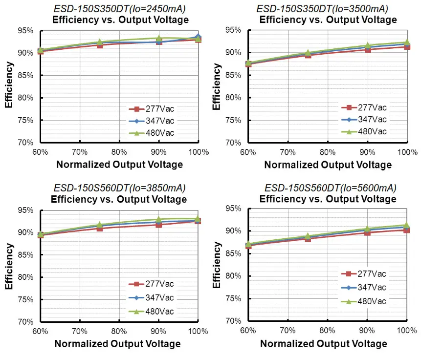
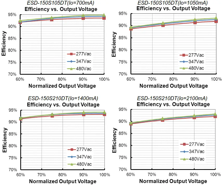
| Efficiency at 277 Vac input: ESD-150S105DT lo= 700mA 1o=1050mA ESD-150S210DT lo=1400mA lo=2100mA ESD-150S350DT lo=2450mA lo=3500mA ESD-150S560DT lo=3850mA 1o=5600mA | 91.5% 89.5%91.0% 90.0% 91.0% 90.5% | 93.5% 91.5%93.0% 92.0% 93.0% 92.5% | – — – – – | Measured at full load and steady-state temperature in 25°C ambient; (Efficiency will be about 2.0% lower if measured immediately after startup.) |
| Parameter | Min. | Typ. | Max. | Notes |
| Efficiency at 347 Vac input: ESD-150S105DT lo= 700mA lo=1050mA ESD-150S210DT lo=1400mA lo=2100mA ESD-150S350DT lo=2450mA lo=3500mA ESD-150S560DT lo=3850mA 1o=5600mA | 92.0% 90.5%91.5% 90.5% 91.5% 90.5% | 94.0% 92.5%93.5% 92.5% 93.5% 92.5% | – – – – | Measured at full load and steady-state temperature in 25°C ambient; (Efficiency will be about 2.0% lower if measured immediately after startup.) |
| Efficiency at 480 Vac input: ESD-150S105DT 1o= 700mA 1o=1050mA ESD-150S210DT lo=1400mA lo=2100mA ESD-150S350DT lo=2450mA lo=3500mA ESD-150S560DT lo=3850mA 1o=5600mA | 92.5% 91.0%92.0% 91.0% 91.0% 91.0% | 94.5% 93.0%94.0% 93.0% 93.0% 93.0% | – — – – – | Measured at full load and steady-state temperature in 25°C ambient; (Efficiency will be about 2.0% lower if measured immediately after startup.) |
| Standby power | – | – | 1.5 W | Measured at 480Vac/50Hz; Dimming off |
| MTBF | – | 203,000 Hours | – | Measured at 480Vac input, 80%Load and 25°C ambient temperature (MIL-HDBK217F) |
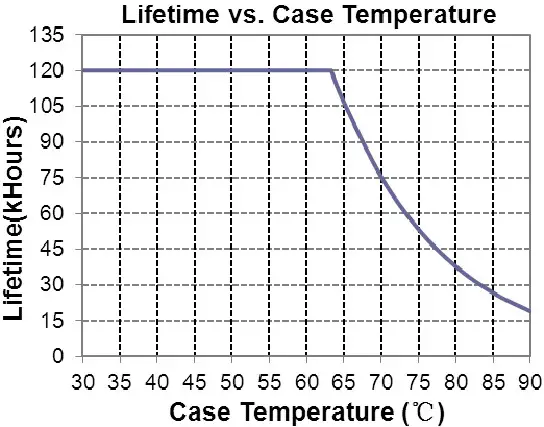
| Lifetime | 75, 000 Hours | Measured at 480Vac input, 80%Load and 70°C case temperature with laux=100mA; See lifetime vs. Tc curve for the details | ||
| Operating Case Temperature for Safety Tc_s | -40°C | – | +88°C | |
| Operating Case Temperature for Warranty Tc w | -40°C | +75°C | ||
| Storage Temperature | -40°C | – | +85°C | Humidity: 5%RH to 100%RH |
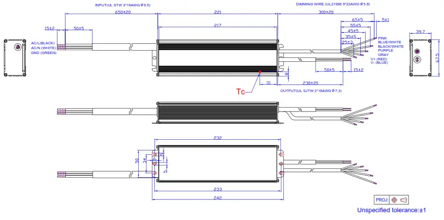
| Dimensions Inches (L x W x H) Millimeters (L x W x H) | 8.70 x 2.66 x 1.56 221 x 67.5 x 39.7 | With mounting ear 9.53 x 2.66 x 1.56 242 x 67.5 x 39.7 | ||
| Net Weight | – | 1300 g | – | |
Note: All specifications are typical at 25ºC unless otherwise stated.
Dimming Specifications
| Parameter | Min. | Typ. | Max. | Notes | |
| Absolute Maximum Voltage on the Vdim (+) Pin | -20 V | – | 20 V | ||
| Source Current on Vdim (+)Pin | 200 uA | 300 uA | 450 uA | Vdim(+) = 0 V | |
| Dimming Output Range | ESD-150S105DT ESD-150S210DT ESD-150S350DT ESD-150S560DT | 10%loset | – | loset | 700mA C loset C 1050mA 1400mA C loset C 2100mA 2450mA C loset r::: 3500mA 3850mA ,c; loset z7r: 5600mA |
| ESD-150S105DT ESD-150S210DT ESD-150S350DT ESD-150S560DT | 70mA 140mA 245mA 385mA | – | loset | 70mA ( loset < 700mA 140mA ( loset < 1400mA 245mA ( loset < 2450mA 385mA c: loset < 3850mA | |
| Recommended Dimming Input Range | 0 V | – | 10 V | Default 0-10V dimming mode. | |
| Dim off Voltage | 0.35 V | 0.5 V | 0.65 V | ||
| Dim on Voltage | 0.55 V | 0.7 V | 0.85 V | ||
| Hysteresis | – | 0.2 V | – | ||
| PWM_in High Level | 3 V | – | 10 V | Dimming mode set to PWM in PC interface. | |
| PWM_in Low Level | -0.3 V | 0.6 V | |||
| PWM_in Frequency Range | 200 Hz | 3 KHz | |||
| PWM_in Duty Cycle | 1% | 99% | |||
| PWM Dimming off (Positive Logic) | 2% | 5% | 8% | ||
| PWM Dimming on (Positive Logic) | 4% | 7% | 10% | ||
| PWM Dimming off ( Negative Logic) | 92% | 95% | 98% | ||
| PWM Dimming on ( Negative Logic) | 90% | 93% | 96% | ||
| Hysteresis | – | 2% | – | ||
Note: All specifications are typical at 25 ºC unless stated otherwise.
Safety & EMC Compliance
| Safety Category | Standard |
| UL/CUL | UL8750,CAN/CSA-C22.2 No. 250.13 |
| EMI Standards | Notes |
| FCC Part15(1) | ANSI C63.4 Class B |
| This device complies with Part 15 of the FCC Rules. Operation is subject to the following two conditions: [1] this device may not cause harmful interference, and [2] this device must accept any interference received, including interference that may cause undesired operation. |
Note: (1) This LED driver meets the EMI specifications above, but the EMI performance of a luminaire that contains it depends also on the other devices connected to the driver and on the fixture itself.
| EMS Standards | Notes |
| EN 61000-4-2 | Electrostatic Discharge (ESD): 8 kV air discharge, 4 kV contact discharge |
| EN 61000-4-3 | Radio-Frequency Electromagnetic Field Susceptibility Test-RS |
| EN 61000-4-4 | Electrical Fast Transient / Burst-EFT |
| EN 61000-4-5 | Surge Immunity Test: AC Power Line: line to line 4 kV, line to earth 6 kV |
| EN 61000-4-6 | Conducted Radio Frequency Disturbances Test-CS |
| EN 61000-4-8 | Power Frequency Magnetic Field Test |
| EN 61000-4-11 | Voltage Dips |
| EN 61547 | Electromagnetic Immunity Requirements Applies To Lighting Equipment |
Lifetime vs. Case Temperature
 Inrush Current Waveform
 Inrush Current Waveform
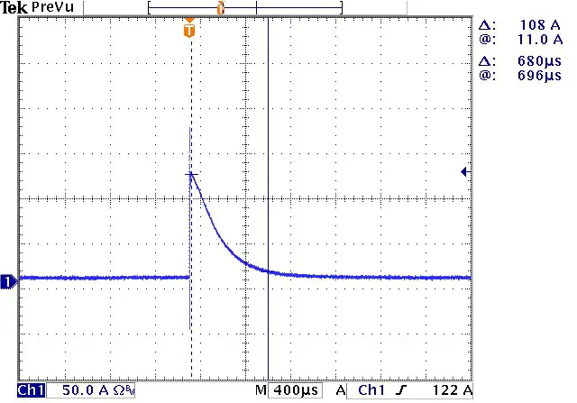
Efficiency vs. Load
 |  |
Power Factor
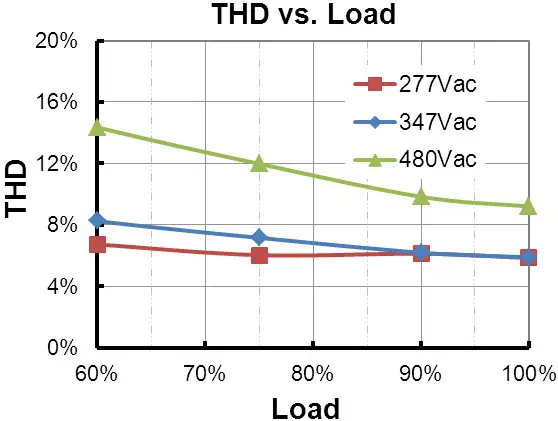
 Total Harmonic Distortion
 Total Harmonic Distortion
 Protection Functions
 Protection Functions
| Parameter | Notes | ||||
| Over Temperature Protection | Decreases output current, returning to normal after over temperature is removed. | ||||
| Short Circuit Protection | Auto Recovery. No damage will occur when any output is short-circuited. The output shall return to normal when the fault condition is removed. | ||||
| Over Voltage Protection | Limits output voltage at no load and in case the normal voltage limit fails. | ||||
| External Thermal Protection NTC | R1 | – | 7.81 kOhm | – | When R NTC falls below R1, External Thermal Protection is triggered, reducing output current until R2 is reached. |
| R2 | – | 4.16 kOhm | – | When R NTC is less than R2, the output current is reduced to the programmed “Protection Current Floor.” | |
| Protection Current Floor | 10%loset | 60%loset | 100%loset | 10%loset>lomin (default setting is 60%) | |
| login | 60%loset | 100%loset | 10%losetslomin (default setting is 60%) | ||
Dimming
0-10V Dimming
The recommended implementation of the dimming control is provided below.
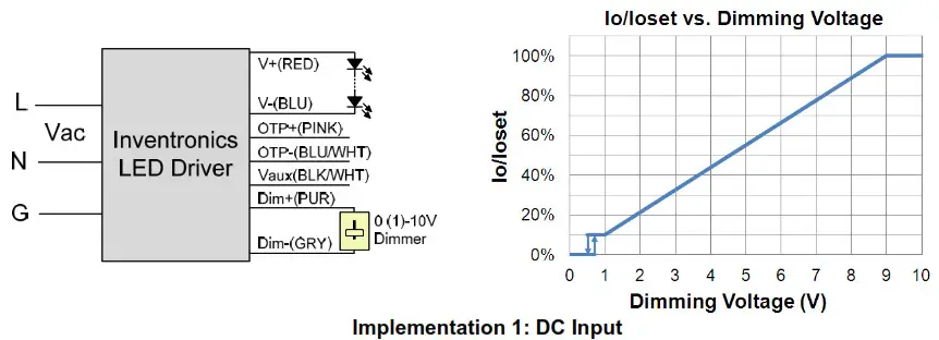
Notes:
- The dimmer can also be replaced by an active 0-10V voltage source signal or passive components like resistors and Zener.
- Do NOT connect Dim− to the output V− or V+, otherwise, the driver will not work properly.
- If 0-10V dimming is not used, Dim + should be open.
PWM Dimming
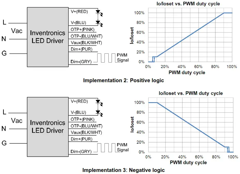
- Time Dimming
Time dimming control includes 3 kinds of modes, they are Self Adapting-Midnight, Self AdaptingPercentage, and Traditional Timer.=
• Self Adapting-Midnight: Automatically adjusts the dimming curve based on the on-time of the past two days (if the difference <15 minutes), assuming that the center point of the dimming curve is midnight local time.
• Self Adapting-Percentage: Automatically adjusts the on-time of each step by a constant percentage = (actual on-time for the past 2 days if difference <15 min) / (programmed on-time from the dimming curve).
• Traditional Timer: Follows the programmed timing curve after power on with no changes. - Output Lumen Compensation
Output Lumen Compensation (OLC) may be used to maintain constant light output over the life of the LEDs by driving them at a reduced current when new, then gradually increasing the drive current over time to counteract LED lumen degradation.
Programming Connection Diagram
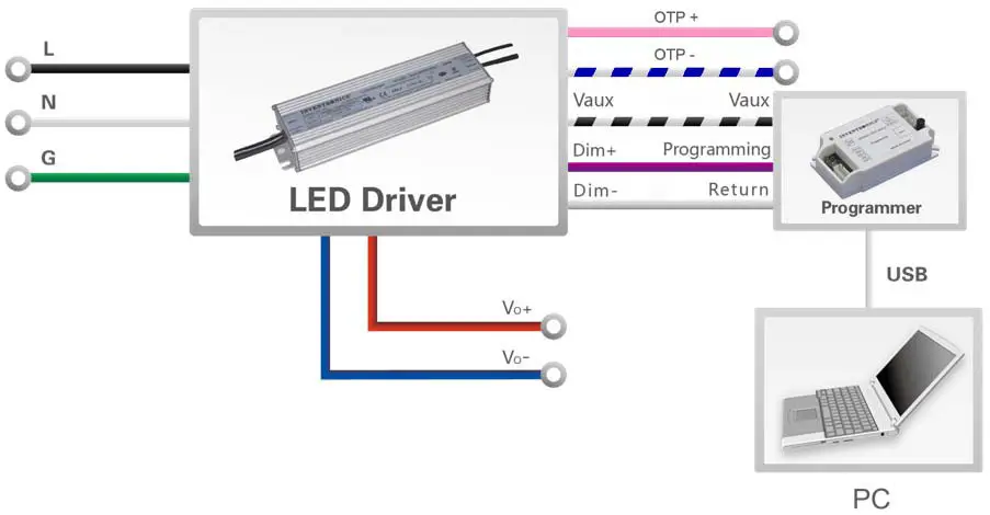
Note: The driver does not need to be powered on during the programming process.
- Please refer to the PRG-MUL2 Multi-Programmer datasheet for details.
Mechanical Outline
RoHS Compliance
Our products comply with the European Directive 2011/65/EC, calling for the elimination of lead and other hazardous substances from electronic products.
Revision History
| Change Date | Rev. | Description of Change | ||
| Item | From | To | ||
| 2015-09-23 | A | Datasheets Release | / | / |
| 2016-06-02 | B | Input AC Current | / | Updated |
| General Specifications | With mounting ear | Added | ||
| General Specifications | Net Weight | Added | ||
| Safety &EMC Compliance | Notes | Added | ||
| Programming Connection Diagram | / | Updated | ||
| Mechanical Outline | / | Updated | ||
| 2017-08-03 | C | Features | / | Updated |
| Input Specifications | PF/THD | Updated | ||
| Output Specifications | Turn-on Delay Time | Updated | ||
| Output Specifications | Temperature Coefficient of lost | Updated | ||
| Safety & EMC Compliance | / | Updated | ||
| Mechanical Outline | / | Updated | ||
Specifications are subject to changes without notice.
Tel: 86-571-56565800
Fax: 86-571-86601139
[email protected]


