RAM Audio MDi2 1K4-2K7-6K Professional Power Amplifiers
OPERATION MANUAL
SAFETY PRECAUTIONS
WARNING: The exclamation point inside an equilateral triangle indicates the existence of internal components whose substitution may affect safety. 
The lightning and arrowhead symbol warns about the presence of uninsulated dangerous voltage.
CAUTION
RISK OF ELECTRIC SHOCK DO NOT OPEN
To avoid fire or electrocution risk do not expose the unit to rain or moisture. To avoid electric shock, do not open the unit. No user-serviceable parts inside. In the case of disfunction, have the unit checked by qualified agents Class I devise.
Introduction
The MDI Series of amplifiers has been specifically developed for fixed installation and/or network applications. Thus they are equipped with specific connectors: XLR input and Speakon output, to offer clear, direct, and hassle-free connectivity. Furthermore, they offer up to 8 independent channels per unit to allow for as many zoning possibilities. Their unitary power output is dimensioned to suit specifically that type of installation.
The MDI Series incorporate unique absolute protections as the FCM™ or SSP™ systems.
Main Characteristics
- Eight, four, and two-channel models.
- Ultra-compact and lightweight 2-U high.
- Laser-cut aluminum front panel.
- FCM™ Faulty Channel Management system to avoid entire device shut-down.
- State-of-the-art layout for maximum performance and reliability.
- Detented sealed potentiometers for easy recall of volume settings.
- ICL, PROT, SIGNAL indicators per channel.
- Optional Add-on card to interface with third-party alarm systems with GPIO connections.
- ICL clip-limiters.
- Switchable (35Hz) sub-sonic highpass filter per channel.
- All channels are bridgeable by pairs.
- Temperature and signal dependant, intelligent cooling system for minimal noise.
- Highly oversized thermal dissipation design for maximum reliability.
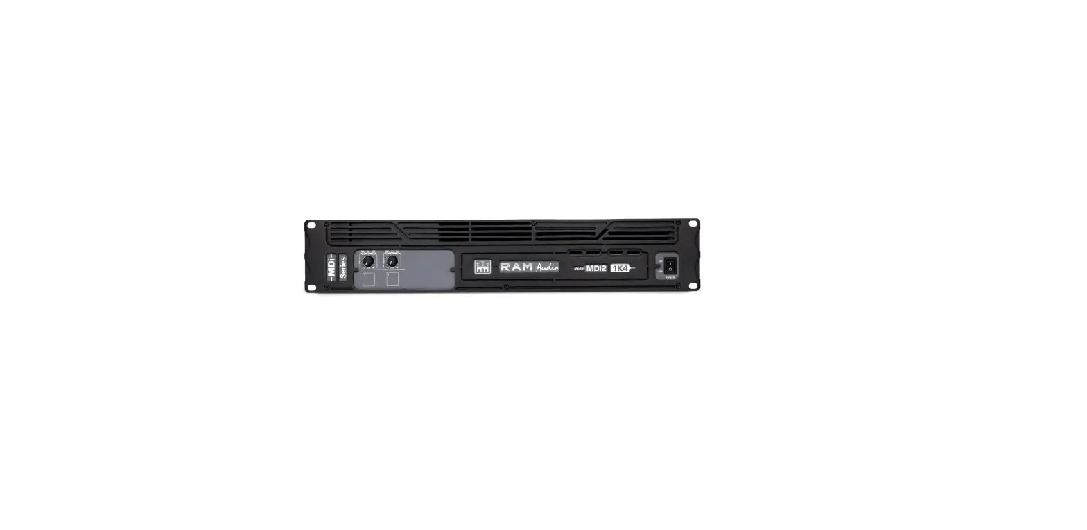
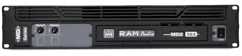
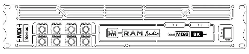
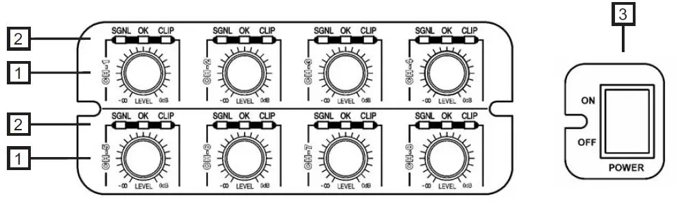
Front Panel
- Signal attenuation level control knobs: Permit independent control of each channel’s attenuation (21 steps).
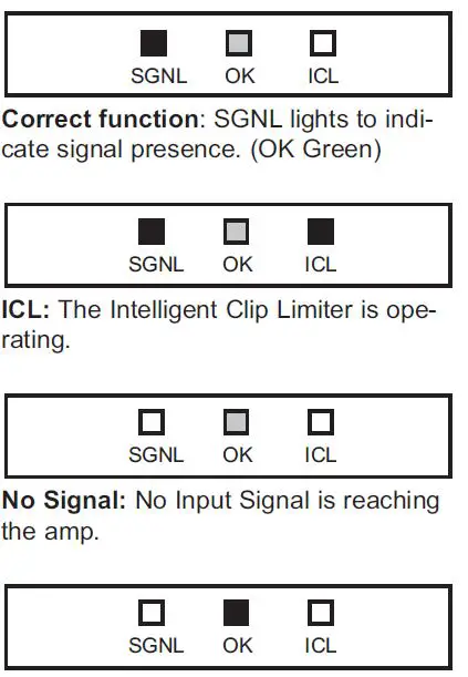
- SIGNAL: This LED indicates the presence of a signal at the inputs.
OK: This LED shows temperature protection is active (Red).
ICL: LED indicating Intelligent Clip Limiter in operation. - Main Power Switch: Position I: Connects the amplifier’s current feed. (OK green LED on). Position O disconnects the Power.
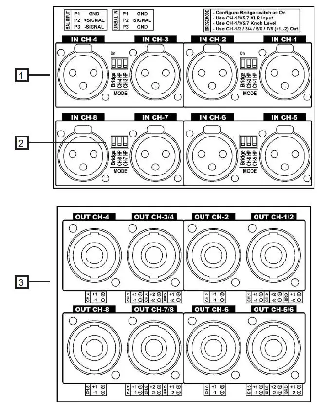
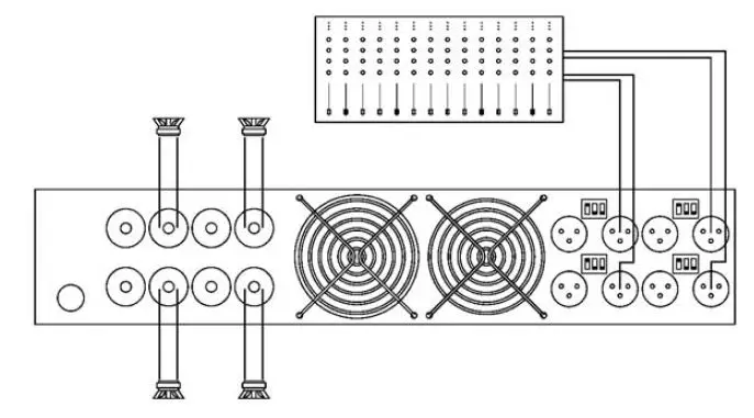
Rear Panel
- Signal Input: Female Neutrik® XLR Connectors for the amplifier’s signal input. Signal Link (MDi2/4): Male Neutrik® XLR Connectors for daisy-chaining input signal to other amplifiers.
- Configuration Switch: Subsonic filter (35Hz), and Bridge (see page 9).
- Speaker connectors: Neutrik® Speakon to connect the speakers.
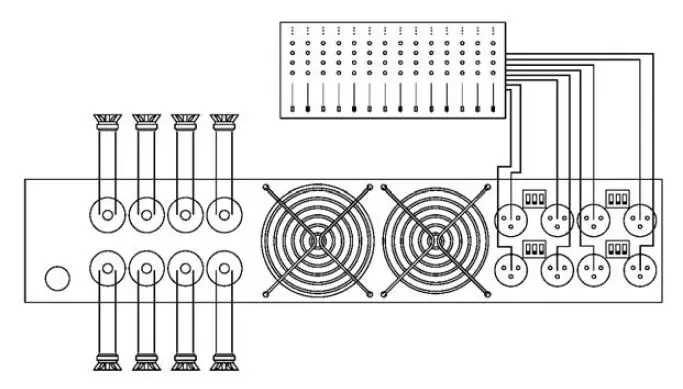
Connections
The Power switch must always be on the “Off” position before plugging the amp into a properly earthed mains socket (220-240V AC / 110V-120V AC). The input signal fed to the amplifier can be either balanced or unbalanced. The drawing below describes both ways to wire an XLR connector for the purpose.
Balanced Signal: Connect pin 1 to Ground, pin 2 to Signal + (hot), and pin 3 to Signal – (cold).
Unbalanced Signal: Connect Pin 1 to Ground, pin 2 to Signal and pin 3 to Ground.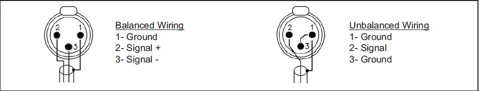
Important!: If a connection is done with an unbalanced line and pin – on the XLR is not connected to the ground, a 6 dB loss occurs in the line and only a quarter of the amplifier power is produced.
The amplifiers (MDi2/4) provide, for each channel, a female XLR Connector (Signal Input) paralleled to a male XLR to daisy chain several amplifiers with the same signal line (LINK).
Installation and Operation
The amplifier can operate on two different configurations: DUAL or BRIDGE. The connections for the two modes are different.
DUAL Channel Mode
- Switch “Off” the amp.
- Set the Configuration Minidips on the rear panel to NO Bridge (see page 9).
- Connect the signal lines to the XLR connectors on all channels.
- Connect the speakers’ lines to the corresponding Speakon on the amp respecting the polarity.
- Switch “On” the amp.
- Use the level control knob on the front panel to adjust each channel independently.
- Each signaling LED group will show its corresponding channel status.
BRIDGE Channel Mode
- Switch “Off” the amp.
- Set the Configuration Minidips on the rear panel to “BRIDGE” (see page 9).
- Connect a signal line to the XLR connectors Channel “1”, “3”, “5”, or “7”.
- Connect the speaker line to the Channel 1 Speakon (“3”, “5”, or “7”) wired to +1 and -2. In this way pin, +1 is positive.
- Switch “On” the amp.
- Use Channel “1” (“3”, “5” or “7”) control knob to adjust the amp’s output.
- The signaling LED groups will show the single-channel status.
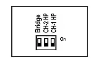
Configuration
The amplifier has an ensemble of mini-dips on the back panel, which allow for the following configurations: the high-pass subsonic filter, the Gain selection, and the bridge mode. All these configurations can be cross-set in any way, independently from the others. The basic configuration possibilities are as follows:
Standard Configuration: the amplifier works without a high pass subsonic filter, and no Bridge mode.
Sub-sonic Filter Enabled: the amplifier works with Channel 1 high pass subsonic filter (35Hz), and no Bridge mode.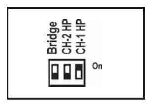
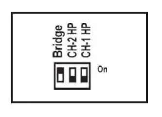
Bridge Mode: the amplifier works without a high pass subsonic filter, and Channel 1/Channel 2 Bridge mode.
Troubleshooting: In the event of an incorrect connection or misfunctioning, the amp will activate one or more of its LEDs to warn about the problem.
Protections: (OK Red) Several causes can trigger this LED, the most common are:
- Overheating: The amplifier has reached the maximum operational temperature. A most common cause is: the normal airflow is blocked, accumulated dirt, dust, or object leaning against the grill. Check and clean periodically.
- Short-circuit in the speakers’ line or in the speakers themselves.
- Low Impedance: check speakers’ connections or possible speaker dysfunction.
- DC in the output: the protections are activated to avoid damage to the speakers, the unit must be sent in for repair to a qualified technician.
- Delayed Start: As you switch on the amp the output to the speakers is dis-connected. After a few seconds, the amp will connect the speakers and proceed with normal functioning.
Data
| Technical Specifications | ||||||||
| MDi2-1K4 | MDi2-2K7 | MDi2-6K | MDi4-2K4 | MDi4-6K | MDi4-12K | MDi8-2K7 | MDi8-6K | |
| Max. Output Power | ||||||||
| @ 4ohm | 2×700 W | 2×1350 W | 2×3000 W | 4×610 W | 4×1500 W | 4×3000 W | 8×340 W | 8×750 W |
| @ 8ohm | 2×375 W | 2×900 W | 2×1500 W | 4×350 W | 4×800 W | 4×1500 W | 8×225 W | 8×400 W |
| Bridge @ 8ohm | 1×1400 W | – | – | 2×1220 W | – | – | 4×680 W | 4×1500 W |
| High Z | ||||||||
| 70Vrms/100Vpeak | – | 2×1350 W | – | – | 4×1500 W | – | 4×680 W | – |
| 100Vrms/140Vpeak | 1×1400 W | – | 2×3000 W | 2×1200 W | – | 4x3000W | 4×1500 W | |
| Frequency Response Power Bandwidth ±0.25dB | 20Hz-20kHz | |||||||
| Total Harmonic Distortion 20Hz-20kHz | <0.05% | |||||||
| Intermodulation Distortion SMPTE | <0.05% | |||||||
| Damping Factor (20Hz-500Hz @8ohm) | >400 | |||||||
| Crosstalk 20Hz-1kHz | >75 dB | |||||||
| Voltage Gain | 32dB | |||||||
| Sensitivity Rated Power @ 8W | 1.4 V | 2.1 V | 2.8 V | 1.3 V | 2 V | 2.8 V | 1.1 V | 1.4 V |
| Signal-to-Noise Ratio 20Hz-20kHz | 101 dBA | 103 dBA | 104 dBA | 105 dBA | 101 dBA | 103 dBA | 104 dBA | 104 dBA |
| Required AC Mains V AC (50Hz/60Hz) | 170-265 | 170-265 | 90-265 | 170-265 | 90-265 | 90-265 | 170-265 | 90-265 |
| Power On Idling (@230V) | 0.5 A | 0.5 A | 0.5 A | 0.5 A | 0.5 A | 0.5 A | 0.5 A | 0.5 A |
| @4ohm (1/8 rated power) | 1.8 A | 4 A | 4.5 A | 3.2 A | 4.5 A | 9 A | 4 A | 4.5 A |
| Dimensions | ||||||||
| W x H x D (mm) | 483×88.9×254 | 483×88.9×396 | ||||||
| W x H x D (inches) | 19×3.5×10 | 19×3.5×15.6 | ||||||
| Weight | ||||||||
| Net (Kg-lb) | 5-11 | 5-11 | 6-13.2 | 5-11 | 7.5-16.5 | 9.5-20.9 | 7.5-16.5 | 5-11 |
| Protections | ||||||||


