![]()
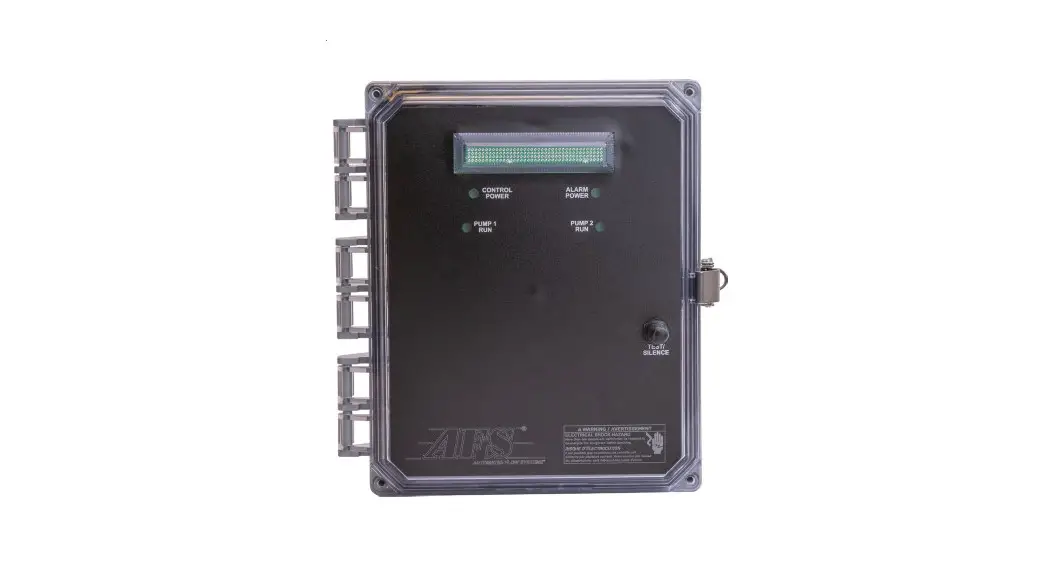
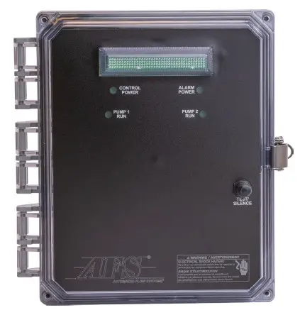 Duplex Dual Voltage Control Panel
Panel Model: AFSCPD120/240
Installation Instructions and Operation Manual
PRODUCT OVERVIEW
Applications
The AFS logic duplex control panel controls two pumps in residential and light commercial wastewater pumping applications, demand duplex pump control applications, and two pump reservoir pump up and alarm applications.
General
Offering a feature-rich duplex panel platform, the duplex logic panel offers an array of additional operating and data observation options. Our AFS engineers worked to provide a single duplex panel solution that fit nearly every typical application while providing heightened system operation data. Each panel features a lockable NEMA 4X enclosure, nearly silent power relays that are rated for 30 amps and 100,000 cycles, dual voltage pump operation, redundant OFF/low-level alarm, an Auto and Manual mode of operation, pump and controls circuit breakers, and an audible/visible high water level alarm with manual audible alarm silence and automatic reset. The AFS logic dual-mode duplex control digital backlit LCD provides pump control and historical system information, including float status, elapsed time pump run, cycle counter, alarm counts, and float error count features. The AFS digital dual-mode duplex panels can be used with either mechanical or mecury float switches and includes a simplified wiring diagram that is not removable from the interior of the panel.
Materials of Construction
| Enclosure | Polycarbonate | |
| Hinge | Polycarbonate | |
| Latch | Stainless steel | |
Specifications
| Height, in. (mm | 10.5 (292) |
| Width, in. (mm) | 10.25 (260.35) |
| Depth, in. (mm | 8.0 (203.2) |
| Panel ratings | 120, 208 & 240 VAC, 20 amps max, 1-phase, 60 Hz |
Features
| Programmable digital controller |
| Backlit LED display |
| Demand dose only mode |
| 120, 208 & 240 volt single phase motor control |
| Two wire pumps up to 20 amps |
| Nearly silent power relays rated for 30 amps and 100,000 cycles |
| Simplified wiring |
| Lockable NEMA 4X enclosure |
| Listed per UL-508 and cUL-508. |
Installation
- The AFS dual-mode duplex control panel is designed to operate with five, normally open signal floats when used in a pump down application like a sewage or septic pump system. These floats operate (from top to bottom), (1) high-level alarm, (2) lag pump ON, (3) lead pump ON, (4) Stop (OFF), (5) and redundant OFF/low-level alarm (optional with removal of the terminal link) functions.
- SJE Rhombus float type recommended for all 5 operations listed above: MilliAmpMaster Control Switch – Normally Open. The AFS float tree assembly model number AFSFT5-0 includes the five required floats, tree, and adjustable float clips to make float adjustment and installation quick and easy.
- All floats can be ordered with various cord lengths depending on application and depth of tank.
- The control panel can be mounted on an exterior wall or treated post near the pump tank area and should be mounted within visual site and 50’ of pump tank riser lid location as required by National Electric Code.
This control panel must be installed and serviced by a licensed electrician in accordance with National Electrical Code NFPA70, state and local electrical codes. Warranty void if panel is modified. |
PANEL COMPONENTS
Control Panel Components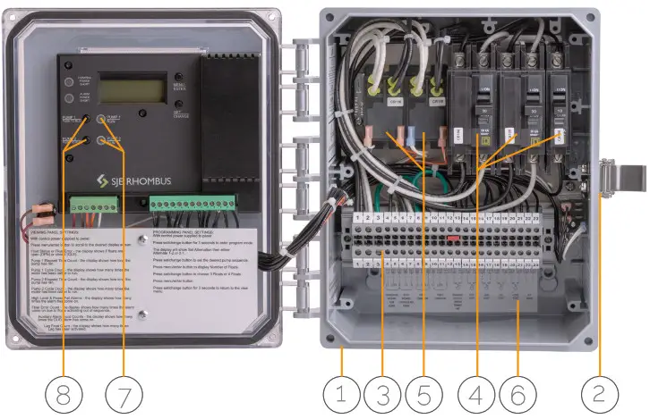
- 10.5” X 10.25” X 8” NEMA 4X enclosure rated for outdoor use
- Stainless steel lockable latch for added safety
- Large touch-safe terminal strip for easy wiring
- Three circuit breakers – two for pump power and a third for control and alarm power
- Pump run relays (30 amp), controls pump by switching electrical lines
- Simplified field wiring diagram inside box
- Pump run lights (pump run lights also on panel door exterior)
- Pump Push to Run switchs for easy control circuit troubleshooting
PANEL PROGRAMMING
Viewing Panel Settings
Press menu/enter button to view
- Float status or float error
- Elapsed time meter
- Cycle count
- High level & power fail alarm counts
- Float error counts
- Lag Float Count
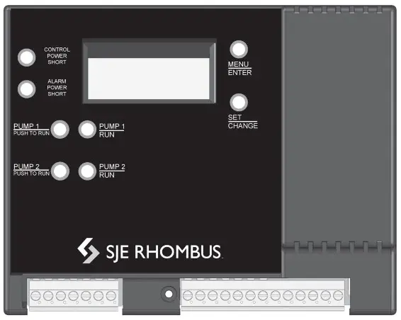
Programming Panel Settings
Press set/change button for 3 seconds to enter program mode
The display will show Set Alternation, then either Alternate, 1-2, or 2-1.
Press set/change button to set the desired pump sequence.
Press menu/enter button to display the number of floats.
Press set/change button to choose 3 Floats (eliminate the Lag float function) or 4 floats (add the Lag float function).
Press menu/enter button.
PANEL WIRING DIAGRAM
In Panel Wiring Connection Diagram
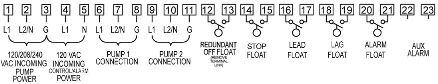
Complete Panel Wiring Schematic
On next page.
![]() Duplex Dual Voltage Control Panel
Duplex Dual Voltage Control Panel


