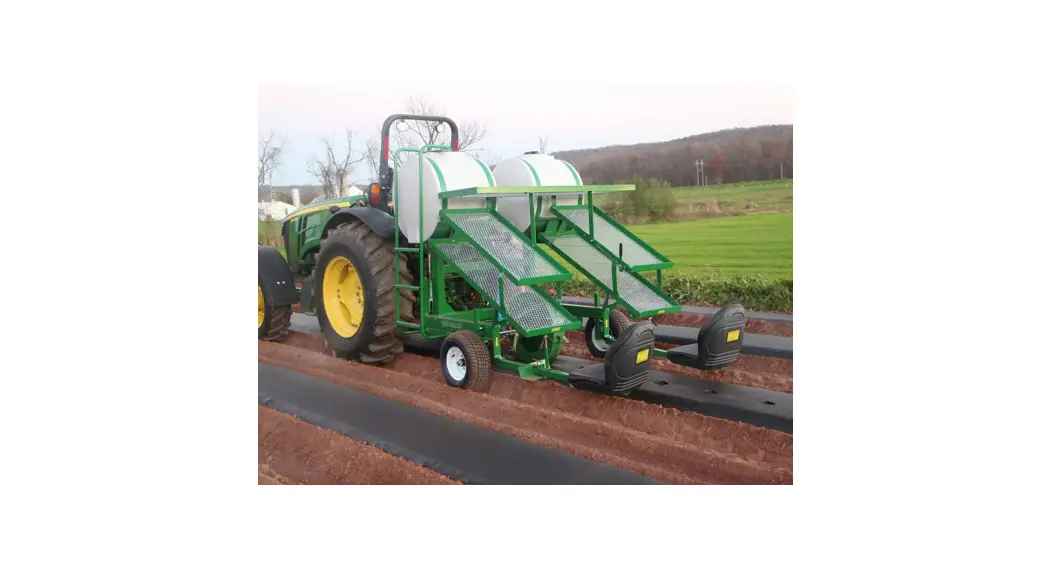
![]() IRRIGATION 1670 Water Wheel Transplanter
IRRIGATION 1670 Water Wheel Transplanter
Instruction Manual
Safety First
![]() No riders beyond the speed of 3 MPH. Be sure you read and understand all the precautions.
No riders beyond the speed of 3 MPH. Be sure you read and understand all the precautions.![]() Keep people away when lifting and lowering the machine.
Keep people away when lifting and lowering the machine.![]() Be careful when turning around; the machine is 8’ long.
Be careful when turning around; the machine is 8’ long.![]() Do not crawl under the machine when lifted.
Do not crawl under the machine when lifted.![]() Do not adjust the machine when it is moving.
Do not adjust the machine when it is moving.![]() Do not stand on the machine.
Do not stand on the machine.![]() Do not sit on the machine except on the designated seat.
Do not sit on the machine except on the designated seat.![]() Do not add chemicals to the water tank unless planters wear hand protection.
Do not add chemicals to the water tank unless planters wear hand protection.![]() Planter operators must keep their feet on foot rest when planting.
Planter operators must keep their feet on foot rest when planting.![]() Tractor operator is responsible for the extra worker(s) around the machine.
Tractor operator is responsible for the extra worker(s) around the machine.![]() Rain-Flo Irrigation is not responsible for accidents if any should occur.
Rain-Flo Irrigation is not responsible for accidents if any should occur.
PLANTING WHEEL ADJUSTMENTS
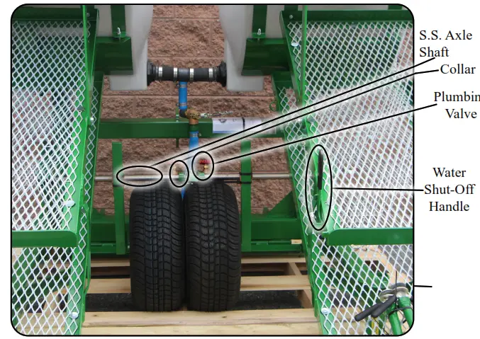
One to four planting wheels can be used at a time; the standard is one or two wheels. When using only one wheel, slide plumbing to one side of the wheel and keep one plumbing valve losed. Planting wheels are set in position with one bolt in the center of the wheel and can be moved sideways on the axle shaft. Planting wheels will flex up and down over uneven terrain.
Caution; Make sure planting wheels are not puncturing drip tape underneath the plastic.
Tire Axle Adjustment
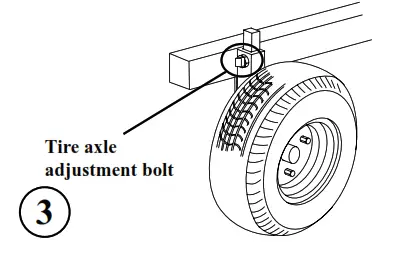
Tire axles need to be adjusted for high beds, and if more planting leg room is desired, shorten top link and lower tire axles.
SEAT ADJUSTMENTS
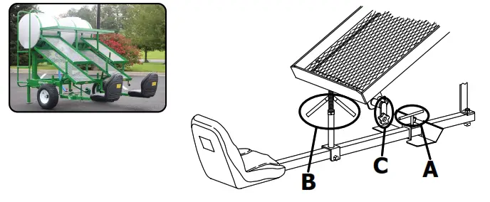
To adjust the footrest, loosen tee handle(A) and slide the footrest to the desired place. Turn handles(B) to adjust the seat height and handle(C) to adjust the seat’s “left-to-right” position for maximum comfort.
Installing 3rd and/or 4th seats Rain-Flo
The seat with heavy bar needs to be mounted toward the front and the seat with light bar to the back. Remove 1st and 2nd seats if they are already on the planter and install the 3rd and/or 4th seats by sliding seat adjuster(A) onto seat mounting bar(B) and fastening it with bolt and nut(C). Also, bolt end of seat mounting bar(B) onto frame with bolt and nut(D). Slide trays(E) and seat adjuster(F) onto 1st and 2nd seats and fasten it with bolt and nut(G) onto already installed 3rd and/or 4th seats as shown above.
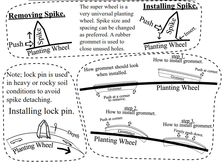
OPTIONAL SUPER WHEEL
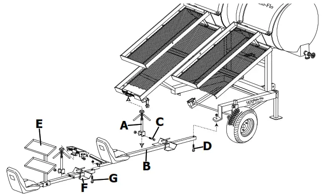
Optional traIler CombInatIon
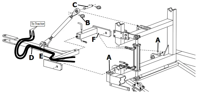
- Install drawbar tongue by sliding onto the lifting pins(A).
- Unsnap lynch pins(B), remove top link pin(C) and install as shown above.
- Slide hydraulic hoses through loops(D) and(E).
- Slide hitch bracket(F) onto lifting pin and over hitch tubing. Insert pin.
 |  |
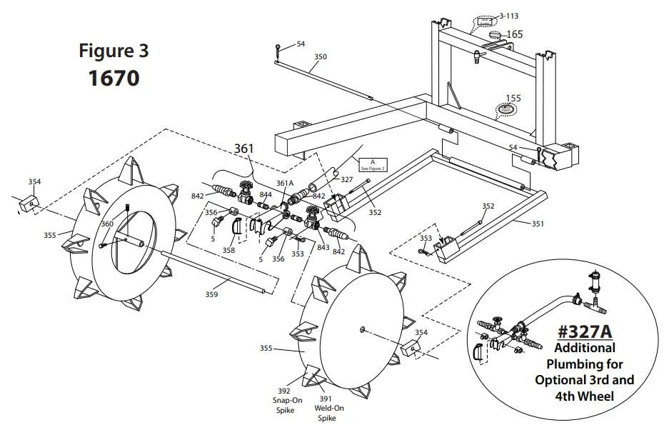 | 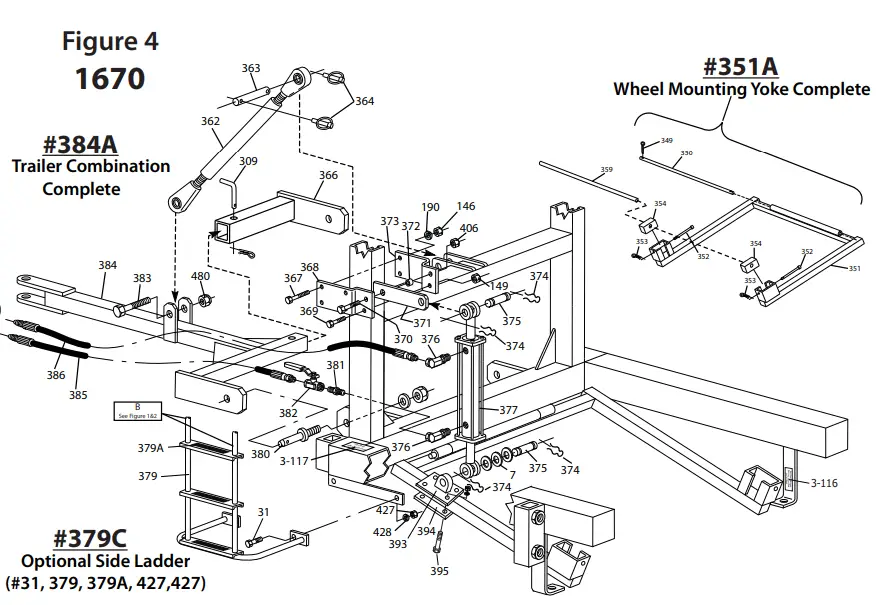 |
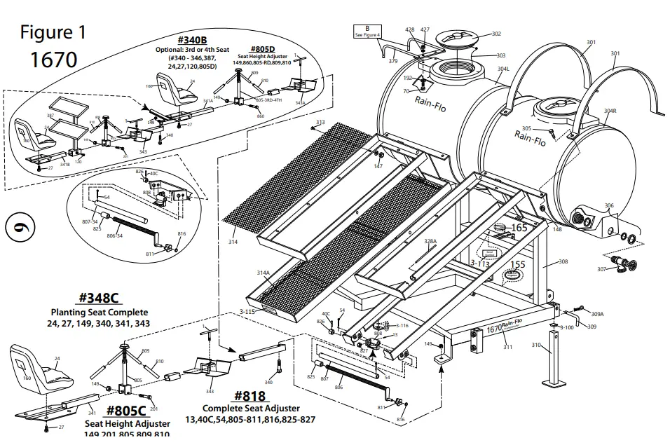
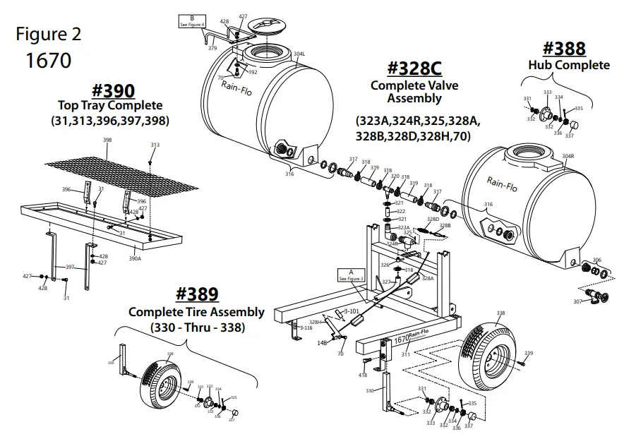
Model 1670 Transplanter
| Item…….. # …………………desCrIptIon 1………………(2) …………..Tee Handle 5………………(2) …………..⅜” x ¾” Sq. Head Set Screw 7……………………………….1” SAE Flat Washer 13…………….(2) …………..¼” NFT Straight Grease Zerk 24…………….(2) …………..Cushion Seat 27…………….(8) …………..5/16” x ½” Seat Bolt 31…………….(6) …………..⅜” x 1” Bolt 40C ………….(2) …………..¼” x 1” Roll Pin 54…………….(6) …………..⅛” Cotter Pin 70…………….(3) …………..⅜” x 1¼” Bolt 120……………………………½” x 1½” Bolt 146…………..(4) …………..½” Hex Nut 147………….(50) ………….¼” Nylon Lock Nut 148…………..(9) …………..⅜” Nylon Lock Nut 149…………..(5) …………..½” Nylon Lock Nut 155……………………………Rain-Flo Oval Logo 160…………..(2) …………..Important Notice Label on Seat 165…………………………… Use Top Hole For Higher Lift Label 190…………..(4) …………..½” Locking Washer 192…………..(2) …………..⅜” Flat Washer 201……………………………½” x 3¼” Bolt 301…………..(4) …………..Saddle Band 302…………..(2) …………..Tank Lid 303…………..(2) …………..Strap for Tank Lid 304L ………………………….80 Gal. Rain-Flo Tank w/ Tank Adapter 304R …………………………80 Gal. Rain-Flo tank w/ Valve 305……………………………⅜” x 2¼” Bolt 306……………………………¾” Tank Adapter 307……………………………¾” Drain Valve 308……………………………Frame 309…………..(2) …………..½” Quick Pin 309A ………..(2) …………..Safety Pin for ½” Quick Pin 310…………..(2) …………..Support Stand 311 …………..(2) …………..Model 1670 Label 312……………………………Seat Adjustment Label 313………….(50) ………….¼” x ¾” Zinc Elevator Bolt 314…………..(2) …………..Top Expanded Metal [20” x 43”] 314A ………..(2) …………..Bottom Expanded Metal [20” x 55”] 316…………..(2) …………..2” Tank Adapter 317…………..(2) …………..2” Male Adapter 318…………..(5) …………..2” Hose Clamp 319…………..(2) …………..2” Hose Extension (4” Long) 320……………………………2” x 2” x 1” Tee 321…………..(2) …………..1” Hose Clamp 322……………………………1” Hose Extension (5” Long) 323A. ………………………..1” Insert x Female Elbow 324R …………………………1” Planter Valve, [New Style For Cable Pull] 325……………………………1/16” x ¾” Cotter Pin 326……………………………Weld-on Male Adapter 327……………………………1” x 34” Hose Extension 327 A…………………………3rd and 4th Wheel Plumbing 328A …………………………On-off Valve Cable 328B …………………………Cable Adjustment Turnbuckle 328C …………………………Complete Valve Assembly 328D …………………………Valve Spring 328H …………………………Water Shut Off Handle 330…………..(2) …………..Axle Stem 331…………..(2) …………..Seal 332…………..(4) …………..Tapered Bearing 333…………..(2) …………..Metal Hub 334…………..(2) …………..¾” SAE Washer 336…………..(2) …………..¾” Fine Thread Lock Nut 337…………..(2) …………..Cap 338…………..(2) …………..20.5 x 8.0 – 10 Tire & Rim 339………….(10) ………….½” Lug Bolt 340…………..(4) …………..½” x 3½” Bolt 340A …………………………½” x 4” Bolt 340B …………………………Optional 3rd or 4th Seat Complete w/ 3 41…………..(2) …………..Seat Mounting Bar 341A …………………………Optional 3rd or 4th Seat Bracket Only 343…………..(2) …………..Foot Rest 343A …………………………Foot Rest for 3rd or 4th Seat 348C …………………………Seat Assembly Complete 350……………………………Yoke Hinge Pin 351……………………………Wheel Mounting Yoke 351A …………………………Wheel Mounting Yoke Complete 352…………..(2) …………..Bushing Locking Pin 353…………..(2) …………..Safety Pin 354…………..(2) …………..UHMW Block Bushing 355……………………………Planting Wheel (Specify Spacing & Spike 356…………..(2) …………..Plumbing Collar 358……………………………Snap Pin 359……………………………1” x 45¼” Stainless Steel Shaft 360……………………………½” x 1” Sq. Head Set Screw 361……………………………Two Valve Plumbing Assembly | 361A …………………………Two Valve Plumbing Tee Adapters Only 362……………………………Top Link (16” Body) 363……………………………Top Link Pin 364…………..(2) …………..Lynch Pin 366……………………………Tongue Bracket 367…………..(4) …………..½” x 4¾” Bolt 368……………………………Cylinder Mount; Left Side (From Back) 369……………………………½” x 2¾” Bolt 370……………………………¾” x 3” Bolt 371……………………………Cylinder Hinge Plate 372…………..(2) …………..Hinge Plate Spacer 373……………………………Cylinder Mount; Right Side (From Back) 374…………..(4) …………..Cylinder Snap Pin 375…………..(2) …………..Cylinder Attach Pin 376…………..(2) …………..Hyd. Flow Restrictor; ⅜” MB x ⅜” FP 377……………………………Hydraulic Cylinder; 2½” x 6” 379……………………………Ladder 379A ………..(3) …………..Ladder Step Traction Tape 379C …………………………Side Ladder Complete 380…………..(2) …………..Cat II Lift Pin 381……………………………⅜” Nipple 382……………………………⅜” Hydraulic Ball Valve 383……………………………1” x 5” Bolt 384……………………………Draw Bar Tongue 384A …………………………Trailer Kit Complete 385……………………………⅜” x 99” Hydraulic Hose 386……………………………⅜” x 106” Hydraulic Hose 387……………………………3rd and 4th Seat Top Tray 388…………..(2) …………..Hub Complete 389…………..(2) …………..Tire Assembly Complete 390……………………………Top Tray Complete (Includes Brackets) 390A …………………………Top Tray Bracket Only 391……………………………Weld-On Spikes 392……………………………Snap-On Spikes 393……………………………Cylinder Yoke Bracket 394…………..(4) …………..Cylinder Yoke Bracket Plate 396…………..(2) …………..Top Tray Front Bolt-On Plate 397…………..(2) …………..TopTray Bolt-On Plate 398……………………………Top Tray Expanded Metal (20” x 69”) 406……………………………¾” Lock Nut 418…………..(4) …………..⅝” x 1½” Set Screw 427………….(10) ………….⅜” Nut 428………….(10) ………….⅜” Lock Nut 480……………………………1” Lock Nut 3-100 ……….(2) …………..Rubber Stand Cap 3-101 ………………………..Water Shut-Off Handle Plastic Grip 3-113 …………………………Serial Number Plate 3-115 ………..(2) …………..For More Leg Room Label 3-116 ………..(2) …………..Bolt Seat Tubing on Bottom Label 3-117 …………………………Close Valve When Transporting Label 805…………..(2) …………..Seat Adjuster Bottom Tube Assembly 805-3rd-4th ………………..Seat Adjuster Bottom Tube Assembly for 805C …………………………Seat Adjuster Assembly Complete 805D …………………………3rd or 4th Seat Adjuster Assembly Complete 806…………..(2) …………..Threaded Rod w/ Hand Crank 806-34 ………………………3rd or 4th Seat Threaded Rod w/ Hand Crank 807…………..(2) …………..Seat Adjustment 1” Rod 807-34 ………………………3rd or 4th Seat Adjustment 1” Rod 808…………..(2) …………..Seat Adjustment Hanger 809…………..(2) …………..Seat Adjuster Upright Threaded Rod 810…………..(4) …………..Seat Adjuster Handle Rubber Grip 811 …………..(2) …………..Seat Adjuster Knob 816…………..(2) …………..Seat Adjuster Knob Cap 818……………………………Seat Adjuster Complete 826…………..(2) …………..Adjuster Threaded Rod Collar w/ Roll Pin 827…………..(2) …………..¾” x 6” ACME Thread Nut 842…………..(3) …………..¾” Male Adapter 843…………..(2) …………..¾” Brass Gate Valve 844…………..(2) …………..¾” Short Brass Nipple 860……………………………½” x 3¾” Bolt |
Features
- The capability of 8” to 36” Row Spacing and One to Four Planting Wheels. (Standard)
- Four Slanted Galvanized Expanded Metal Trays
- Specialty Designed Tanks so Tractor Operator Can See People Planting; Making it Easier to Communicate
- More Water Capacity, Two 80 Gallon Tanks (Total 160 Gallons)
- Quick Change Water Wheel Setup
- Easy Seat Adjustment for Comfort and Foot Rest Adjustment
- Large Tires with Highway Bearings
- Will Plant 60” Row Centers Minimum
- Side Valve for Washing Hands
- Quality Powder Coated Paint
Options
- Optional Super Wheel (Spike Changes too Many Sizes & Spacings)
- Optional Side Ladder
- Optional Top Tray
- Optional 3rd & 4th Seat with Trays
- Optional Trailer/3-Point Combination
Warranty
All Rain-Flo Water Wheel Transplanters has a two-year warranty against defects in material and workmanship. If any part is found defective, return the defective part with a Serial No. of the machine. If Rain-Flo finds it defective, it will be replaced or repaired at no charge.
Call Customer Service at (717) 445-3000.
Helpful Tips
For the best crop stand, planting operators should firmly press plants into the water-filled hole. If plenty of water is used, potted plants will be sealed and do not need to be covered ith soil. When using starter fertilizer, it needs to be agitated. Fertilizer is heavier than water and will settle to the bottom of the tank, resulting in possibly burning or killing the first couple hundred plants.
For faster planting, operators may put one tray of plants on their lap.
If soil does not paste to the planting wheel, this machine can also be used on bare soil.
TROUBLESHOOTING
- PROBLEM: A planter is used on bare soil, and soil tends to paste onto the planting wheel.
SOLUTION: *Soil is too wet or wheel needs to be cleaned or repainted. - PROBLEM: Not enough leg room.
SOLUTION: *Adjust footrest. See Page 4. *Adjust top link and axle. See Page 3. - PROBLEM: Tractor can’t lift planter.
SOLUTION: *Optional trailer hitch available. See Pages 5 & 9 *Keep less water in tanks.
![]() ~ 2021 Edition ~
~ 2021 Edition ~
Rain-Flo Irrigation
(717) 445-3000


