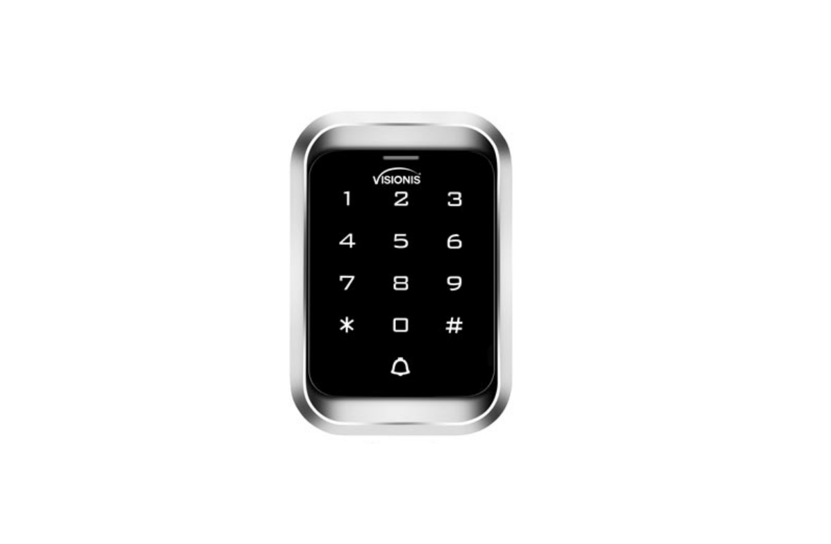
VISIONIS VIS-3000 Access Control for Single Door
Description
The device is a standalone as well as a Wiegand access control keypad and proximity card reader which supports EM and HID card types, il’s one of the most advanced standalone access control. Its build-in USA Atmel microprocessor, with strong anti-interference ability, high security and reliability, powerful function and convenient operation. It is widely used in high-end buildings, residential communities and other public places. This device can be used as standalone and also connected to a central Access Control Panel.
Features
- Ultra-low power consumption: Standby current is less than 30mA.
- Input& Output: Wiegand26.
- Reading Time: Less than 0.1 s after reading card.
- Backlight Keypad: Easy to operate at night.
- Doorbell interface: Support external wired doorbells.
- Entry Methods: Card, code, card+code.
- Pin only: Card are not necessary if you choose pin only method.
- Change Codes: Users can change codes by themselves.
- Anti-tamper alarm: The alarm is activated if device is torn off or illegally removed.
- Delete Users by card NO, Delete card NO via keypad to reduce security issues.
Specification
- Input Voltage: DC 12V
- Idle Current: 25mA
- Card reading distance: 2°3 cm
- Card Frequency: 125KHz for EM and HID
- Card transmission format: wiegand26
- Keypad transmission format:4bit,8bit and Virtual card number
- Operating Temperature: -45•c-ss• C (-49F -131 F)
- Operating Humidity: 0%-95%
Installation
Install base plate onto wall and attach device using bottom screw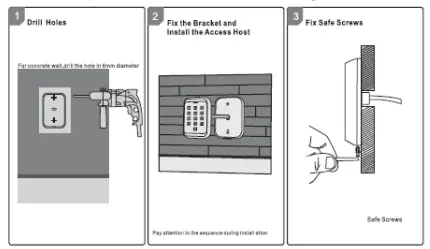
WRITING
| No. | Marks | Color | Description |
| 1 | BELL A | Pink | Doorbell button |
| 2 | BE L_B | Pink | Doorbell button |
| 3 | DO | Green | Wiegand output DO |
| 4 | D1 | White | Wiegand output D1 |
| 5 | +12V | Red | Positive pole of power supply |
| 6 | GND | Black | Negative pole of power supply |
| 7 | OPEN | Yellow | Exit button |
| 8 | O_I N | Brow n | Door contact |
| 9 | ALARM | Gray | Alarm Output |
| 10 | NO | Blue | Relay NO end |
| 11 | COM | Purple | Relay Com end |
| 12 | NC | Orange | Relay NC end |
Sound and Light Indication
| Operation | LED Color | Buzzer |
| Standby | Red flash | |
| Press key | Di | |
| Read card | Green | Di- |
| Door Open | Green | Di- |
| Operation Successful | Green | Di- |
| Operation Failed | Di Di Di | |
| PIN Inputting | Red | |
| Card&PIN Inputting | Red | |
| Multi-Card Reading | Red | |
| Under Menu | Red | |
| Under Setting | Orange | |
| Manager Card Enter | Orange | Di Di |
| Manager Card Exit | Red Flash | Di- |
| Alarm | Red Quick Flash | Alarm |
Quick Programming Guide
Administrator Setting
| Stand by | Master Code | Menu | Setting | Remarks | Functions |
| Red Flash | Red | Red | Orange | ||
|
* |
Master code# (Code length: 6–8 digits) | 00 | New master code# Repeat new master code # | Factory default: 999999 | Change the master code |
| 01 | Read Manager Add Card | Set Manager Add Card | |||
| 02 | Read Manager Delete Card | Set Manager Delete Card | |||
| 03 | Read Anti- duress card | Set Anti-duress card | |||
| 05 | Anti-duress PIN# | Set Anti-duress PIN | |||
| 07 | 0000# | Delete All Users | |||
| 51 | Master open Lock |
System Setting
| Stand by | Master Code | Menu | Setting | Remarks | Functions | |
| Red Flash | Red | Red | Orange | |||
| 30 | 0-15 # | Default 0 | To set facility code | |||
| 0# | Wiegand reader mode | |||||
| Master | 31 | 1 # | Unable to initialize | Standalone mode (factory default setting) | ||
| 5# | Anti•passback mode | |||||
| code# | ||||||
| 32 | 26 # | Defaul t 26 | To set Wiegand format | |||
| (Code | ||||||
| * | length: 6-8 digits) | |||||
| 33 | 0-2 # | Unable to initialize | To set keypad transmission format | |||
| 34 | 1- 3 # | Defaul t 1 | To set alarm time | |||
| 0# | Safe mode 0 | |||||
| 35 | 1 # | Default 0 | Safe mode 1 | |||
| 2# | Safe mode 2 |
User Setting
User Optional Setting
| Stand by | Master Code | Menu | Setting | Remarks | Functions | |
| Red Flash | Red | Red | Orange | |||
| 0 # | Buzzer will be in silence except | |||||
| 41 | enter the programming mode | |||||
| 1 # | Default 1 | Buzzer will sound when press | ||||
| the key | ||||||
| Master | 0# | Disable keypad backlight | ||||
| code# | ||||||
| 1 # | Enable keypad backlight | |||||
| * | (Code length: 6-8 | 42 | ||||
| 2# | Default 2 | Automatic mode | ||||
| digits) | ||||||
| 43 | 0 # | LED Light Disable when | ||||
| stand•bv status | ||||||
| 1 # | Default 1 | LED is constantly flash when | ||||
| stand-bv status |
Instruction
- Master code must be 6-8 digi, ts, Anti-duress PIN must be 8 digits, user PIN is 4-6 digits,
- The user ID number is 1•4 digits, which can be any number among 1-2000, invalid o can be omitted; card number must be 8 or 10 digits, if the card number is less than 8 or 10 digits, input O before the card number,
- Door open time is 0-99 seconds,0=50mS
- When register one card user into the device, the device wil automatically generate a PIN 1234, but this PIN 1234 can’t open the door, you need to change PIN 1234 to other numbers to open the doo
- When an invalid master pin is pressed, the device will go back to the standby status after 5 seconds, when a valid master pin is entered, it will go back to standby status after 30 seconds.
- In operating the keypad, pressing # means to confirm the input digits,In operation of a cycle adding or deleting cards, pressing # means to end the cycle operation and back the up operation; pressing • means to exit the operation.
- When add a series cards, this uni t will make the ID number and card number as initial value; after adding one user, then it will increase the ID number and card number automatically until the specified number of card is added. The card number must be consecutive card quantity is between 1-2000,
- Working mode and keypad transmission format have been set before shipping, customer can change according to requirement, but cannot be restored to factory settings by initialization,
- When users is registered successfully, LED will turn green.
Administrator setting
Adminis trator setting on keypad Press • Master code # factory detault:999999.
Change the master code
Press 00 new code repeat new master code #
Note: Master Code length: 6-8 digits.
Set Manager Card
Set manager add WordPress 01 read manager add card
Set manager delete card
Press 02 read manager delete card
Note: When add the new manager card, the new one will automatically cover the old card, only one manager cara 10r one dEvE
Set Anti-duress card
Press 03 read anti-duress card
Note: when add the new antidiuresis card, the new one will automatically cover the old card, only one address card for one device.
Set Anti-duress PIN
Press 05 8-digit duress PIN #
Note:
The anti-duress pin is 8 digits. When set the new anti-duress PIN, the new one will automatically cover the old ant-duress PIN, only one ant-duress PIN for one device.
Delete all users
Press 07 0000 #
Note: Al users wil be deleted. This is a dangerous option, so use with care.
Set administer open lock
Set administer open Lock Press 51 #
Users setting
Read card to add user
Press 11 read card # read card #
Use ID Number and read card to add user
Press 11 ID number # read card. ID number # read card#
Use card number
Press 11 card number #.. card number # ..#
Delete user
Read card to delete user
Press 12 read card.. #
Use ID number to delete user
Press 12 ID number # ID number # . #
Use card number to delete user
Press 12 card number # card number #.. #
Delete all users
Press 07 0000 #
Note: All users will be deleted.
Set opening door mode
Entry is by card only
Press 13 0#
Entry is by card and PIN together
Press 13 1 #
Entry is by card or PIN (factory default)
Press 13 2 #
set door relay time
Press 14 0-99 #
Note: 0-99 is to set the door delay time 0-99 seconds, factory default is 5 seconds,
Set Relay mode
Relay setting -pulse mode
Press 15 0#
Every time a valid card/tag read or PIN input, the relay il operates, for the pre-set relay
pulse time. (Factory default setting)
Relay setting-Toggle mode
Press 15 1 #
Every time a valid card/tag read or PlN input, the relay changes state, which will not tum
Dack read card lag or input FiN again.
Set opening door by multi cards
Press 16 card quantity #
Note: It is only for card entry mode (Factory defaut setting: 1, card quantity 1-10).
Add a series consecutive cards users
Press 17 ID number # card number # card quantity #
Note The card number must be consecutive card quantity is between 1-2000, card number is 10 digits or 8 digits.
System setting
To set facility code
Press 30 0-15 #
Note: Code should be -15, factory defaut setting: 0.
Wiegand Reader Mode (Wiegand 26)
Press 31 0#
Standalone Mode (Factory default setting)
Press 31 1 #
Anti-passback Mode
Press 31 5#
To set Wiegand format
Press 32 26 #
Note: factory default setting: WG26,
Setting keypad transmission format
Press 33 0-2 # (Unable to initialize)
Note: Keypad transmission format is 0 12, factory default is 0,
Setting alarm time
Press 34 1-3 # (Unable to initialize)
Note: 1. factory default is 1 minute.
Setting safe mode
Normal mode (factory default)
Press 35 0 #
Dead mode
Press 35 1 #
If read invalid card or input wrong PIN 10 times in 10 minutes, system will be dead for 10 mins,
Alarm mode
Press 35 2#
if read invalid card or input wrong PIN 10 times in 10 minutes, external alarm and buitin buzzer will work, User optional setting
Setting buzzer silence in non-setting state
Press 41 0#
setting buzzer to normal work (Factory default setting)
Press 411#
Setting keypad backlight
Disable keypad backlight
Press 42 0#
Enable keypad backlight
Press 42 1 #
Automatic mode (factory default setting)
Press 42 2 #
The keyboard light is off during standby, the right is on when press key,
Setting LED light (standby status)
Disable LED light
Press 43 0 #
Flash LED light (factory default setting).
Press 43 1 #
Manager card operation
Add user
Read Manager Add Card, read user cards continuously, read Manager Add card again.
Delete user
Read Manager Delete Card, read user cards continuously, read Manager Delete card again.
User Operation
Entry by card mode,
Set muti cards to open door when card quantity is 1.
Read user card, lock will be unlocked.
Entry by card mode,
Set muti cards to open door when card quantity is 2-10.
Read these cards one by one, present each card in 5 seconds, lock will be unlocked.
Entry by card and PIN
Present card, then press PIN (4 to 6 digits), #, lock wi be unlocked.
Entry by card or PIN mode
Present card, lock will be unlocked. Or Press PIN (4 to 6 digits), #, lock will be unlocked.
Relay mode
Relay setting -pulse mode
Every time a valid card/tag read or PIN input, the relay will operate, for the pre-set relay pulse time.
Relay setting-Toggle mode
Every time a valid card/tag read or PIN input, the relay changes state, which will not tum back until read card/tag or input PIN again,
Modify user PIN (no need enter programming mode)
road user card, press old 4 to 6 digits PIN, #, new 4 to 6 digits PIN #,repeat new 4 to 6 ss ID number # old 4 to 6 digits PIN,# ,new 4 to 6 digits PIN # ,repeat new 4 to 6 digits PIN #
Notice: User who do not have user card must get |D number and origin PIN from Admin.
Alarm Function
Anti-tamper alarm
IF the device is disassembled illegally, the buZzer and the external alam will operate.
Door contact alarm
When connecting with door contact, if the door is opened legally, the buzzer and the extemal alarm wordie.
The Anti-duress alarm
When reading anti-duress card or input &-digit anti duress PIN, then press #, the coresponding bck il open, at the same time, the extemal alam il operate, but the device buZzer il not operate.
Remove alarm
Read valid user card, manager card or input master code, then alarm will be removed. If no any operation, alam will be removed automatically.
Connection Diagram
NONC Locks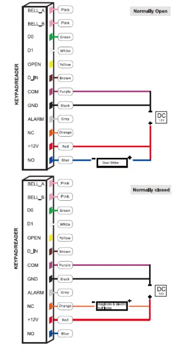
Connection with Accessories: Doorbell and Exit button 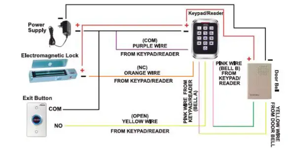
Connection with Accessories: Doorbell, Exit button, and Wireless Receiver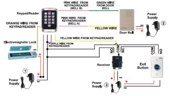
Connection with Accessories: Doorbell, Exit button, and PIR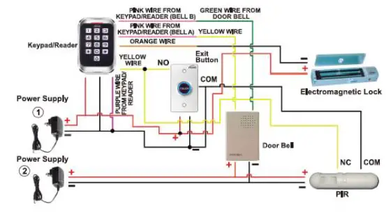
Connection with Access Control Panel 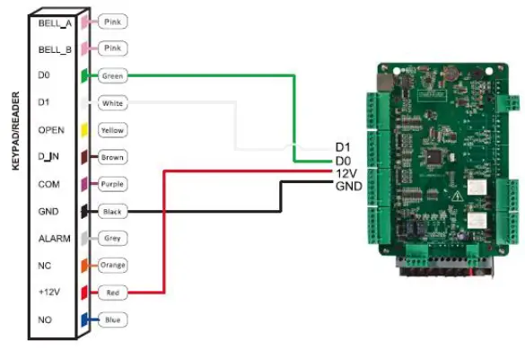
Reset to Factory Default
- Power off.
- Press and hold # key. then power on.
- Release # key until hearing short beeps twice. When hearing long beep once, the device is in normal working state and reset to factory default setting, but the user data wl not be deleted.
Packing list
| Name | Model/size | Quantity | Remarks |
| Keypad | 1 | ||
| User manual | 1 | ||
| Self-tapping screws | (!)4mm• 28 mm | 2 | Used in fixing |
| Rubber plug | (!)6mm• 30 mm | 2 | Used in fixing |
| Star screwdriver | (!)20mm•60mm | 1 | Special for Keypad |
- Please do not to repair the device privately, if you have problems, please return to the supplier.
- Before installing on the wall, please check carefully concealed wiring or wire tube, in case of broken concealed wiring etc, when drilling, please use safe glasses.
- If the product updated, manual may be different, Without Prior Notice.
FCC Statement
Changes or modifications not expressly approved by the party responsible for compliance could void the user’s authority to operate the equipment.
This equipment has been tested and found to comply with the limits for a Class B digital device, pursuant to Part 15 of the FCC Rules. These limits are designed to provide reasonable protection against harmful interference in a residential installation. This equipment generates uses and can radiate radio frequency energy and, if not installed and used in accordance with the instructions, may cause harmful interference to radio communications. However, there is no guarantee that interference will not occur in a particular installation. If this equipment does cause harmful interference to radio or television reception, which can be determined by turning the equipment off and on, the user is encouraged to try to correct the interference by one or more of the following measures:
- Reorient or relocate the receiving antenna.
- Increase the separation between the equipment and receiver.
- Connect the equipment into an outlet on a circuit different from that to which the receiver is connected.
- Consult the dealer or an experienced radio/TV technician for help
This device complies with part 15 of the FCC rules. Operation is subject to the following two conditions (1)this device may not cause harmful interference, and (2) this device must accept any interference received, including interference that may cause undesired operation. This equipment complies with FCC radiation exposure limits set forth for an uncontrolled environment.


