![]() 16/24 Port Fast Ethernet PoE
16/24 Port Fast Ethernet PoE
Switch, 1 Combo (RJ45+SFP) and 1 RJ45 Gigabit Uplinks
Quick Installation Guide
DN-95355 – DN-95356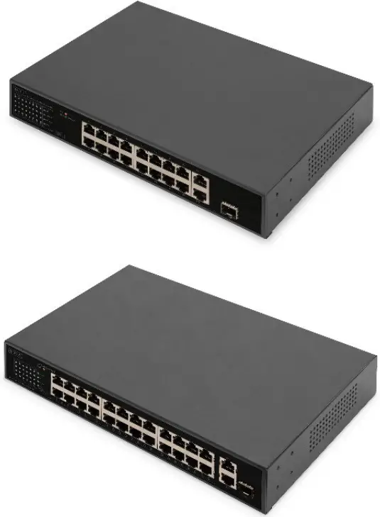
Introduction
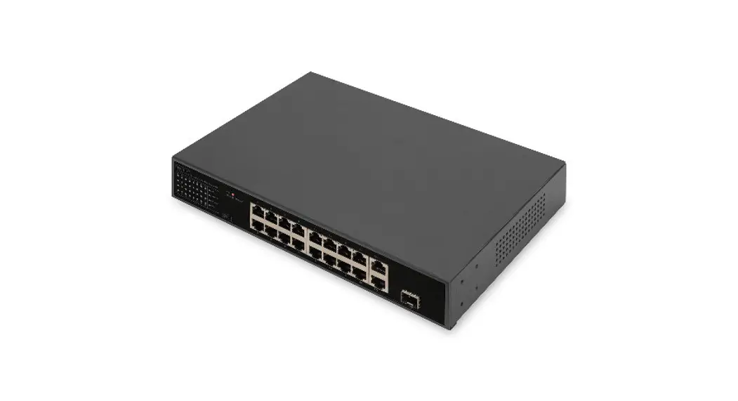
DN-95355 PoE Switch is 16-port 10/100Mbps PoE + 1G Combo + 1GE PoE Switch.
DN-95356 PoE Switch is 24-port 10/100Mbps PoE + 1G Combo + 1GE PoE Switch.
The PoE ports can automatically detect and supply power to IEEE802.3af/at compliant Powered Devices (PD).
The electrical power and data transmission on the same cable can expand your network to the places where no power lines or outlets, where you can install devices such as APs, IP cameras, or IP phones etc.
The PoE Switch provides a simple, cost- effective, and non-blocking wire-speed performance with 11-inch metal shape for rack deployment in office or department network application.
Features
- 16/24x 10/100Mbps PoE RJ45 Ports
- 1x 10/100/1000Mbps Combo Ports
- 1x 10/100/1000Mbps RJ45 Port
- Support VLAN and CCTV function
- Complies with IEEE802.3af/at Power over Ethernet
- Supports PoE Power up to 32W for each PoE port
- Auto detect power device
- Remote power and Data feeding up to 100m
- Flow Control for Full Duplex operation and back pressure for Half Duplex Operation
- 16K MAC address, automatic address learning and address aging
- Support Energy-Efficient Ethernet (EEE) function EEE802.3az
- Support PD Alive function (the switch port is disconnected will automatically connected)
Package Contents
- 1x PoE Switch
- 1x User Guide
- 1x Power Cord
- Accessories (hanging ears x2, Rubber Feet x4, screw x8)
Specifications
| Model | DN-95355 | DN-95356 |
| PoE Port | Port 1-16 | Port 1-24 |
| Standards and Protocols | IEEE802.3, IEEE802.3u, IEEE802.3ab, IEEE802.3z, IEEE802.3x, IEEE802.3af, IEEE802.3at | |
| Network Media | • 10BASE-T: UTP category 3,4,5 cable (≤ 100m), • 100BASE-TX: UTP category 5, 5e cable (≤ 1OOrn), • 1000BASE-T: UTP category 5e, 6 cable (≤100m), • 1000BASE-X: SMF, MMF SFP module | |
| Transfer Method | Store-and-Forward | |
| Frame Forward Rate | • 10Base-T: 14881pps/Port • 100Base-TX: 148810pps/Port • 1000Base-T/X: 1488095pps/Port | |
| Switching Capacity | 7.2G | 8.8G |
| Fan | lx Fan | |
| Power Input | AC: 100-240V, 50/60Hz | |
| Packet Forwarding Rate | 5.4Mpps | 6.5Mpps |
| Packet Buffer | 4Mbit | 4Mbit |
| PoE Power on RJ45 | Mode A 1/2(+),3/6(-) | |
| PoE Power Output | Voltage: 55V DC Power: 32W(Max) | |
| PoE Power budget | 185W | |
| Dimensions (W x D x H) | 280x180x44mm | |
| Temperature | • Operating Temperature: 0°C ∼ 40°C (32 °F ∼104°F) • Storage Temperature: -40°C ∼ 70°C (-40 °F ∼158°F ) | |
| Humidity | • Operating Humidity: 10% ∼ 90% non-condensing • Storage Humidity: 5% ∼ 90% non-condensing | |
Hardware Description
5.1 Front Panel
The Front Panel Consists of 16/24-Port 10/100M Auto-Negotiation Ethernet RJ45 Ports, 1-Port Gigabit Combo Port and 1x 10/100/1000 RJ45 port. The LED indicators also on located on the panel.
DN-95355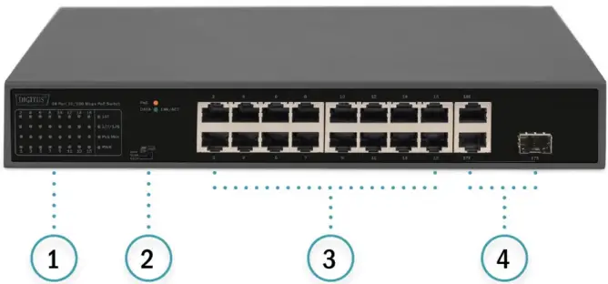
| 1. Status indicators | 2. Switch |
| 3. 16x 10/100MbpsPoE RJ45 Ports | 4. 1x 10/100/1000Mbps Combo Ports 1x 10/100/1000Mbps RJ45 Ports |
DN-95356: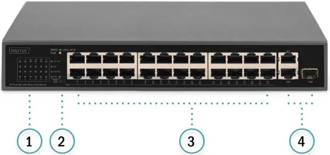
| 1. Status indicators | 2. Switch |
| 3. 24x 10/100Mbps PoE RJ45 Ports | 4. 1x 10/100/1000Mbps Combo Ports 1x 10/100/1000Mbps RJ45 Ports |
LED indicator:
| LED | Color | Function |
| PWR | Green | Off: No Power supply Light: Indicates the switch has power |
| LNK/ACT | Green | Off: No device is connected to the corresponding port. Light: Indicates the link through that port is successfully. Blink: Indicates that the Switch is actively sending or receiving data over that port. |
| PoE | Orange | Off: No PoE powered device (PD) connected Light: There is a PoE PD connected to be port, which supply power successfully. Blink: Indicates port abnormal power supply |
| Max | Green | Off: PoE power is less than 80% of total power. Light: PoE power above 80%. |
DIP Switch
The DIP switch located on the left panel.
Default: the factory default mode, can normal communication between port 1~18/1~26.
VLAN: 1-16/24 port can be isolated each other but 1-16/24 port can connect to 17~18/25~26 port after open VLAN to stop broadcast storm to increase forwarding rate of frame.
CCTV: Up to 250m PoE distance allows you to expand you network via Ethernet cable but where you want to fix device such as IP Cameras.
Note:
After change the mode, there is no need to restart manually to make the corresponding configuration take effect.
5.2 Rear Panel
The rear panel of the PoE Switch indicates an AC inlet power socket, Grounding Column. 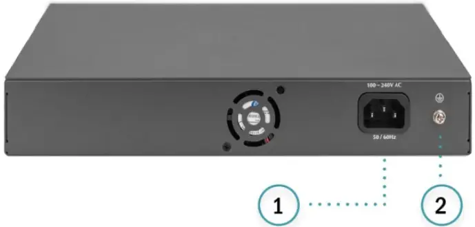
- AC power socket
- Grounding
Installation the Switch
This part describes how to install your Ethernet Switch and make connections to it. Please follow the following instructions in avoid of incorrect installation causing device damage and security threat.
- Before cleaning the switch, unplug the power plug of the switch first. Do not clean the switch with wet cloth or liquid;
- Do not place the switch near water or any damp area. Prevent water or moisture from entering the switch chassis;
- Do not place the switch on an unstable case or desk. The switch might be damaged severely in case of a fall;
- Ensure proper ventilation of the equipment room and keep the ventilation vents of the switch free of obstruction;
- Make sure that the operating voltage is the same one labeled on the switch;
- Do not open the chassis while the switch is operating or when electrical hazards are present to avoid electrical shocks
6.1 Desktop Installation
Install the Switch on a desktop, please attach these cushioning rubber feet provided on the bottom at each corner of the Switch in case of the external vibration. Allow adequate space for ventilation between the device and the objects around it. The installation diagram is as follows: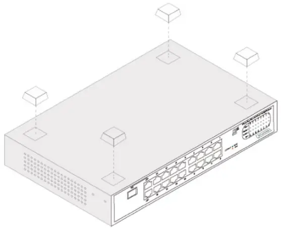 6.2 Rack-mountable Installation
The switch is rack-mountable and can be installed on an EIA-11-inch equipment rack. To do this, first, please install the mounting brackets on the switch’s side panels (one on each side), secure them with the included screws, and then use the screws provided with the equipment rack to mount the switch on the 11-inch rack.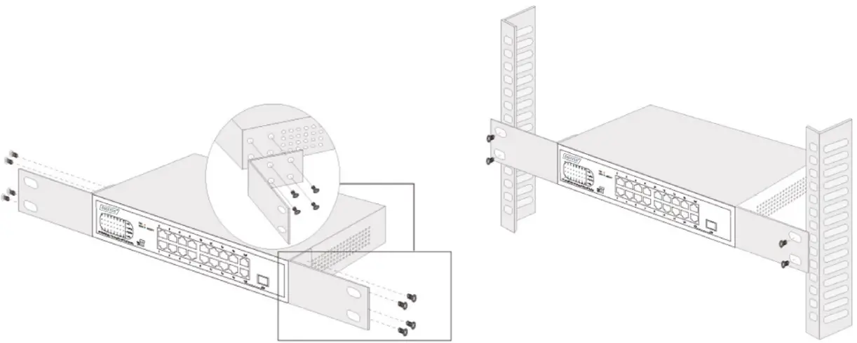 6.3 Turn on the switch
Plug in the negative connector of the provided power cord into the power socket of the device, and the positive connector into a power outlet.
After the device is powered on, it begins the Power-On Self-Test. The PWR LED indicator will light on all the time.
CE Mark Warning: This is a Class A product. In home environment, this product may cause radio interference. In this case, the user may be required to take appropriate measures.
Hereby Assmann Electronic GmbH, declares that the Declaration of Conformity is part of the shipping content. If the Declaration of Conformity is missing, you can request it by post under the below mentioned manufacturer address.
www.assmann.com
Assmann Electronic GmbH
Auf dem Schüffel 3
58513 Lüdenscheid
Germany![]()


 Plus 2g Combo Poe Switch Installation Guide")


