![]() Quick Start Guide
Quick Start Guide
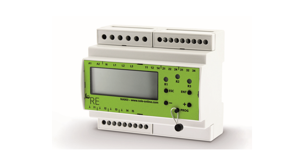
NA003-M64
doc no.: 090750A
Part No.: 2700000
www.tele-online.com
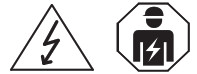 Danger! Never carry out work on live parts!
The danger of fatal injury!
The product must not be used in case of obvious damage! To be installed by an authorized person only!
- The full operation manual is available at: http://www.tele-online.com/resources/data-sheets/en_na003.pdf
- This Quick Start Guide does not replace the manual and the owner should read in conjunction with the whole Manual.
- The safety instructions are to be observed
Intended use:
The TELE NA003-M64 is a multinational grid and system protection unit, that protects energy generation plants ( like combined heat and power plants, wind generators, waterpower plants, photovoltaic plants).
In case of power failures or net anomalies, power generating plants have to be disconnected immediately from the main supply to avoid unintentional feeding to the grid. On the one hand continuing grid feeding could endanger maintenance staff, on the other hand, connected devices could be exposed to inadmissible voltages and/or frequencies.
In case the grid operator requires thresholds and settings that are not conforming with the local standards, it is possible to set thresholds outside the normative defined range!
Outside this range, the device is not in accordance with the standards anymore and the corresponding certificate loses validity! This state is indicated as „ncnf“ [none conformity] on the display.
Settings outside the conformity range are therefore in the responsibility of the operator respectively the acceptance authority!
Safety advice:
The device was developed, produced, and tested in accordance to the latest industry standards. Nevertheless improper handling or use can endanger humans and machines.
Please use the device only in accordance with the installation and operating instructions. Check for secure assembly and good condition. Moreover, the rules and regulations on accident prevention applicable to the place of use must be strictly followed.
- Eliminate all faults immediately which may endanger safety!
- Do not make any unauthorized changes and only use replacement parts and optional accessories purchased from or recommended by TELE!
- In case of obvious damage, the device must be checked and replaced if necessary!
- Country-specific regulations have to be considered in any case!
- If required by national standards, the NA003 has to be protected against unauthorized changes by password and/or sealing!
Mounting on DIN rail according to EN 60715:
Snap the rear mounting clip of the device into place in such a way that a safe and tight fit is ensured.
Available configurations/Local standards:
CEI 0-21:2019, VDE 0126-1-1:2013, VDE 0124-100:2013, VDE 4105:2018 <50kW, VDE 4105:2018 >50kW, VDE 4105:2018 Umr, G59/3/3:2015 LV, G99/1/3:2018 LV, G59/3/3:2015 MV, G99/1/3:2018 HV, G83/2:2012, G98/1/2:2018, C10-11:2012 LV, C10-11:2019 LV-IP, C10-11:2019 LV-ASS, C10-11:2012 MV, C10-11:2019 HV-IP, C10-11:2019 HV-ASS, TR3 Rev23:2013, VDE 4110:2018 TR3-25, OVE E 8001/8101:2014, OVE TOR R25 NS SYNC, OVE TOR R25 NS ASYNC, OVE TOR R25 MS SYNC, OVE TOR R25 MS ASYNC, EN50438:2013, EN50438:2013 DK, NRS 097-2-1:2017, OPEN SETUP
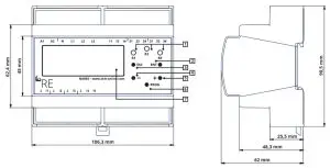
Dimensions:
Controls elements:
| Legend | Marking | Type | Function |
| 1 | R1, R2, R3 | LED (yellow) | Status indication output relays |
| 2 | ENT | Pushbutton | ENTER, Input confirmation, menu level forward |
| 3 | ESC | Pushbutton | ESCAPE, Input rejection, menu level back, test/reset |
| 4 | – | Pushbutton | Change parameters, menu navigation |
| 5 | + | Pushbutton | Change parameters, menu navigation |
| 6 | PROG | Pushbutton (sealable) | PROGRAM, enter program mode |
| 7 | 0 | LCD-Display 4×20 characters | Display |
Terminals:
| At, A2 | Supply | DC: 24V AC: 110 – 230V @ 1: 48-63 Hz Al: L (+) A2: N (-) |
| Ll, L2, L3, N | Measuring input | UN: 3x400V AC |
| 11, 12 14 , | Relay channel A (CO contact) Status indication via yellow LED R1 | Isolated changeover contact 11:Common 12:Normally closed contact 14: Normally open contact |
| 21, 22, 24 | Relay channel B (CO contact) Status indication via yellow LED R2 | Isolated changeover contact 21:Common 22:Normally closed contact 24: Normally open contact |
| 31, 32, 34 | Relay channel D (CO contact) Status indication via yellow LED R3 | Isolated changeover contact 31:Common 32:Normally closed contact 34: Normally open contact |
| it,_L | Digital input 1 (Feedback contact contactor A) | Contact input (24V/5mA) Input active: II connected to ┴ |
| 12, _L | Digital input 2 (Feedback contact contactor 8) | Contact input (24V/5mA) Input active: 12 connected to┴ Does not apply to national standards without functional safety! |
| 13, s | Digital input 3 (Remote disconnection) | Contact input (24V/5mA) Input active: 13 connected to ┴ |
| 14,15, _L | Digital inputs 4 and 5 (Parameter switchover) Applies to CEI 0-21 | Contact input (24V/5mA) Input active: 14 or 15 connected to ┴ |
Technical data:
| Supply circuit | ||
| Supply voltage: | DC: 24V | AC: 110 – 230V |
| Supply voltage tolerance: | DC: ± 10% | AC: ± 30% |
| Nominal consumption: | max. 1,25W / 4VA @ 230V AC | |
| Rated frequency: | 50 / 60Hz | |
| Tolerance of rated frequency: | 48 – 63Hz | |
| Rated surge voltage: | 6 kV | |
| Internal protection: | 250V / 500mA slow blow (soldered) | |
In order to ensure the proper function during power failures, an external UPS has to be used.
| Measuring circuit | |
| Measuring input: | 3 x 400V AC |
| Input impedance: | 1MΩ |
| Measurand: | line to line voltage, line to neutral voltage, 10 minutes average voltage, frequency, rate of change of frequency (RoCoF), phase shift (shift) |
| Measuring ranges | |
| Line to line voltage: | 0 – 560VAC |
| Line to neutral voltage: | 0 – 325VAC |
| Frequency: | 40 – 65Hz |
| RoCoF: | 100mHz/s … 2.000mHz/s |
| Pshift: | 1 – 15° |
| Overload capacity: | Permanent 1,4 x UNom Pulse 1,6 x UNom (1 second) |
| Overvoltage category: | III |
| Rated surge voltage: | 4 kV |
| Digital inputs | |
| Type of contact: | potential-free |
| Min. switching voltage/ switching current: | 24V DC / 5mA |
| Output circuit | |
| Number of contacts: | 3 changeover contacts |
| Contact | AgNi |
| Rated current: | 5A / 250V AC |
| Electrical endurance: | 100 x 103 switching cycles (AC-1) |
| Mechanical endurance: | 15 x 106 switching cycles |
| Continous current value: | 5A |
| Short time value (1s): | 5A |
| Withstanding voltage across open contacts: | Relay contacts: 1000Vrms Terminals: 450Vrms |
| Overvoltage category: | III |
| Rated surge voltage: | 4 kV |
| Protection: | 5A fast blow |
| Accuracy Voltage monitoring: | |
| Base accuracy: | < 0,5% @ +25°C |
| Temperature influence: | < 0,01% / °C |
| Resolution: | 10mV |
| Frequency monitoring: | |
| Base accuracy: | < 0,01Hz @ +25°C |
| Temperature influence: | < 0,0002Hz / °C |
| Resolution: | 1mHz |
| Isolation data | |
| Rated insulation voltage: | 400V |
| Supply circuit / Measuring circuit: | protective insulation |
| Supply circuit / Output circuit: | protective insulation |
| Supply circuit / Digital inputs: | protective insulation |
| Output circuit / Measuring circuit: | basic insulation |
| Output circuit / Digital inputs: | basic insulation |
| Environmental conditions | |
| Ambient temperature operation: | -25 … +55°C |
| Ambient temperature storage: | -40 … +70°C |
| Visibility temperature display: | -15 … +55°C |
| Relative humidity: | 5 … 95% (non-condensing) |
| Degree of contamination: | 2 |
| Weight: | 300g |
| Electrical connection | |
| Wire size: | max. 2,5mm2 |
| Stripping length: | max. 8mm |
| Electrical strength: | max. 450V/16A (digital inputs; relay outputs) max. 750V/16A (measuring inputs) |
| Torque: | max. 0,5Nm |
| Screw: | M3, slot screwdriver 0,6 x 3,5mm |
| Protection class | Terminals: IP20 Housing: IP20 |
Connection diagram 1:
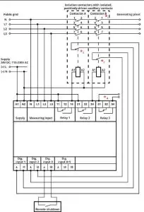 | |
| Applies to: » VDE 0126-1-1:2013 » VDE 0124-100:2013 » *1,*4 VDE 4105:2018 <50kW VDE 4105:2018 >50kW, » *4 VDE 4105:2018 Umr, » *1 VDE 4110:2018 TR3-25 » *1 G99/1/3:2018 LV, G99/1/3:2018 HV, G98/1/2:2018, G59/3/3:2015 LV, G59/3/3:2015 MV, G83/2:2012 » *1, *4 C10-11:2019 LV-IP, C10-11:2019 LV-ASS, C10-11:2019 HV-IP, C10-11:2019 HV-ASS » *1 C10-11:2012 LV, C10-11:2012 MV » TR3 Rev23:2013 » OVE TOR R25 NS SYNC, OVE TOR R25 NS ASYNC, OVE TOR R25 MS SYNC, OVE TOR R25 MS ASYNC, OVE E 8001/8101:2014 » *3 EN50438:2013, EN50438:2013 DK » NRS 097-2-1:2017 » OPEN SETUP | *1 … Contactor B is not necessary for applications requiring no functional safety *2 … Auxiliary contact configurable as “normally open”, “normally closed” or“disabled” *3 … 1- or 2-channel connection possible and can be configured *4 … Error energy gerneration plants conforming VDE-AR-N 4105:2018-11 (Pn ≤ 50 kW) VDE-AR-N 4105:2018-11 (Pn > 50 kW) VDE-AR-N 4105:2018-11 (Inverter) C10-11 LV:2019 C10-11 HV:2019 |
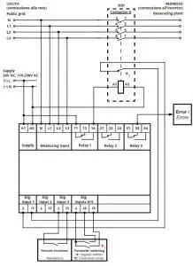 | |
| Applies to: » CEI 0-21:2019 | *1 … Parameter switching: • definitive mode (Operational mode 0): I4 inactive / contact opened:over frequency 1, under frequency 1 I4 active / contact closed: overfrequency 2, underfrequency 2 • transitory mode (Operational mode 1): I5 active / contact closed: over frequency 2, underfrequency 2 I5 inactive / contact open: overfrequency 3, underfrequency 3 *2 … Auxiliary contact configurable as “normally open”, “normally closed” or “disabled” |
| TELE Haase Steuergeraete Ges.m.b.H. Vorarlberger Allee 38 AT-1230 Vienna Austria | NEED SUPPORT PLEASE CALL: +43 / 1 / 614 74-0 (CET working hours) E-MAIL: [email protected] | Subject to alterations and errors. Release 05/2020 090750A_na003-m64_en |


