![]()
User Manual
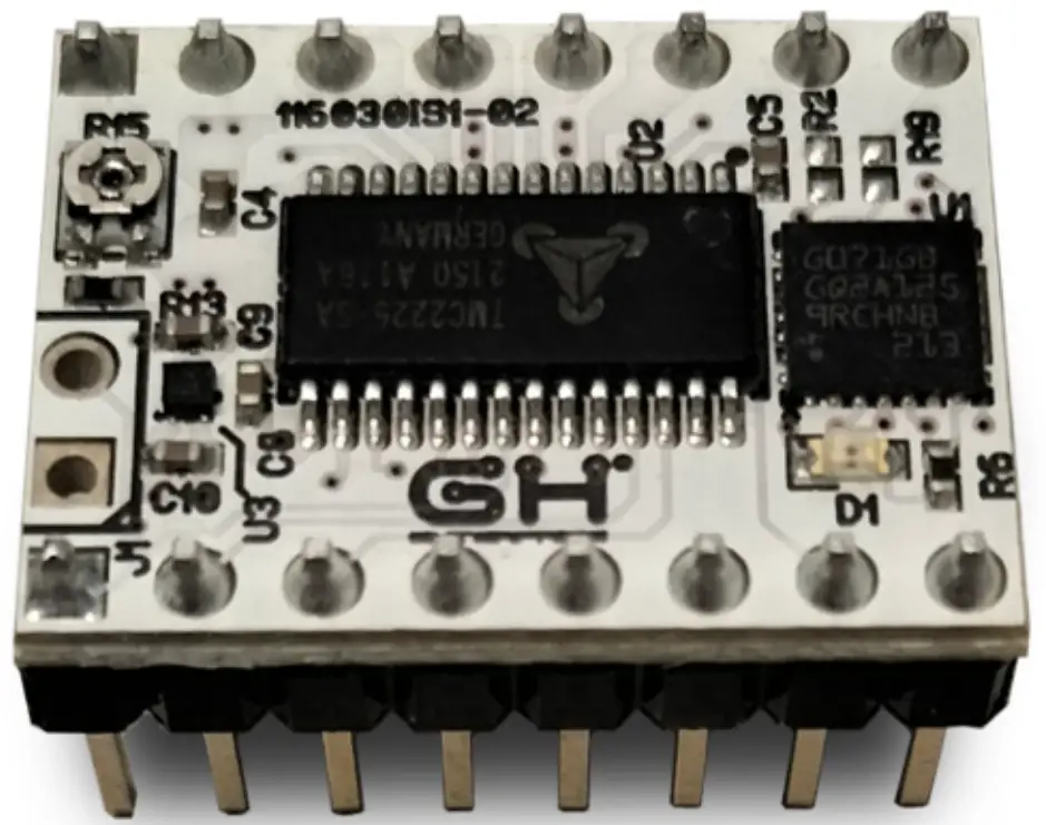
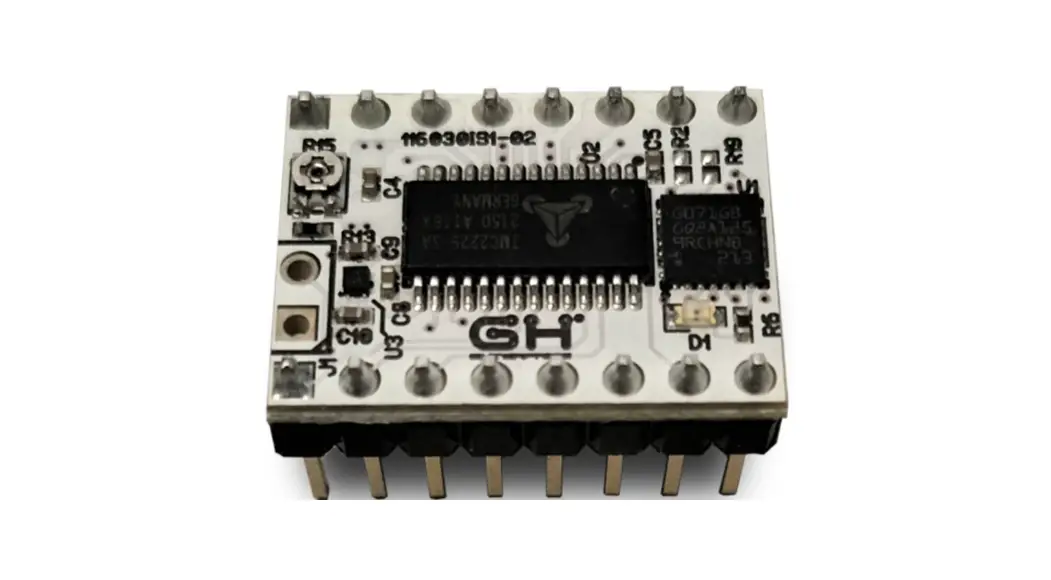
NAME: SMART SHAPER
MODEL: 116030-01
Introduction
Input shaping algorithms are designed to suppress the vibrations characterized by a particular frequency and dumping ratio.
Dumping ratio is difficult to estimate and it’s usually assumed to be 10%.
Frequency should be estimated experimentally for both axes.
The measure of the axes frequencies requires the following steps:
- Print of a reference model (see 4.1.)
- Measurement of distance between ringing peaks (see 4.2.)
- Frequency calculation by given formula (see 4.2.)
Next it will be explained how to configure the boards with the frequencies previously found and the preferred Input Shaping algorithm (see Errore: sorgente del riferimento non trovata)
Finally It will possible to print again the reference model but with Input Shaping Enabled (see 5.4.) in order to verify the correct values of frequencies and the performance of the algorithm.
Requirements
The following instructions are intended for the following setup:
- Cartesian printer
- X/Y axes driven by Smart Shaper Boards
- X/Y axes resolution 80 steps/mm
- TMC2225 configured with 16 microsteps resolution and interpolation
- TMC2225 configuration can be done via UART or bootstrap pins.
Hardware
3.1. TMC 2225 Driver Specifications
- TMC2225-SA stepper motor controller & driver
- Supply voltage 5.5-36V
- Continuous Iphase = 1.4ARMS
- Iphase up to 1.77ARMS = 2,5Apeak for a short time
- Quiet operation with StealthChop
- Sensorless homing with StallGuard
- Energy saving with CoolStep
- Configuration and extended diagnostic via UART
- Control via Step&Dir interface
- Board width 0.6”. board height 0.8”
- 2×8 pin 0.1” head rows for pins/connectors
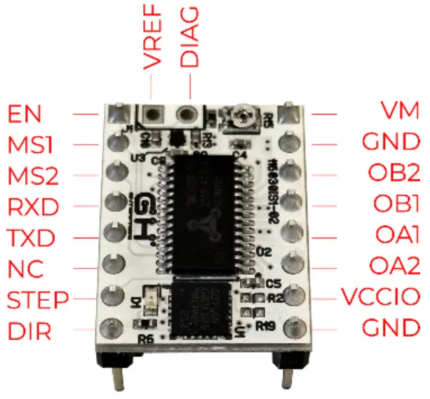
3.2. Pinout
| Power Supply | |
| GND | Ground |
| VM | Motor Supply Voltage 5.5V-36V |
| VCCIO | Logic Supply Voltage 3V-5V |
| Motor Outputs | |
| 0A2 | Motor Coil 1 |
| 0A1 | Motor Coil 1 |
| OB1 | Motor Coil 2 |
| 0B2 | Motor Coil 2 |
| Control Inputs | |
| STEP | STEP input (internal pull-down resistor) |
| DIR | DIR input (internal pull-down resistor) |
| TMC2225 | |
| EN | Enable Motor Outputs: GND=on, VIO=off |
| MS1 | Microsteps resolution configuration (internal pulldown resistors) MS2, MS1: 00: 14, 01:14, 10: 1/16, 11: 1/32 |
| MS2 | – |
| RXD | UART RX, Directly connected to the PDN |
| TXD | UART TX, Connected to the PDN via a 1K resistor on board |
| DIAG | Diagnostic output. Hi level upon driver error. Reset by ENN=high. |
| VREF | Analog Reference Voltage |
3.3. Motor Current Regulation
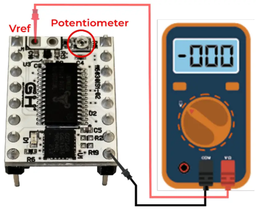
Driver motor current should match the current tolerated from your step motors. The current can be adjusted the value of VREF using the onboard potentiometer.
VREF [V]= (Irms * 2.5V) / 1.77A = Irms * 1.41 = Imax [A] The value of VREF in Volt corresponds to the value of Peak Current Imax in Ampere.
In the following picture are indicated how to measure VREF. The Smart Shaper board should be installed on the motion board and the VM power supply should be present.![]() Pay attention to avoid any short circuits when using screwdriver on potentiometer
Pay attention to avoid any short circuits when using screwdriver on potentiometer
3.4. Dissipation recommendation
TMC2225 if not well cooled goes in to thermal protection state and stops to work. It’s highly recommended to:
- Install the Heat Sinks provided with installation set
- Use a 3D motion control board equipped with a cooling fan system.
Resonance Frequency Measurement
4.1. Print Calibration Model
The calibration model prepared for frequency estimation consists in a simple L Model printed with the walls aligned along X and Y axes.
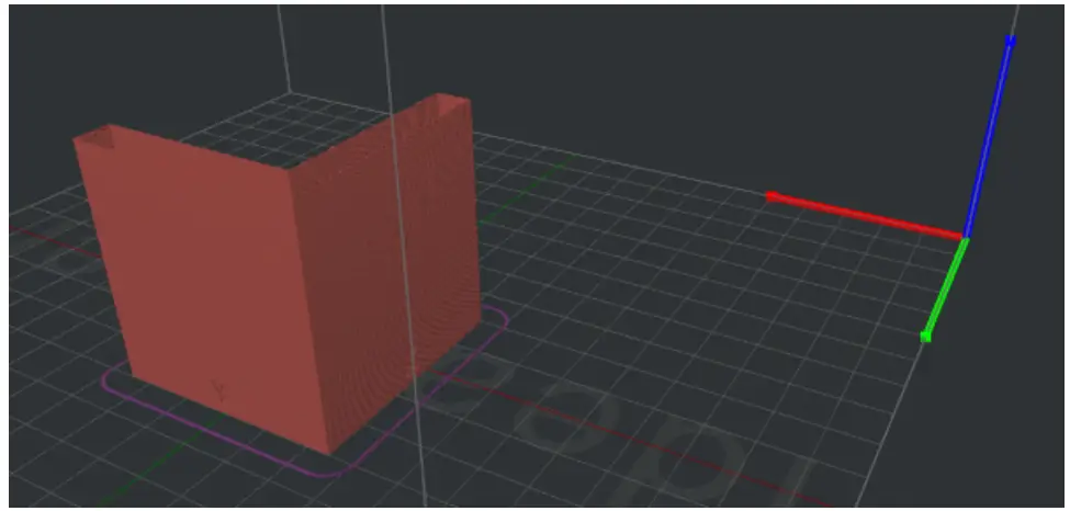
The printed part has one wall marked with X label and another one marked with Y label.
The X Label is on the wall aligned along the Y axes and the Y Label is on the wall aligned along the X axis. The reason is that the ringing due to Y acceleration/deceleration are visible on X axis and vice-versa.
The walls are printed at 100 mm/s. Acceleration is linearly increased from 500 mm/s2 (Bottom) to 18000 mm/s2 (Top) in order to increase the vibrations.
TMC2225 is configured in current mode to support high acceleration through G-code sequence.
X and Y Coordinates will not exceed 145 mm.
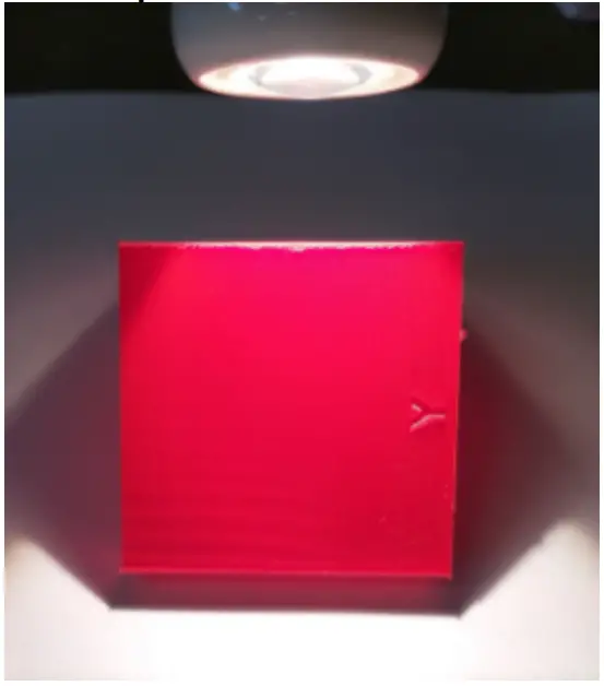
Material should be PLA (using a red color improves the measurement of ringings) and nozzle diameter 0.4 mm.
Print the model. It’s possible that at some height the printer start to loose steps because acceleration is too high to be tolerated by mechanics. If it happens just stop the printer. Now extract the printed part from the printer and analyze it.
4.2. Frequency Measurement
To find the ringing frequency it should be measured the distance between two peaks of the oscillations.
The easiest way is:
- put the part under a light beam parallel to the surface

- mark each visible oscillation peaks
- measure with a caliper the total distance D in mm between the first mark and last mark

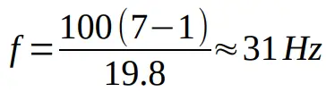
- calculate the oscillation frequency (Hz) using the formula where
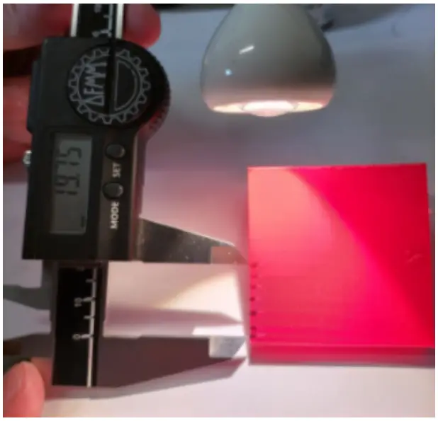
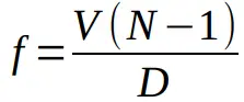
- V =100 mm/s
- N is the number of marks
Example of a Y axis oscillation frequency measurement.
We marked 7 oscillation peaks. The measured distance was about 19.8 so the frequency was:
Boards Configuration
5.1. G-Code Generator
The G-Code generator is in two versions, one in spreadsheet to download and one online version, on the GH Enterprise web site ( https://gh-enterprise.com/en/3d-printercontroller/)

5.2. G-Code configuration sequence
Each Smart Shaper board can be programmed via a specific G-Code sequence generated by the spreadsheet Smart Shaper G Code Generator.ods (see 5.3.).
An example of such sequences can be found in the file Smart Shaper Calibration. gcode (lines 32-129). In this case they have been inserted two sequences, one for X driver and one for the Y driver, that DISABLE the Input Shaping filter to detect ringings.
5.3. Sequence Generator
The spreadsheet version of Smart Shaper G Code Generator. ods is the tool to generate the G-Code configuration sequence.
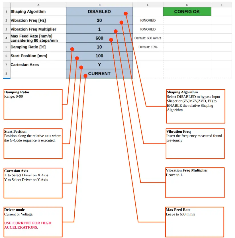
Open the spread sheet and fill all the fields as indicated in the picture. Check that configuration is valid (Config OK green label).
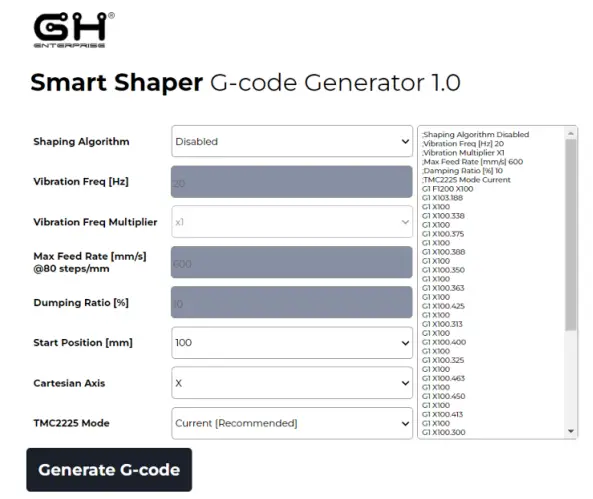
The web version of Smart Shaper G Code Generator, the same sequence to generate the G-Code configuration of the spreadsheet version.
5.4. Print with Input Shaping
Generate a G-Code configuration sequence for each axis according to the measured frequencies.
![]() Due to the high accelerations of Calibration Model, the TMC2225 SHOULD BE CONFIGURED IN CURRENT MODE.
Due to the high accelerations of Calibration Model, the TMC2225 SHOULD BE CONFIGURED IN CURRENT MODE.
Replace the two original sequences in the Smart Shaper Calibration.gcode (lines 32-129) with the new generated ones. Print the modified G-Code.
Just after homing procedure the two configuration sequence will be executed.
5.5. Status Led Information
A red led is placed on each Smart Shaper board. The blinking frequency provide some information about the board.
Just after the startup the Led will blink as many times related to the version of the installed firmware (Ex. Firmware is 1.3 will blink 3 times).
After startup the Led will indicate the current status of the board as shown in the following table.
| Frequency (Hz) | Meaning |
| 0.5 | Input Shaper Off |
| 1 | Input Shaper On |
| 2 | Configuration Failed (wrong parameters) |
| 4 | Input Step Rate too high |
Led can be used to verify that the configuration has been correctly received and processed by the board.
![]()
Smart Shaper
116030 Smart Shaper User Manual V1-03
GH enterprise s.r.l. Via Tolosano, 8 – ZIP: 48018 – Faenza (RA) – Italy


