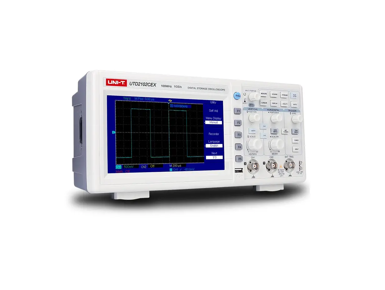
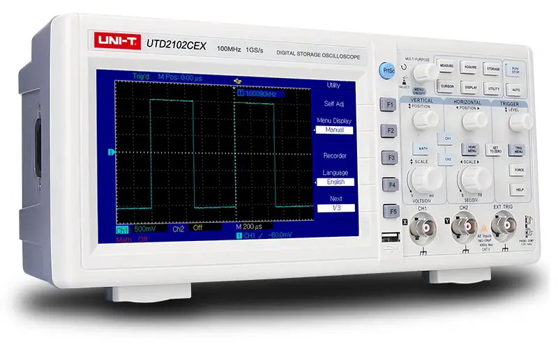
UNI-T UTD2000CEX-Digital Oscilloscope Voltage Meter
Version
| Version | Modified Item |
| V1.0 | Official version |
| V1.1 | Add table definitions for each code in the appendix; Add the description of typical case |
| V1.2 | Improved the description of capture waveform command |
| V1.3 | Improved the description of channel switch and trigger level |
Statement
- All the command of file must issue by interface UCI of uci.dll, the detailed description refer to UCI Help Document.pdf
- All the character instruction is not case-sensitive
- UCI interface
[C:DSO][D:DSO-X][T:USB][PID:0x5537][VID:0x4348][EI:0x82][EO:0x2][CFG:1][I:0] Or use UCI interface to query device address - Connect with several similar devices, use UCI interface to query the unique device address.
Instruction Set
IDN?
Query device name
Data format :display name %internal information #SN serial number
Data size : 50Bytes
For example:
UTG2102CEX%**#SN005
Communication Protocol Version
Query the version number of system information, to check whether the protocol interface is support.
| Command Name | Command Parameter | Command Parameter Type |
| CVer?; | none | none |
Example:
“CVer?;”
Interface:
Use interface uci_Read to read data。
Data size is 50bytes.
Data:
1,BG, 100M,1GS,2CH
Keypad
| Command Name | Command Parameter | Command Parameter Type |
| KEY | Key value | String : the abbreviation of keypad name |
| Keypad Name | Meaning |
| AT | AUTO |
| RS | RUN/STOP |
| TM | *MENU(trigger menu) |
| FC | FORCE |
| HP | HELP |
| VM | *MENU(window setting menu) |
| STZ | SET TO ZERO |
| MT | MATH |
| C1 | CH1 |
| C2 | CH2 |
| F1 | F1 |
| F2 | F2 |
| F3 | F3 |
| F4 | F4 |
| F5 | F5 |
| PS | PrScrn(screenshot) |
| MEA | Measure |
| CSR | Cursor |
| ACQ | Acquire |
| DISP | Display |
| STG | Storage |
| UTIL | Utility |
| FKN | Function Knob |
| FKNL | Function Knob Left Rotation |
| FKNR | Function Knob Right Rotation |
| VKNL | Vertical Position Knob Left Rotation |
| VKNR | Vertical Position Knob Right Rotation |
| HKNL | Horizontal Position Knob Left Rotation |
| HKNR | Horizontal Position Knob Right Rotation |
| TGKNL | Trigger Position Knob Left Rotation |
| TGKNR | Trigger Position Knob Right Rotation |
| VBKNL | Voltage Base Knob Left Rotation |
| VBKNR | Voltage Base Knob Right Rotation |
| TBKNL | Time Base Knob Left Rotation |
| TBKNR | Time Base Knob Right Rotation |
| Attribute Name | Meaning | IO | Data |
| Lock | Lock the key | W | No data |
| Unlock | Unlock the key | W | No data |
| Lock? | Query key status | R | Integer(4B): 0 – unlock; 1 – locked |
Example
“KEY:AT;”
“KEY:C1;”
“KEY:MATH;”
“KEY:FKN;” -> push
“KEY:FKNL;” -> functional knob increase
“KEY:FKNR;” -> functional knob decrease
“KEY:FKNL@lock;” -> functional knob increase - locked
Due to different device has different key name, the abbreviation is to avoid the difference!
Use local command to lock/unlock full qwerty(the same as UPO2000CS).
Command with question mark should read by interface uci_Read.
Screenshot
| Command Name | Command Parameter | Command Parameter Type |
| PrtScn | Image data format | String: bmp {BMP file} |
For Example:
BMP file: “PrtScn:bmp;”
Notes:
“PrtScn:bmp;” use interface uci_Read,buffer area size can set to 387072,read 8 bits BMP file.
Configuration Data of Read and Write
| Command Name | Command Parameter | Command Parameter Type |
| dconfig | none | none |
For Example:
“dconfig;”
Description:
Please save the file by yourself. If time-out, it can set the long timing of overtime.
Interface:
Use interface uci_Read to read data,Use interface uci_Write to write data. Read data size can set to 1024,the actual size get from returned value.
Running Status
| Command Name | Command Parameter | Data |
| Proc | Running status setup | Enum<string> : STOP/RUN/AUTO |
| Proc? | Query running status | Enum<string> : STOP/RUN/ARMD/READY/TRIGD/AUTO/SCAN/OVER/RESET { STOP/RUN/ARMED/READY/TRIGED/AUTO/SCAN/OVER/RESET } |
For Example:
query:“Proc?;”
setup:“Proc:Stop;” “Proc:AUTO;”
Notes:
The difference of “Proc:Stop”, “Proc:Run” and button “RUN/STOP”:
It is different from button function of “RUN/STOP”. Hereon “RUN” put DSO at RUN status whatever the current condition is. “STOP” is the same.
Channel Control
| Command Name | Meaning | IO | Data | Remark |
| CHSel? | query the current selected channel | R | Channel number:0/1/2/3/4 {CH1/ CH2/ MATH/ REF-A/ REF-B } | selected channel setup use:“CH:0@SEL;” |
The Basic(Common)Attribute
| Command Name | Command Parameter | Command Parameter Type | Remark |
| CH | Channel number | Start from 0 to number channel, integer value. 0:CH1;1:CH2 | Channel number is for the command to point out which channel to process |
| Attribute Name | Meaning | IO | Data |
| EN | ON/OFF | WR | Enum(Integer): 0/1{OFF/ON } |
| SEL | Select (set or query select status of the current channel) | WR | W:none {command type} R:Enum(Integer): 0/1{ON/OFF} |
| VP | Vertical position of channel | WR | Integer : position value,the middle of screen is 128,up to plus down to minus, one grid is 25. |
| HP | Pre-trigger position (horizontal adjustment) | WR | Integer : position value,the middle of screen is 350,left to plus right to minus, one grid is 50. |
| TB | Time Base(time base) | WR | W: Enum(String) : +/- {plus/minus one grid } or current value R : Double(8Bytes), current value in US unit |
| VB | Voltage Base | WR | W: Enum(String) : +/- { plus/minus one grid } or voltage value R : Double(8Bytes), power source in V unit |
| STZ | VPOS and HPos set to zero | W | none {command type} |
Support Voltage Base
| 1mV | 10mV | 100mV | 1V | 10V |
| 2mV | 20mV | 200mV | 2V | 20V |
| 5mV | 50mV | 500mV | 5V | — |
| — | 10ns | 100ns | 1us | 10us | 100us | 1ms | 10ms | 100ms | 1s | 10s |
| 2ns | 20ns | 200ns | 2us | 20us | 200us | 2ms | 20ms | 200ms | 2s | 20s |
| 5ns | 50ns | 500ns | 5us | 50us | 500us | 5ms | 50ms | 500ms | 5s | 50s |
Voltage base and the current base command written numeric value and unit directly, for example 100mv:
“CH:0@VB:100MV”,“CH:0@TB:500US;”,unit is not case-sensitive.
For Example:
Channel number:0/1/2/3/4{CH1/ CH2/ MATH/ REF-A/ REF-B }
setup:
“CH:0@EN:1@VP:128@HP:350@VB:100MV@TB:500US;”
“CH:2@EN:1;” — open MATH channel
“CH:2@VP:128;” — adjust the vertical position of MATH channel to 128
“CH:2@SEL;” — select MATH channel
query:
“CH:0@VP;”
“CH:0@TB;”
“CH:0@TBV;”
Notes:
- The command protocol of basic command and physical channel:
The command name of basic command and physical channel both use “CH”, format is “CH: channel id@Attribute:Value;” the basic command is suitable for physical channel, MATH,REF, distinguish by channel ID; - CH command and channel number should be command parameter, otherwise it be the wrong command format;
- If selected channel does not open when executing command “@SEL;” return error “channel doesn’t open”;
- If it is a physical channel(CH1/ CH2),“@VB” in fine tuning(set by “@ VD”) can only set by the way of “Enum(String) : +/- {plus/minus one grid }”, get the actual voltage base information from command “@VB”.
Physical Channel
| Command Name | Command Parameter | Command Parameter Type | Remark |
| CH | Channel number | Start from 0 to number channel, integer value | Channel number is for the command to point out which channel to process |
| Attribute Name | Meaning | IO | Data |
| CP | Coupling(channel coupling) | WR | Enum(String): D/A/G{DC/AC/GND} |
| BW | BW limit(bandwidth limit) | WR | Enum(String): Enum(Integer): 0/1{ON/OFF} |
| VD | Volts/Div(coarse/fine tuning of amplitude) | WR | Enum(String): C/F{Coarse/Fine} |
| Probe | Probe(probe ratio) | WR | Enum(Decimals): 1/10/100/1000 |
| Invert | Invert(inverse) | WR | Enum(Integer): 0/1{ON/OFF} |
For Example:
“CH:0@CP:D@BW:0@VD:C@Probe:1@invert:0;”
Notes:
- “CH:0;” this is an invalid command,selected channel should use command “CH:0@SEL;”
- Read attribute, buffer area is 10 bytes at least, return character string, coding format of character string is based on compiler. If it is UNICODE, return character string of UNICODE coding.
Frequency Meter
| Command Name | Command Parameter | Command Parameter Type | Remark |
| cmeter | — | — | — |
| Attribute Name | Meaning | IO | Data |
| EN | Enable(on/off) | WR | Enum(Integer<2Bytes>): 0/1 |
| Freq? | Frequency value | R | Double<8Bytes>, in Hz unit |
For Example:
“cmeter@en:1;”
“cmeter@freq?;” – read frequency value
Notes:
- Frequency meter measure the channel frequency that is corresponding to trigger source.
- Frequency meter is hardware measurement; the accuracy is higher than frequency parameter measurement in parameter measurement.
Parameter Measurement
| Command Name | Command Parameter | Command Parameter Type | Remark |
| Mea | See the follow table | Character string |
| Command Parameter | Meaning | IO | Data | |||
| all | Packaging read measured parameter | R | Data see MeasureParamPacket_UTD2000CEX, or use the way below, read measured parameter alone | |||
| All? | Packaging read measured parameter | R | Read united data MeasureDataPacket: Structure of all oscilloscope. Data See | |||
| freq | Freq | R | Double<8Bytes> | |||
| Cycle | Cycle | R | Double<8Bytes> | |||
| rtime | Rise | R | Double<8Bytes> | |||
| ftime | Fall | R | Double<8Bytes> | |||
| pwidth | +Width | R | Double<8Bytes> | |||
| nwidth | -Width | R | Double<8Bytes> | |||
| oshoot | Overshoot | R | Double<8Bytes> | |||
| pshoot | Preshoot | R | Double<8Bytes> | |||
| pduty | +Duty | R | Double<8Bytes> | |||
| nduty | -Duty | R | Double<8Bytes> | |||
| avg | Average | R | Double<8Bytes> | |||
| vpp | Peak | R | Double<8Bytes> | |||
| rms | RMS | R | Double<8Bytes> | |||
| high | High | R | Double<8Bytes> | |||
| low | Low | R | Double<8Bytes> | |||
| mid | Middle | R | Double<8Bytes> | |||
| max | Max | R | Double<8Bytes> | |||
| min | Min | R | Double<8Bytes> | |||
| amp | Amplitude | R | Double<8Bytes> | |||
| Attribute Name | Meaning | IO | Data |
| src | Measurement source | WR | Enum(Integer<2Bytes>): 0/1 {CH1/CH2} |
For Example:
“mea:freq;” — read frequency value;
“mea:all;” — packaging read measured parameter
“mea:all?;” — packaging read all measured parameters(common)
“mea@src:0;” — set measurement source as CH1;
Code Example:
Read parameter alone:
double dv = 0.0;
r = uci_ReadX(m_session, _T(“mea:freq”), 1000, (byte*)&dv, sizeof(dv));
if (UCISUCCESS(r)) {
printf(“Freq = %f”, dv);
}
Packaging read all parameters:
namespace cb = comAPICommon;//comAPICommon alias
void Test_MeasureParams_DSO() {
comAPICommon::MeaValue params[50];
auto r = uci_ReadX(m_session, _T(“mea:all?;”), 2000, (byte*)params, sizeof(params));
ASSERT(r >= 0);
PrintMeasureParams(params);
};
void PrintMeasureParams(comAPICommon::MeaValue* _p) {
void PrintMeasureParams(comAPICommon::MeaValue* _p) {
printf(“\n+++++++++++++++++++++++++++++++++++++++++++++++++++\n”);
PrintMeaParam(_p[cb::MP_FREQ], “freq”);
PrintMeaParam(_p[cb::MP_PERIOD], “period”);
PrintMeaParam(_p[cb::MP_NDUTY], “NDUTY”);
PrintMeaParam(_p[cb::MP_PDUTY], “PDUTY”);
PrintMeaParam(_p[cb::MP_MAX], “MAX”);
PrintMeaParam(_p[cb::MP_MIN], “MIN”);
PrintMeaParam(_p[cb::MP_PKPK], “VPP”);
PrintMeaParam(_p[cb::MP_RMS], “RMS”);
PrintMeaParam(_p[cb::MP_OVERSHOOT], “OVERSHOOT”);
PrintMeaParam(_p[cb::MP_PRESHOOT], “PRESHOOT”);
PrintMeaParam(_p[cb::MP_AMP], “AMP”);
PrintMeaParam(_p[cb::MP_RISE_TIME], “RISE_TIME”);
PrintMeaParam(_p[cb::MP_FALL_TIME], “FALL_TIME”);
printf(“\n—————————————————-“);
}
void PrintMeaParam(const comAPICommon::MeaValue& _p, const char * _name) {
printf(“%s = “, _name);
if (_p.IsExist) {
if (_p.IsValid) {
printf(“%f “, _p.Value);
} else {
printf(“–“);
}
} else {
printf(“NotExit”);
}
printf(” %s%s\n”, unit::uci_UnitFindScaleName(_p.Unit.Scale),
unit::uci_UnitFindTypeName(_p.Unit.Type));
}
The structure and description of MeaValue see: MeasureDataPacket
Capture Waveform Data
| Command Name | Command Parameter | Command Parameter Type |
| Capture wave | Waveform format | String:.bin /.csv/.sav {binary system data/CSV file/built-in waveform file in oscilloscope} |
| Command Name | Command Parameter | Command Parameter Type |
| Capture wave | Waveform format | String:.bin /.csv/.sav {binary system data/CSV file/built-in waveform file in oscilloscope} |
For Example:
“capture wave:.bin@CH:0@DT:AD;” — read waveform data of CH1, AD value
“capture wave:.bin@CH:0@DT:vol;” — read waveform data of CH1, voltage value
“capture wave:.csv@CH:0@DT:vol;” — read waveform data of CH1, voltage value, keep in CSV file
(only use uci_ReadToFileX)
“capture wave:.sav@CH:0;” — read waveform data of CH1 (.sav file)
Description:
- “.bin” and ”.csv“ file must include:@CH:0” and“@DT:”attribute,and ”.sav” file must include @CH:0 attribute;
- This waveform data is the initial data, not display data((there are only a few hundred points),it can use in
waveform analysis task; - It can use read parameter interface{uci_Read or uci_ReadX}or read file interface{uci_ReadToFile or uci_ReadToFileX},
the former keep data in buffer are of in-memory, the latter keep data in hard disk file(if it is UCI_DEMO.EXE
program,please correct the corresponding suffix name.) - When use read interface uci_ReadX:
“capture wave:.bin@CH:0@DT:AD;” received the buffer area size of data:≥64000Bytes
“capture wave:.bin@CH:0@DT:vol;” received the buffer area size of data:≥128000Bytes
“capture wave:.sav@CH:0;” received the buffer area size of data:≥64000Bytes
Notes:the final actual valid data size, it confirmed by interface uci_ReadX returned value. - sav file is belong to internal format; it can open by waveform analysis of upper computer or parse by protocol.
- Waveform data format:
a) AD value : 16 bits short type, a waveform point of waveform data;
b) VOL value,that is voltage value, zero point based on channel base line
Trigger System
| Command Name | Command Parameter | Command Parameter Type | Remark |
| trig | — | — | — |
| Attribute Name | Meaning | IO | Data |
| t | Type | W | Enum(String) : E/V /P{ EDGE/VIDEO/PLUSE WIDTH } |
| src | Trigger source | W | Enum(String) : c1/c2 /ext/ac/alt{ CH1/CH2/EXT/AC LINE/ALTER } |
| mode | Trigger mode | W | Enum(String) : A/ N /S{ AUTO/NORMAL/SINGLE } |
| cp | Trigger coupling | W | Enum(String) : D/A/H/L { DCl / AC /H Restrain /L H Restrain } |
| pos | Trigger mode | W | Ingeger<2Bytes>: zero point based on channel base line,up to positive down to negative, each grid is 25; |
| st | Edge trigger slope type | W | Enum(String) : F / R /A{ Fall / Rise/Rise and Fall } |
For Example:
“trig@t:e;” — set trigger type as edge trigger;
“trig@pos:25;” — set trigger level higher one grid than base line, if voltage base is 1V, then trigger voltage is
1V;
(If need to set voltage value of trigger level, convert it as the above-mentioned by yourself)
【Basic】 Written Parameter
Parameter address in this command is digital coding; it need refer to the command coding definition in file comApiDef.h This command is to compatible the old protocol.
| Command Name | Command Parameter | Command Parameter Type | Remark |
| wp | — | — | — |
| Attribute Name | Meaning | IO | Data |
| CH | Channel number | W | Enum(Integer<2Bytes>): 0/1 {CH1/CH2} |
| addr | Parameter address(command number) | W | See definition CONTROL_CMD in file comApiDef.h |
For Example:
“WP@CH:0@ADDR:950:;” — set DISPLAY parameter
Notes:
“@CH” and “@addr” must use at the same time
【Basic】 Read Parameter
Parameter address in this command is digital coding; it need refer to the command coding definition in file comApiDef.h This command is to compatible the old protocol.
| Command Name | Command Parameter | Command Parameter Type | Remark |
| rp | — | — | — |
| Command Name | Command Parameter | Command Parameter Type | Remark |
| rp | — | — | — |
For Example:
“RP@CH:0@ADDR:951:;” — read DISPLAY parameter
Notes:
“@CH” and “@addr” must use at the same time
Case
Measure signal frequency and amplitude parameter
Method
- Use parameter measure function to test signal, including frequency, amplitude, cycle etc. The detailed see Measure function: Parameter measurement
- Use UTILITY->frequency meter to test signal frequency:Frequency Meter
Difference:
- MEASURE is software measurement, frequency meter is hardware measurement, frequency meter test accuracy is higher;
- Frequency meter test the signal source that is the corresponding signal of trigger source; parameter measurement test signal source that is source only can set in parameter measurement.
After the trigger channel is triggered, capture waveform data of the channel that is to be tested, and then deep analysis
For example:CH1 is the signal test channel which to connect with test source. CH2 is the trigger channel which to connect with trigger signal, it is usually user-defined. The aim is to find trigger timing, to capture waveform block in CH1 in corresponding time, subtract data and then analyze it.
Common model:
- trigger mode set as single trigger, command:“trig@mode:s;”(use write parameter interface);
- running status as RUN,command:“proc:run;” (use write parameter interface);
- get running status, check running status whether is STOP, if it is STOP, that is means it’s been triggered, command “proc?”(use read and write interface)
- If it has been triggered, subtract waveform data, command:“capture wave:.bin@CH:0@DT:vol;” Repeat 2-4 steps to complete this model.
Appendix
MeasureParamPacket
typedef struct _measure_param {
float value;
int unit;
}MeasureParam;
typedef struct
{
MeasureParam freq;
MeasureParam period;
MeasureParam risetime;
MeasureParam falltime;
MeasureParam pwidth;
MeasureParam nwidth;
MeasureParam overshoot;
MeasureParam preshoot;
MeasureParam pduty;
MeasureParam nduty;
MeasureParam vmean;
MeasureParam vpp;
MeasureParam vrms;
MeasureParam vtop;
MeasureParam vbase;
MeasureParam vmid;
MeasureParam vmax;
MeasureParam vmin;
MeasureParam vamp;
//
char Reserve[24];
}MeasureParamPacket_UTD2000CEX;
MeasureDataPacket
Code Definition
Data packet is MeaValue mp[50] (400Bytes), that is fixed 50 test parameter in one dimensional sequence. EMeaParam
defines the position of each parameter in the sequence.
struct UnitParam {
char Type; //unit type,like Time,Freq etc.,define by EType
char Scale; //magnitude,like k、n,p,M etc.,define by EScale
};
//@brief : physical quantity value
//@remark: 4Byte align -> 8Bytes
struct MeaValue {
float Value;
UnitParam Unit;
char IsValid; //whether is valid. 0 presents invalid; 1 presents valid.
char IsExist; // whether is exist. 0 presents existence; 1 presents absent.
};
Definition of In-memory Table
Each parameter takes 8 bits, 50 parameter space, and 400 bytes in total.
In-memory model of each parameter
Each parameter takes 8 bits, 50 parameter space, and 400 bytes in total.
In-memory model of each parameter:
| Fields | Value | Unit.Type | Unit.Scale | Is Valid | Is Exist |
| Byte | 4Bytes | 1Byte | 1Byte | 1Byte | 1Byte |
| Meaning | Physical value(decimal) | Unit type coding | Unit quantity coding | Whether is valid | Whether is existence |
| Data | Value | Value | 0:invalid;1:valid | 0:absent; 1: existence |
Encoding Physical Unit
Code Definition
enum EScale : char {
SCALE_p = -4,
SCALE_n,
SCALE_μ,
SCALE_m,
SCALE_STD = 0,
SCALE_K,
SCALE_M,
SCALE_G,
SCALE_T,
};
enum EType : char {
TYPE_INVALID = -1,
TYPE_FREQ,
TYPE_TIME,
TYPE_AREA, //area (Vs)
TYPE_SAMPLERATE,//sampling rate(Sa/s)
TYPE_POINT, //count(Sa)
TYPE_VPP, //peak-to-peak value
TYPE_VOLTAGE,//voltage
TYPE_CURRENT,//current
TYPE_DB, //DB
TYPE_VV, //
TYPE_PERCENT,//percentage
TYPE_DEGREE, //degree
TYPE_WATT, //watt,power
TYPE_UNKNOWN,// unknown unit
};
Coding table
Unit Coding:
| Unit | Coding |
| p | -4 |
| n | -3 |
| μ | -2 |
| m | -1 |
| Standard unit | 0 |
| K | 1 |
| M | 2 |
| G | 3 |
| T | 4 |
Unit Type Coding:
| Unit | Coding |
| p | -4 |
| n | -3 |
| μ | -2 |
| m | -1 |
| Standard unit | 0 |
| K | 1 |
| M | 2 |
| G | 3 |
| T | 4 |
Parameter Coding
Coding Definition
//@brief : the common definition of parameter measurement data packet
//@remark:
enum EMeaParam {
MP_MAX = 0, //maximum value
MP_MIN, //minimum value
MP_HIGH, //High(Top)-high level(top value)
MP_MIDDLE, //Middle value
MP_LOW, //Low(Bottom) – lower level(bottom value)
MP_PKPK, //VPP-peak-to-peak value
MP_AMP, //amplitude
MP_MEAN, //mean value
MP_CYCMEAN, //
MP_RMS, //root mean square
MP_CYCRMS, //cycle root mean square
MP_AREA, //area
MP_CYCAREA, // cycle area
MP_OVERSHOOT,//overshoot
MP_PRESHOOT, //preshoot
MP_PERIOD, //period
MP_FREQ, //frequency
MP_RISE_TIME,//rise time
MP_FALL_TIME,//fall time
MP_PWIDTH, //positive pulse width
MP_NWIDTH, //negative pulse width
MP_PDUTY, //positive duty ratio
MP_NDUTY, //negative duty ratio
MP_RISEDELAY,//rise delay
MP_FALLDELAY,//fall delay
MP_PHASE, //phase
MP_FRR, //
MP_FRF,
MP_FFR,
MP_FFF,
MP_LRF,
MP_LRR,
MP_LFR,
MP_LFF,
MP_BURST_WIDTH, //burst
//
//reserve section
//
//fixed 50 parameters
MP_MAX_COUNT = 50,
};
Coding Table
| Parameter | Coding |
| Maximum value | 0 |
| Minimum value | 1 |
| High level/ top value (High/Top) | 2 |
| Middle value | 3 |
| High level/bottom value(Low) | 4 |
| Peak-to-peak value(PKPK) | 5 |
| Amplitude(AMP) | 6 |
| Mean value(MEAN) | 7 |
| Cycle mean(Cycmean) | 8 |
| Root mean square(RMS) | 9 |
| Cycle root mean square(Cycrms) | 10 |
| Area(AREA) | 11 |
| Cycle area(Cycarea) | 12 |
| Overshoot | 13 |
| Preshoot | 14 |
| Cycle | 15 |
| Frequency(Freq) | 16 |
| Rise Time | 17 |
| Fall Time | 18 |
| Positive pulse width(PWidth) | 19 |
| Negative pulse width(NWidth) | 20 |
| Positive duty ratio(PDuty) | 21 |
| Negative duty ratio(NDuty) | 22 |
| Rise delay | 23 |
| Fall delay | 24 |
| Phase | 25 |
| FRR | 26 |
| FRF | 27 |
| FFR | 28 |
| FFF | 29 |
| LRF | 30 |
| LRR | 31 |
| LFR | 32 |
| LFF | 33 |
| Burst(Burst Width) | 34 |
| Reserved | 35~39 |
Notes:
- This model only support a part of parameter in the above table;
- Different definition name in C#Interface,put it in the name space ucics.unit and ucics.mea.
Data Unit Table
| Unit | Coding |
| null | 0 |
| ps | 1 |
| ns | 2 |
| μs | 3 |
| ms | 4 |
| ks | 5 |
| nVs | 7 |
| μVs | 8 |
| mVs | 9 |
| μV | 11 |
| mV | 12 |
| V | 13 |
| kV | 14 |
| pHz | 18 |
| nHz | 19 |
| μHz | 20 |
| mHz | 21 |
| Hz | 22 |
| KHz | 23 |
| MHz | 24 |
| GHz | 25 |
| mVV | 52 |
| VV | 53 |
| KVV | 54 |
| mDB | 80 |
| DB | 81 |
| KDB | 82 |
Uni-Trend Technology (China) Co., Ltd.