![]()
SIN-4-2-20 Zigbee OnOff Lighting Relay Switch
User Guide
ZIGBEE ON/OFF LIGHTING RELAY SWITCH
Reference: SIN-4-2-20
Power supply: 230V AC ~ 50Hz
Switching capabilities: 230V AC – 2 x 3A
Consumption: <1W
Maximum output power: 2 x 690W – Integrated zero crossing
RF Protocol: Zigbee 3.0
Radio frequency range: 2.4Ghz
RF power max: +10dBm
Range: up to 30m indoor
Operational temperature: -20°C to 60°C
Protection rating: IP 20
Dimensions: 40 mm (l) x 44 mm (L) x 16.9 mm (h)
Weight: 34 g
Warranty: 2 years
USE CAUTIONS
Never use the device if it is not correctly installed and placed inside a connecting box in conformity with the current norms.
• Keep the product far away from liquids.
DETAILED USER GUIDE Directly access the detailed user guide on the Support section on www.nodon.fr/en/support/Zigbee-on-off-lighting-relay switch
CONTACT
NodOn SAS 121 rue des Hêtres
45590 St CYR EN VAL (FRANCE)
SAV
www.nodon.fr/en “support” section
[email protected]
APPROVALS AND CERTIFICATIONS
![]() Hereby, NodOn SAS declares that this radio equipment conforms to the RED directive 2014/53/UE. The integral text of the EU declaration of conformity is available at the following online address: www.nodon.fr ”support” section.
Hereby, NodOn SAS declares that this radio equipment conforms to the RED directive 2014/53/UE. The integral text of the EU declaration of conformity is available at the following online address: www.nodon.fr ”support” section. The presence of this symbol on a product indicates that this one is conform to the European directive 2012/19/UE. Find out more about the provisions in force in your region regarding the separate collection of electrical and electronical devices. Respect the local rules and do not throw out the product with common domestic wastes. The correct rejection of ancient products allows preserving the environment and health.
 This product must be used indoors only.
![]() This product conforms to Zigbee radio protocol.
This product conforms to Zigbee radio protocol.
DANGER OF ELECTROCUTION![]() BEFORE ANY INSTALLATION MAKE SURE THE THE POWER SUPPLY IS DISCONNECTED TO AVOID ANY RISK OF ELECTROCUTION.
BEFORE ANY INSTALLATION MAKE SURE THE THE POWER SUPPLY IS DISCONNECTED TO AVOID ANY RISK OF ELECTROCUTION.
Directly cut the power supply from the breaker box to avoid any risk of electrocution. This relay switch is designed to be used power-up, a wrong installation can create a fire or
an electric shock. If you are not confident about electrical installation, please ask a professional. The relay switch must be installed and connected carefully following the instructions of this user guide. We will not be responsible for any loss or damage resulting from a non-respect of the instructions of this user guide. Cut the power supply before any operation and don’t do any modification if the LED is still ON.
INSTALLATION
Thanks to its small size, the Zigbee ON/ OFF Lighting Relay Switch can be installed anywhere in the wall or the ceiling (behind an existing wall switch, in a false ceiling,
TIP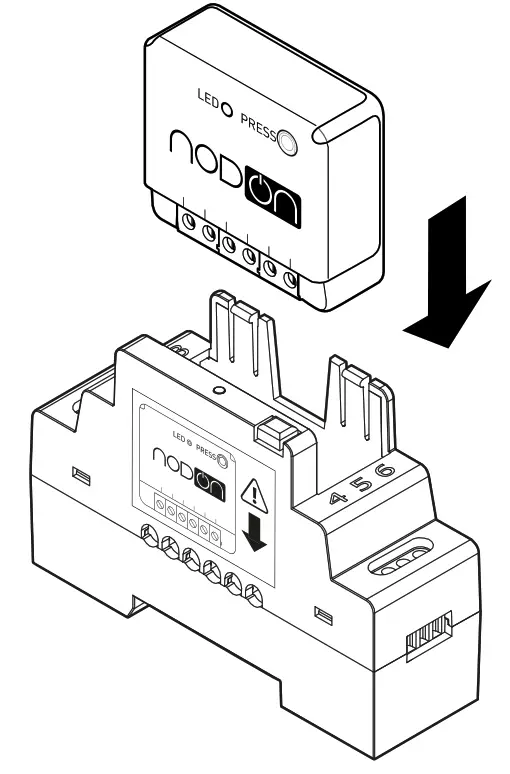 Add the Zigbee ON/OFF Lighting Relay Switch to the electric panel with NodOn DIN Rail Box*. * Optional accessory
RELAY SWITCH INPUT/OUTPUT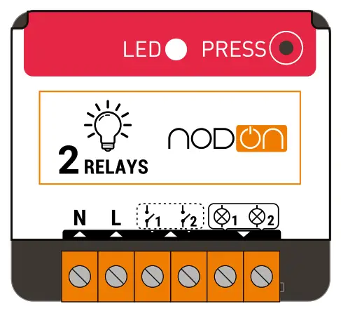
![]() – Terminal for the Neutral
– Terminal for the Neutral
– Terminal for the Line
– Input terminal – for the wired switch 1*
– Input terminal
– for the wired switch 2*
– Output 1 (controlled by½ )
– Output 2 (controlled by½ )
Each terminal should be installed with a cable from 1.5mm² to 4mm² maximum, stripped of 8mm. *Wired switch optional.
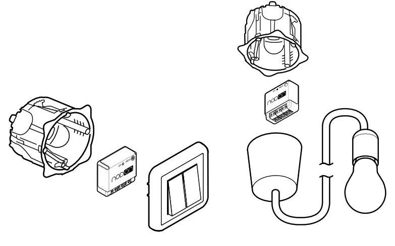
INSTALLATION DIAGRAM FOR ONE OR TWO LIGHTS
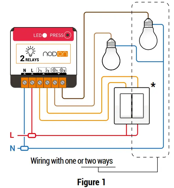
*Wired switch optional.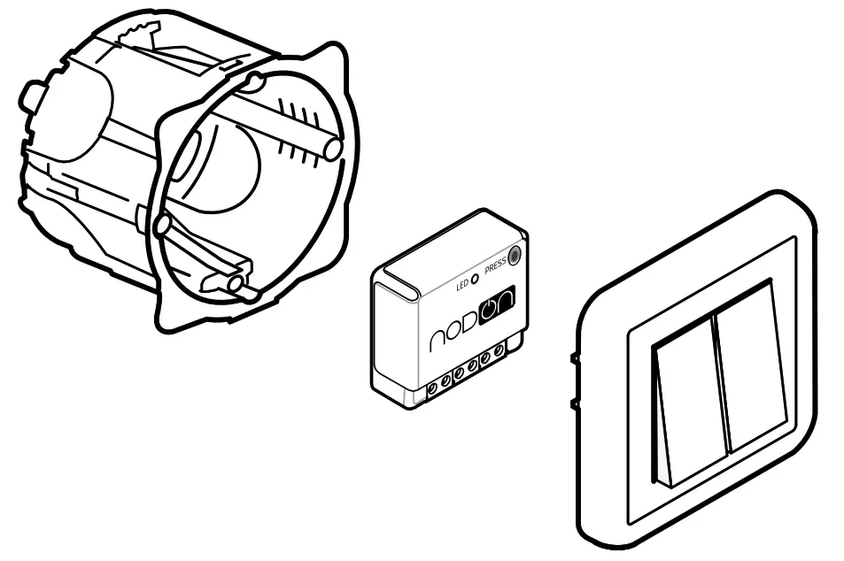
- Cut the power supply
- Dismantle the wired switch controlling the light(s) you want to connect.
- Install the ON/OFF Lighting Relay Switch according to diagram figure 1.
- Reinstall the wired switch.
- Turn the power supply back ON.
AUTO-DETECTION OF SWITCH TYPE
When you turn the power supply ON (via the electrical box for example) once the relay switch is installed, it is necessary to perform a simple action (single press on the button) on the wired switch(es). Automatic detection of the type of switch (monostable or bistable) will then be performed.
INSTALLATION DIAGRAMS
Find all the installation diagrams in the “Support” section on www.nodon.fr/en
ADDING TO A ZIGBEE NETWORK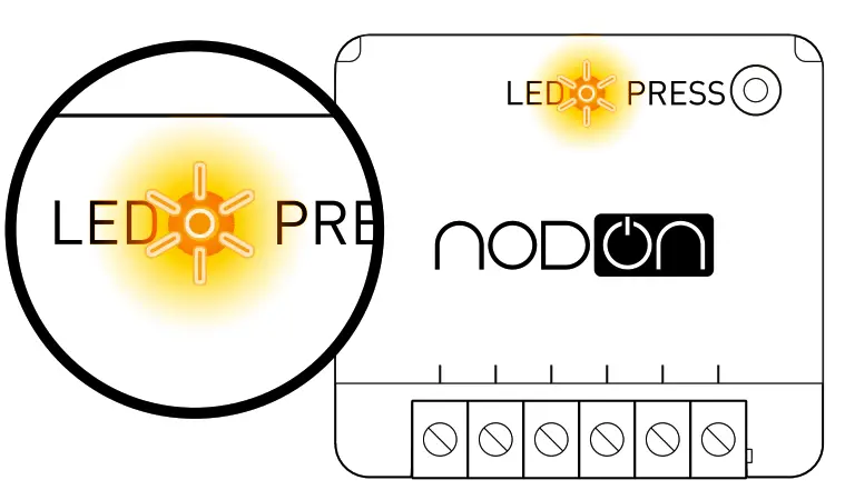
When power is turned ON, the relay switch Led will blink orange, looking to join a Zigbee network. Go to your Zigbee gateway app to activate the relay switch detection. See the compatible home automation gateways on www.nodon.fr/en/support 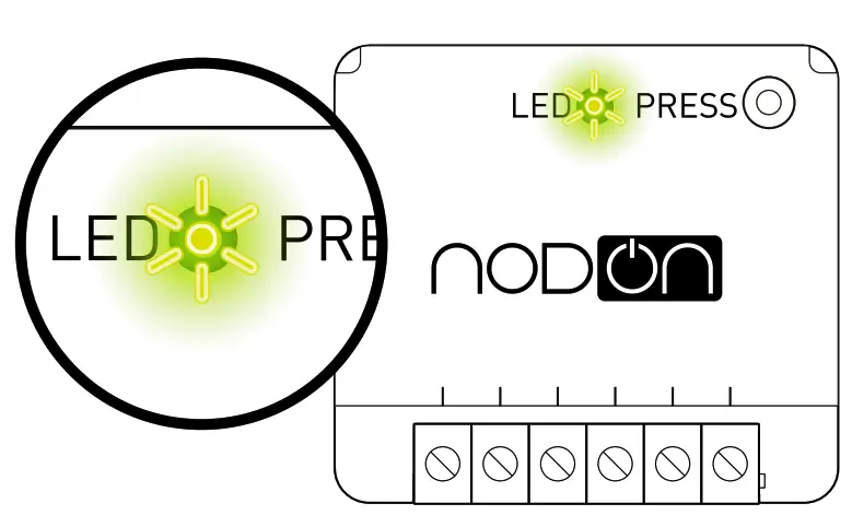
If the relay switch has correctly joined the network, the Led becomes green. The relay switch is ready for use.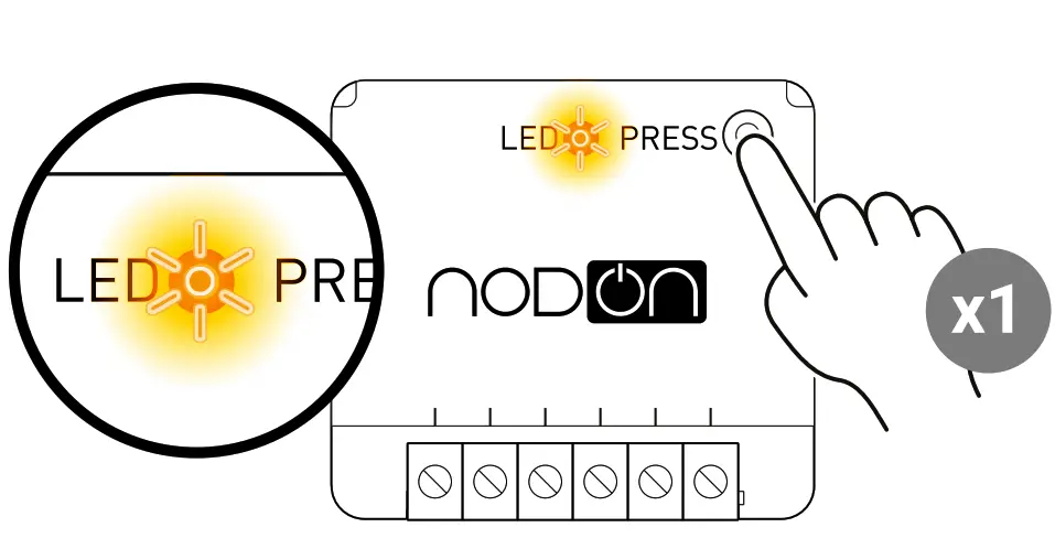
UNPAIRING PROCEDURE
To remove the module from its network, perform a Module Reset (see “Reset Procedure”).
RESET PROCEDURE
The relay switch must be power supplied.
- Press more than 5 seconds on your module’s button. The Led blinks orange.
- Press the button again (short press) to validate the reset.
- If the reset is successful, the led flashes red and green alternately then flashes orange. Repeat if necessary.
- Your module has returned to its original configuration and is ready to join a new Zigbee network.
References
 Fabricant domotique OBL - OEM - ODM pour la Maison Connectée
-
Smart Home & Building - OEM ODM OBL solutions for IoT products
-
Supports Archive - NodOn
-
Supports Archive - NodOn
-
Support technique NodOn | Documentation produit, tutoriel, cas d'usage
-
Support technique NodOn | Documentation produit, tutoriel, cas d'usage


