![]()
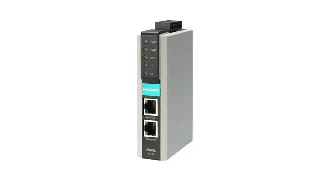
MGate 5217 Series
Quick Installation Guide
Version 1.1, January 2021
Technical Support Contact Information
www.moxa.com/support
2021 Moxa Inc. All rights reserved. P/N: 1802052170011 *1802052170011*![]()
Overview
The MGate 5217 is an industrial Ethernet gateway to bring Modbus RTU/ASCII/TCP devices to BACnet/IP network.
Package Checklist
Before installing the MGate 5217, verify that the package contains the following items:
- 1 MGate 5217 gateway
- Quick installation guide (printed)
- Warranty card
Optional Accessories:
- DK-35A: DIN-rail mounting kit (35 mm)
- Mini DB9F-to-TB Adaptor: DB9 female to terminal block adapter
- DR-4524: 45W/2A DIN-rail 24 VDC power supply with universal 85 to 264 VAC input
- DR-75-24: 75W/3.2A DIN-rail 24 VDC power supply with universal 85 to 264 VAC input
- DR-120-24: 120W/5A DIN-rail 24 VDC power supply with 88 to 132 VAC/176 to 264 VAC input by switch
NOTE Please notify your sales representative if any of the above items is missing or damaged.
Hardware Introduction
LED Indicators
| Name | Color | Function |
| PWR1 | Red | Power is being supplied to the power input |
| PWR2 | Red | Power is being supplied to the power input |
| RDY | Red | Steady: Power is on and the unit is booting up |
| Blinking: IP conflict, DHCP or BOOTP server did not respond properly, or a relay output occurred | ||
| Green | Steady: Power is on and the unit is functioning normally | |
| Blinking: Unit is responding to locate function | ||
| Off | Power is off or power error condition exists | |
| Ethernet | Amber | 10 Mbps Ethernet connection |
| Green | 100 Mbps Ethernet connection | |
| Off | Ethernet cable is disconnected or has a short | |
| P1, P2 | Amber | Serial port is receiving data |
| Green | Serial port is transmitting data | |
| Off | Serial port is not transmitting or receiving data |
Press the Reset button continuously for 5 sec to load factory defaults: The reset button is used to load factory defaults. Use a pointed object such as a straightened paper clip to hold the reset button down for five seconds. Release the reset button when the Ready LED stops blinking.
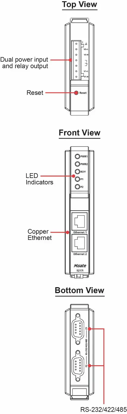
Panel Layouts
The MGate 5217 has two RJ45 Ethernet ports and two DB9 serial ports for connecting to devices.
Hardware Installation Procedure
STEP 1: After removing the MGate 5217 from the box, connect the MGate 5217 to a network. Use a standard straight-through Ethernet cable to connect the unit to a hub or switch. When setting up or testing the MGate 5217, you might find it convenient to connect directly to your computer’s Ethernet port. In this case, use a crossover Ethernet cable.
STEP 2: Connect the serial port(s) of the MGate 5217 to a serial device.
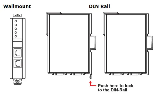
STEP 3: The MGate 5217 is designed to be attached to a DIN rail or mounted on a wall. The two sliders on the MGate 5217 rear panel serve a dual purpose. For wall mounting, both sliders should be extended. For DIN-rail mounting, start with one slider pushed in, and the other slider extended. After attaching the MGate 5217 on the DIN rail, push the extended slider in to lock the device server to the rail. The two placement options are illustrated in the accompanying figures.
STEP 4: Connect the 12 to 48 VDC or 24 VAC power source to terminal block power input.
![]() WARNING
WARNING
This product is intended to be supplied with a UL-listed power adapter or DC power source marked `L.P.S’ or `Limited Power Source’, rated 12 to 48 VDC, 510m A (min.) or 24VAC, 50/60Hz, 300mA (min.), and Tma 75°C (min.).
![]() WARNING
WARNING
The power cord adapter should be connected to a socket outlet with an earthing connection, or the power cord and adapter must comply with Class II construction.
Wall or Cabinet Mounting
Mounting the MGate 5217 Series on to a wall requires two screws. The heads of the screws should be 5 to 7 mm in diameter, the shafts should be 3 to 4 mm in diameter, and the length of the screws should be more than 10.5 mm.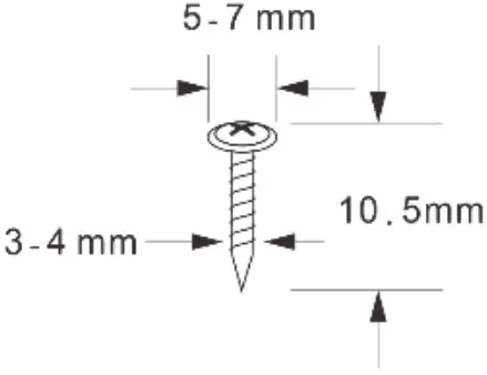
![]() WARNING
WARNING
The MGate 5217 shall be mounted at a height less than 2 meters.
Pull-high, Pull-low, and Terminator for RS-485
When you remove the MGate 5217’s top cover, you will find the DIP switches to adjust each serial port’s pull-high resistor, pull-low resistor, and terminator. Serial port1/port2 can be adjusted by SW1/SW2, respectively.
| DIP Switch | 1 | 2 | 3 | 4 |
| Pull-high resistor | Pull-low resistor | Terminator | Reserve | |
| ON | 1 kΩ | 1 kΩ | 120 Ω | Reserve |
| OFF | 150 kΩ | 150 k Ω | -* | Reserve |
Software Installation Information
You can download the User’s Manual and Device Search Utility (DSU) from Moxa’s website: www.moxa.com. Please refer to the User’s Manual for additional details on using DSU.
The MGate 5217 also supports login via a web browser.
Default IP address: 192.168.127.254
Default account: admin
Default password: moxa
Pin Assignments
Ethernet Port (RJ45)
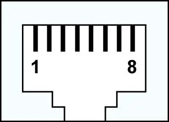
| Pin | Signal |
| 1 | Tx+ |
| 2 | Tx- |
| 3 | Rx+ |
| 6 | Rx- |
Serial Port (DB9 Male)
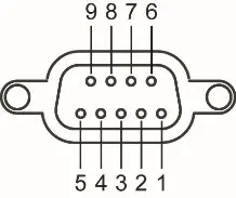
| Pin | RS-232 | RS-422/ RS-485 (4W) | RS-485 (2W) |
| 1 | DCD | TxD- | |
| RxD | TxD+ | ||
| 3 | TxD | RxD+ | Data+ |
| 4 | DTR | RxD- | Data- |
| 5 | GND | GND | GND |
| 6 | DSR | ||
| 7 | RTS | ||
| 8 | CTS | ||
| 9 |
Power Input and Relay Output Pinouts
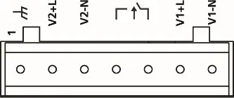
| V2+L | V2-N | V1+L | V1-N | |||
| ShieldedGround | AC/DC Power Input 2 | AC/DC Power Input 2 | Relay Output | Relay Output | AC/DC Power Input 1 | AC/DC Power Input 1 |
Specifications
| Power Requirements | |
| Power Input | 12 to 48 VDC and 24 VAC |
| Power Consumption | 24 VAC, 300 mA (max.) 12 to 48 VDC, 510 mA (max.) |
| Operating Temperature | -40 to 75°C (-40 to 167°F) |
| Storage Temperature | -40 to 85°C (-40 to 185°F) |
| Operating Humidity | 5 to 95% RH |
| Magnetic Isolation Protection (serial) | 2 kV |
| Dimensions Without ears: With ears extended: | 29 x 89.2 x 118.5 mm (1.14 x 3.51 x 4.67 in) 29 x 89.2 x 124.5 mm (1.14 x 3.51 x 4.9 in) |
| Relay Output | 1 digital relay output to alarm (normal close): current carrying capacity 1 A @ 30 VDC |
![]() WARNING
WARNING
If the battery is replaced with the wrong type, the risk of an explosion is highly likely.


