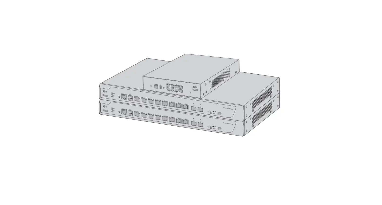
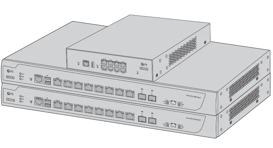
FS COM SG-3110 Multi-Service and Unified Security Gateways
Introduction
Thank you for choosing FS Gateways. This guide is designed to familiarize you with the layout of the gateway and describes how to deploy the gateway in your network.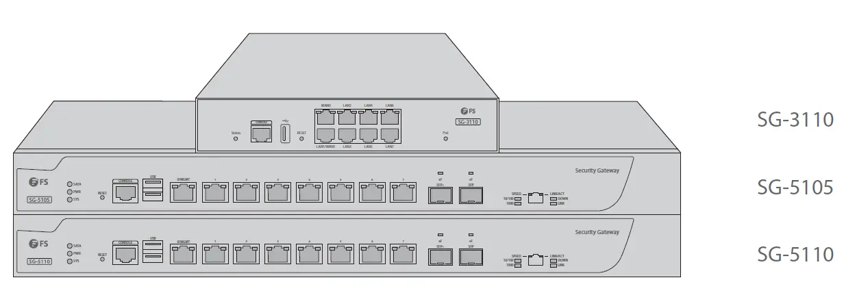
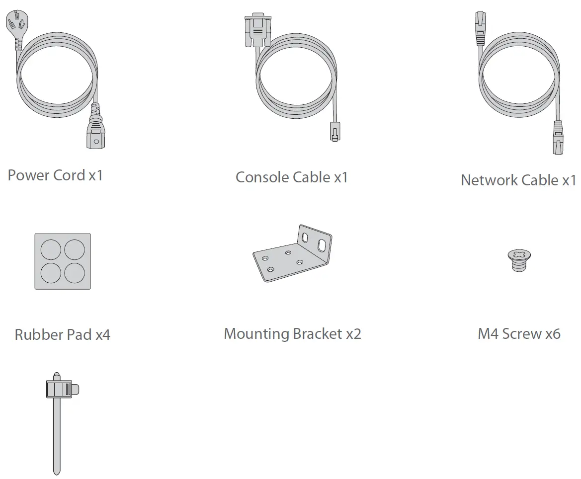
Accessories
SG-3110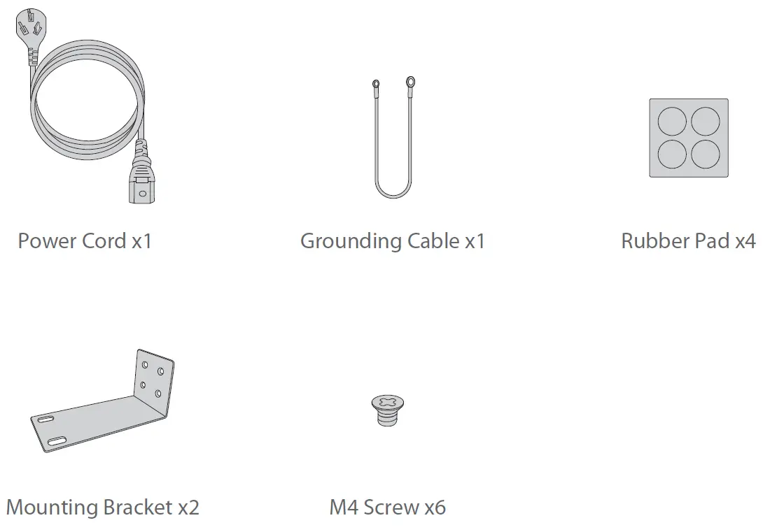
SG-5105/SG-5110
NOTE: FS gateways have dust plugs delivered with them. Keep the dust plugs properly and use them to protect idle optical ports.
Hardware Overview
Front Panel Ports
SG-3110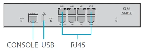
| Ports | Description |
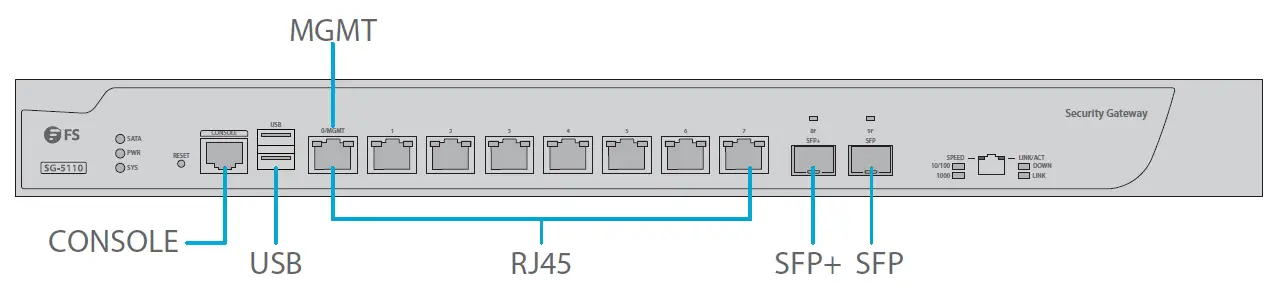
| RJ45 | 10/100/1000BASE-T ports for Ethernet connection |
| SFP | SFP port for 1G connection |
| SFP+ | SFP+ port for 10G connection |
| CONSOLE | An RJ45 console port for serial management |
| MGMT | An Ethernet management port |
| USB | A USB management port for software and configuration backup and offl ine software upgrade |
| Button | Description |
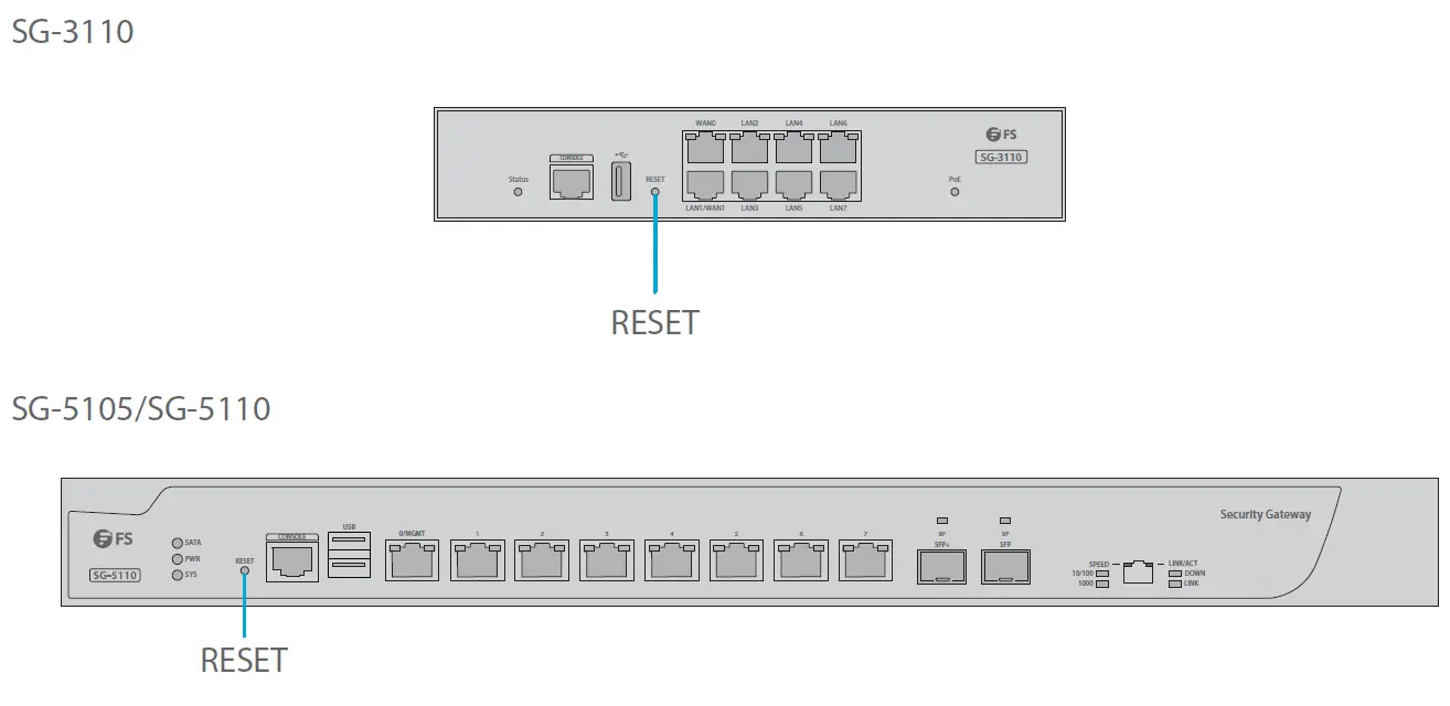
| RESET | Press and release the RESET button to restart the device. To restore to factory default, press and hold the RESET button for more than three seconds. |
Back Panels
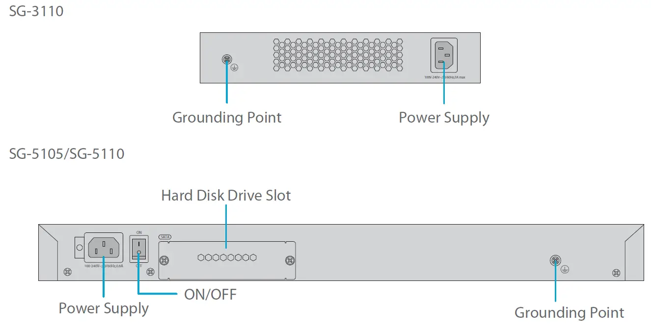
| Button | Description |
| Power ON/OFF | Control the gateway power supply. |
Front Panel LEDs
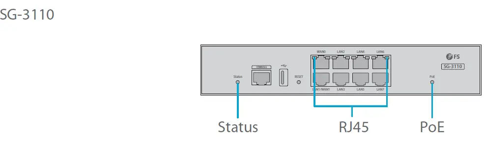
| LEDs | Status | Description |
| Status | Blinking Green | System is being initialized. |
| Solid Green | The initialization process is complete. | |
| Solid Red | The system sends out an alarm. | |
| RJ45 | Solid Green | The port is up. |
| Blinking Green | The port is receiving or transmitting data. | |
|
PoE | Solid Green | PoE works normally. |
| Red/Green Flashing Alternately | PoE overload occurs. | |
| Solid Red | An alarm is generated. |
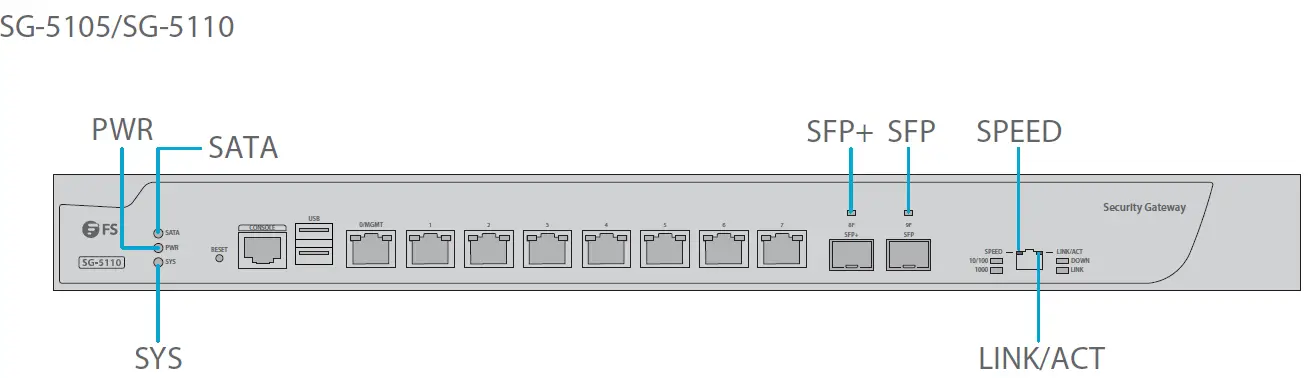
| LEDs | Status | Description |
| PWR | Off | The power module is not in the position or fails. |
| Solid Green | The power module is working properly. | |
| SYS | Blinking Green | The system is being initialized. |
| Solid Green | The initialization process is complete. | |
| Solid Red | The system sends out an alarm. | |
| SATA | Solid Green | The SATA disk is installed. |
| Blinking Green | The SATA disk is reading or writing data. | |
| LINK/ACT | Solid Green | The port is connected at 10/100/1000M. |
| Blinking Green | The port is receiving or transmitting data. | |
| SPEED | Off | The port is connected at 10/100M. |
| Solid Orange | The port is connected at 1000M. | |
| SFP | Solid Green | The fiber port is connected. |
| Blinking Green | The fiber port is receiving or transmitting data. | |
| SFP+ | Solid Green | The fiber port is connected. |
| Blinking Green | The fiber port is receiving or transmitting data. |
Installation Requirements
Before you begin the installation, make sure that you have the followings:
- Phillips screwdriver.
- Standard-sized, 19″ wide rack with a minimum of 1U height available.
- Category 5e or higher RJ-45 Ethernet cables and fiber optical cables for connecting network devices.
Site Environment:
- Do not place the device in a damp or wet location. Do not let any liquid enter the chassis.
- Do not install the equipment in a dusty environment.
- Keep the device away from heat sources.
- Ensure the normal grounding of the device.
- Wear an anti-static wrist strap to install and maintain the device.
- Use UPS (Uninterruptible Power Supply) to prevent power failure and other interferences.
Mounting the Gateway
Desk Mounting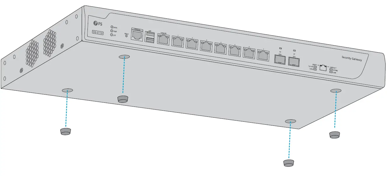
- Attach four rubber pads to the bottom.
- Place the chassis on a desk.
Rack Mounting
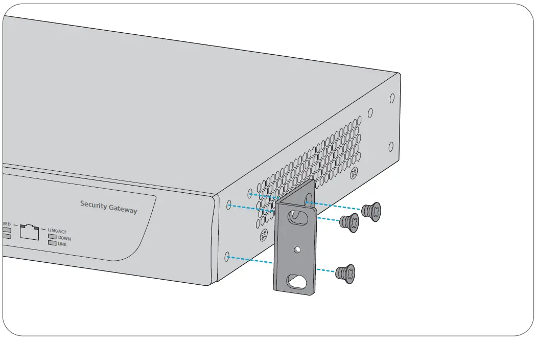
- Secure the mounting brackets to the two sides of the gateway with six M4 screws.

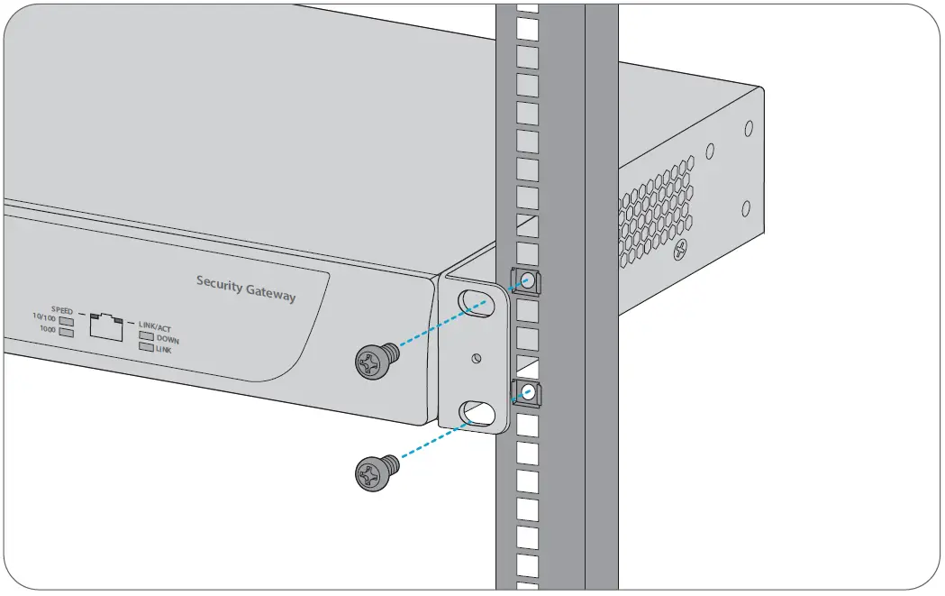
- Attach the gateway to the rack using four M6 screws and cage nuts.
Grounding the Gateway
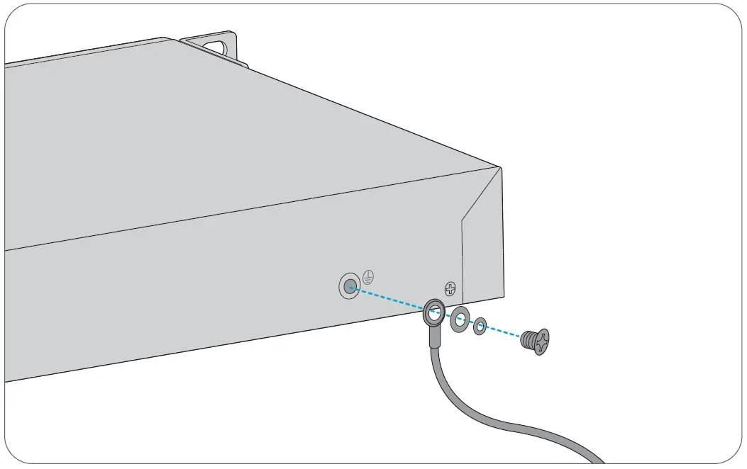
- Connect one end of the grounding cable to a proper earth ground, such as the rack in which the gateway is mounted.
- Secure the grounding lug to the grounding point on the gateway back panel with the washers and screws.
Connecting the Power
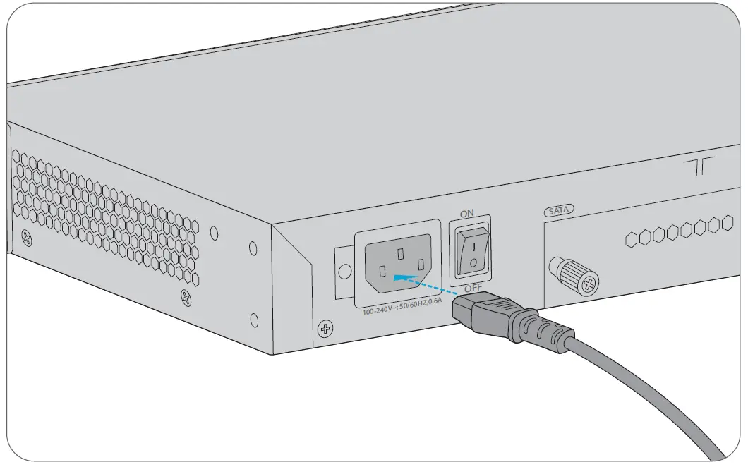
- Plug the AC power cord into the power port on the back of the gateway.
- Connect the other end of the power cord to an AC power source.
CAUTION: Do not install the power cord while the power is on, and when the power cord is connected, the fan will start to operate whether the power button is on.
Connecting the RJ45 Ports
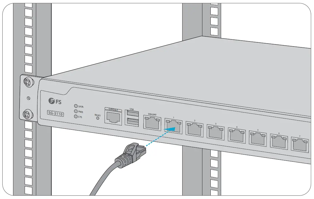
- Connect an Ethernet cable to the RJ45 port of a computer or other network devices.
- Connect the other end of the Ethernet cable to the RJ45 port of the gateway
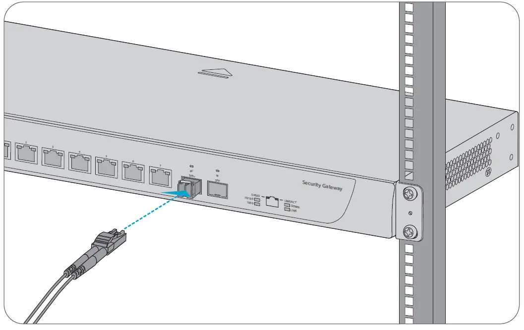
Connecting the SFP/SFP+ Ports
- Plug the compatible SFP/SFP+ transceiver into the fiber port.
- Connect a fiber optic cable to the fiber transceiver. Then connect the other end of the cable to another fiber device.
WARNING: Laser beams will cause eye damage. Do not look into bores of optical modules or optical fibers without eye protection.
 Connecting the Console Port

 Connecting the Console Port
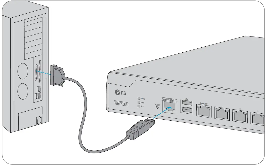
- Insert the RJ45 connector into the RJ45 console port on the front of the gateway.
- Connect the DB9 female connector of the console cable to the RS-232 serial port on the computer.
Connecting the MGMT Port
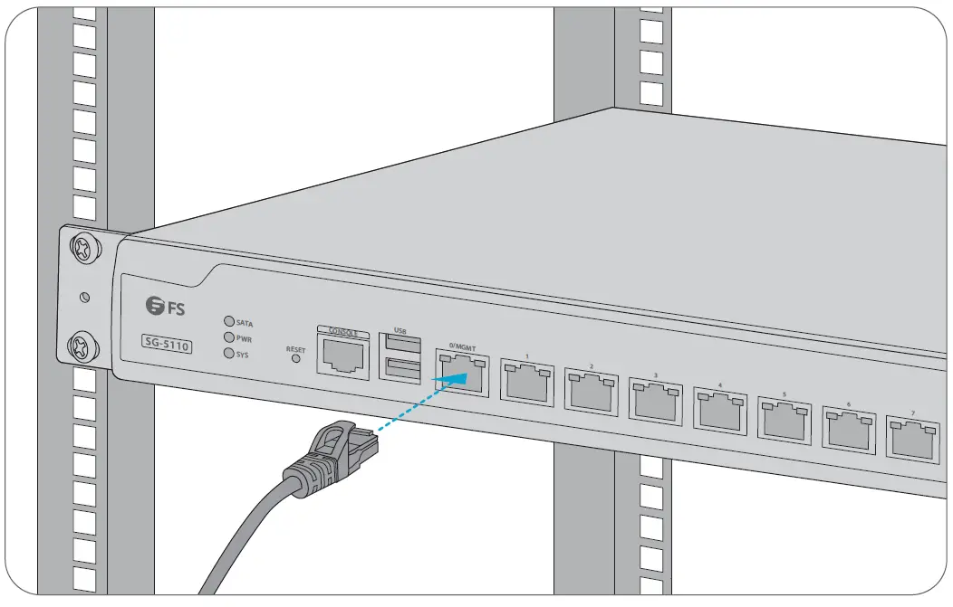
- Connect one end of a standard RJ45 Ethernet cable to a computer.
- Connect the other end of the cable to the MGMT port on the front of the gateway.
Configuring the Gateway
Configuring the Gateway Using the Web-based Interface
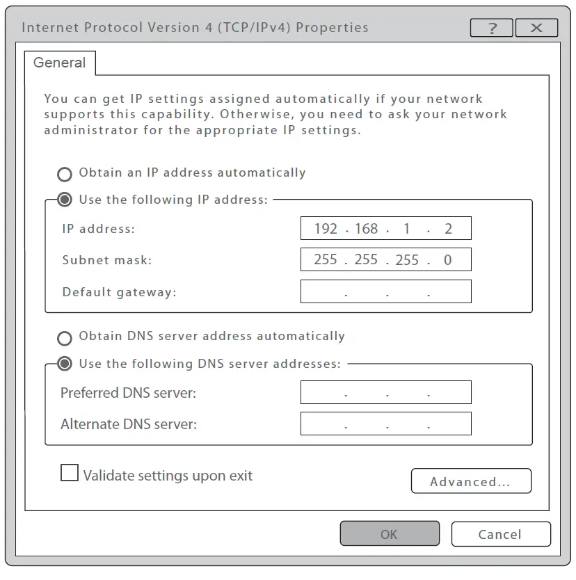
- Step 1: Connect the computer to the Management port of the gateway using the network cable.
- Step 2: Set the IP address of the computer to 192.168.1.x. (“x” is any number from 2 to 254.)

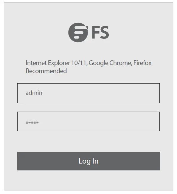
- Step 3: Open a browser, type http://192.168.1.1, and enter the default username and password, admin/admin.

- Step 4: Click Log In to display the web-based configuration page. You are then required to enter and configure a new password for the account the first time you log in.
Configuring the Gateway Using the Console Port
- Step 1: Connect a computer to the gateway’s console port using the console cable.
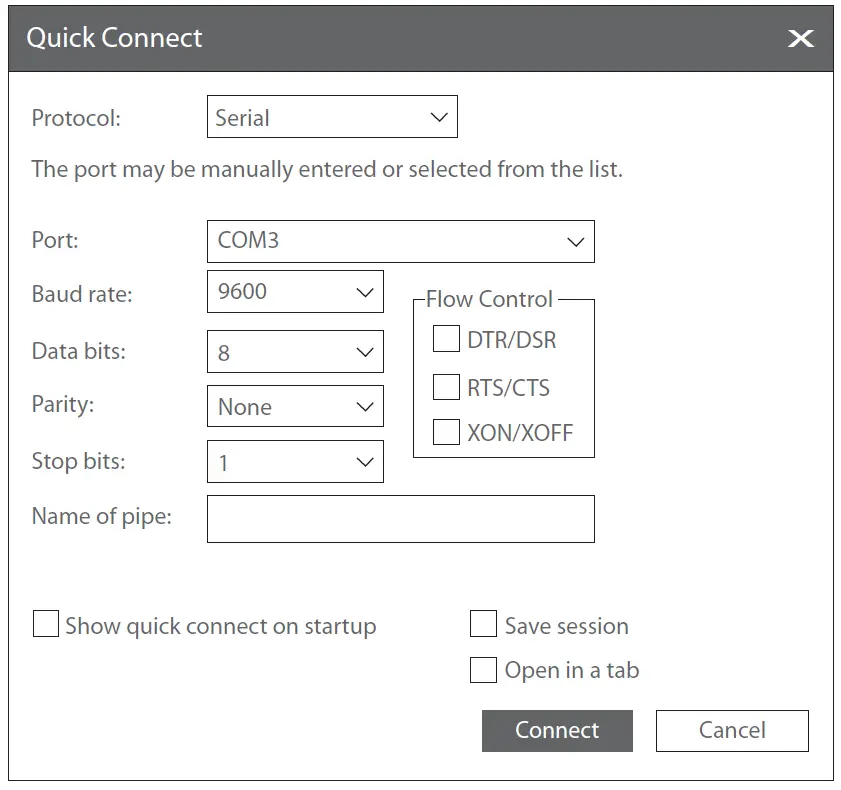
- Step 2: Start the terminal simulation software such as HyperTerminal on the computer.
- Step 3: Set the parameters of the HyperTerminal: 9600 bits per second, 8 data bits, no parity, 1 stop bit, and no flow control.

- Step 4: After setting the parameters, click Connect to enter.
NOTE: If you perform remote access via SSH and Telnet, the admin password should have already been changed since the simple password is a potential security hazard.
Troubleshooting
Power System Fault
According to the power indicator on the front panel, the gateway can be used to determine whether the power supply system of the gateway is faulty. If the power supply system is working normally, the power indicator should remain lit. If the power indicator light is unlit, please check the following:
- Whether the power switch is turned on.
- Whether the gateway power cable is connected correctly.
- Whether the cabinet power sockets are loosely connected to power modules.
WARNING: Do not plug or pull the power cable when the power switch is already turned on.
Configuration System Troubleshooting
- The console configuration terminal shows a 1. Make sure the power supply is correctly connected and powered on.
- Verify the Console cable is connected properly.
- Ensure the terminal configuration settings are correct. system booting message when the device is powered on. If the configuration system has failed, it displays error information or nothing at all. If the configuration terminal shows no information, please check the following:
Troubleshooting for Terminal Show Error Codes
If the configuration terminal shows error codes, it is likely that the terminal (such as HyperTerminal) parameters are set incorrectly. Please confirm the parameters of the terminal (such as HyperTerminal).
Support and Other Resources
- Download: https://www.fs.com/download.html
- Help Center: https://www.fs.com/download.html
- Contact Us: https://www.fs.com/contact_us.html
Product Warranty
FS ensures our customers that any damage or faulty items due to our workmanship, we will order a free return within 30 Days from the day you receive your goods. This excludes any custom-made items or tailored solutions.
Warranty: FS gateways enjoy 3 years limited warranty against defects in materials or workmanship. For more details about the warranty, please check at https://www.fs.com/policies/warranty.html
Return: If you want to return an item(s), information on how to return can be found at https://www.fs.com/policies/day_return_policy.html


