SIMARINE CARAVAN SPDU-52 Master Power Unit 
Introduction
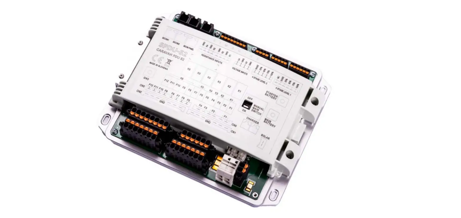
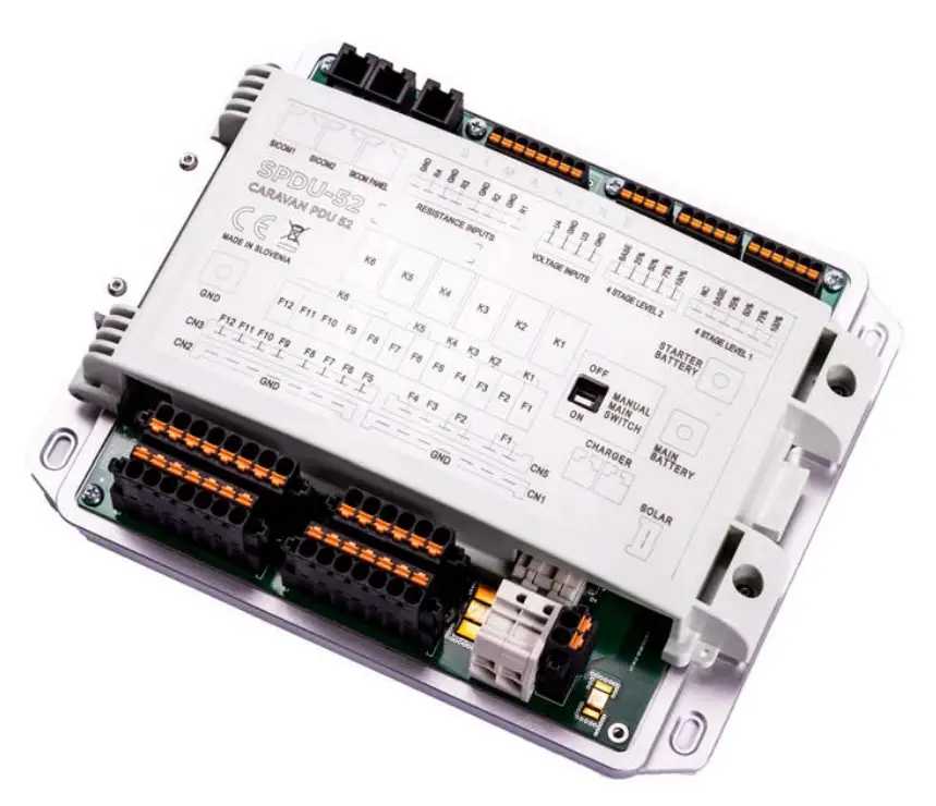
- The submarine SPDU-52 power distribution unit is a very versatile module. Its purpose is to power other modules and shunts, which are used by the Caravan Panel.
- The SPDU-52 has 3 SICOM ports, two for additional power outputs input/outputs (SICOM 1, SICOM 2) and one for the Caravan Panel (SiCOM PANEL).
- The SPDU-52 has two batteries (main and starter Battery), the voltage output is 8–22 VDC, and the temperature range is from –10 to +70°C (from +10 to +160°F).
- SPDU-52 also has 4 channels (Solar, Charger, Main battery, Starter battery) that measure current. The accuracy is ± 2%.
- The voltage measured on any of these channels is 0–35 VDC with an accuracy of ±0,5%.
- The resistance measuring on any of these channels is 0–65kohm with an accuracy of ±3%.
- The SPDU-52 with additional modules can connect up to 6 batteries, 24 shunts, 10 temperature sensors, 14 tank level sensors, 2 inclinometer sensors.
Safety
- Only qualified electricians with proper safety equipment should make installation of Simarine electronics. When working with batteries, you should wear protective clothing and eye protection.
- CAUTION: Batteries contain acid, a corrosive, colorless liquid that can burn your eyes, skin, and clothing. Should the acid come in contact with eyes, skin, or clothing, wash it immediately under fresh water for at least 15 minutes and seek medical support immediately.
- CAUTION: Do NOT connect anything to a damaged battery. It could heat up, catch fire, or explode.
- CAUTION: Lead-acid batteries can generate explosive gases during operation. Never smoke, allow flames, or sparks near the battery. Make sure to keep sufficient ventilation around the battery.
- CAUTION: When working with a battery, remove all personal metal items like watches, rings, necklaces, and bracelets. Metal items in contact with the battery terminals might cause a short circuit with a very high electric current, which may heat up and melt nearby objects and cause severe burns.
Overview
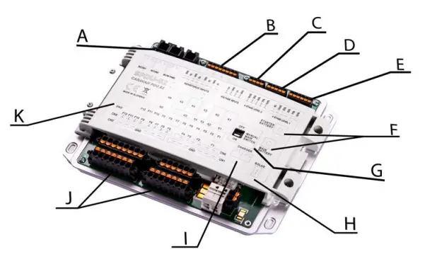
- 2 items, 1 SiCOM Panel C – voltage inputs
- 4 stage level 1
- manual main switch
- charger
- common ground
- resistance inputs
- 4 stage level 2
- main and starter battery
- solar charger
- inputs and outputs
Installation
Mounting
- CAUTION: Install the power unit in a clean and dry place protected from accidental spilling of liquids.
- Remove the shunt cover by unscrewing two screws on top of the power unit cover.
- To install the power unit using supplied voltage cables find a place no further than 3 m away from the battery/battery bank.
- You can fix the power unit with the supplied screws using four holes (two on each side) on bottom of the casing.
Cables
CAUTION: Failure to observe the required cable cross-sections can damage the shunt, wiring, or cause a fire.
SiCOM data cable:
For the AACOM connection use the supplied cable.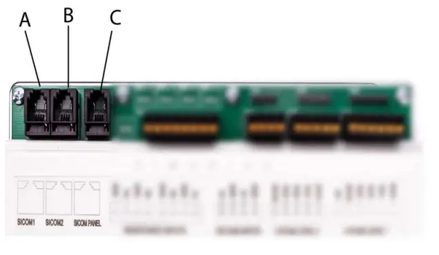
- Cable length C
- Cable length
- < 5m
- >= 5m
- Cable type
- No limitations
- 2x2x0.25 mm2 twisted pair (recommended)
SICOM Panels
- SiCOM1 port, used for an optional power input (e.g. extra port to connect a SIMARINE module).
- SiCOM2 port, used for optional power input.
- SiCOM PANEL port, used to connect the Caravan Panel.
Resistance & Voltage Inputs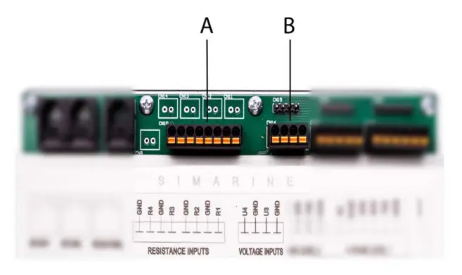
- Resistance inputs, the cable arrangement doesn’t matter because the cable used here is black (the black cable goes to R and GND).
- The resistance inputs are for potential connections that are resistance-based (e.g. tanks, freezers, etc.).
- Voltage inputs, are used for user sensors. The voltage range is from 0 to 75V (the red cable goes to U4 and U3, the black cable goes to GND).
Stage Level 1 & 2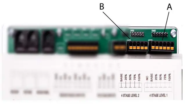
- A – 4 stage level 1, all sensors are connected to the base and individual sensors to the 25%, 50%, 75%, and 100% input. The NC stands for “not connected”, meaning it doesn’t require input.
- B – 4 stage level 2, the same as the 4 stage level 1 sensor, sensors connected to the base and individual sensors to the 25%, 50%, 75%, and 100% input.
- Cables: Red goes to the base input, black goes to the rest of the inputs (25%, 50%, 75%, 100%).
Batteries, Chargers, Ground, Main Switch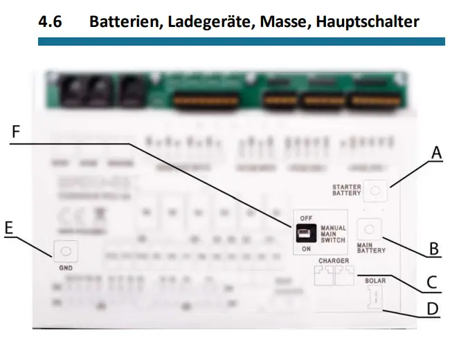
- starter battery, (current: 50A).
- main battery, (current: 50 A) – has the same current as the solar panel, charger.
- charger, (current: 40 A) – connect to the main battery and main ground (GND). The charger has the same current as the solar panel and the main battery.
- solar charger, (current: 16A).
- ground – connect each module that requires to be grounded to the GND. F – Manual main switch, turn the power of the SPDU-52 ON or OFF.
Note: Charger, solar panel and main battery all have the same current.
Relays, Inputs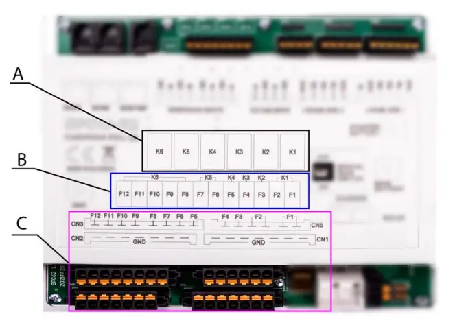
A – Relays K1-K6
The configuration for the functionality of the K1–K6 buttons can be changed in the program. The default settings however, are the following:
- K1 – Fridge
- K2 – Heating
- K3 – AC
- K4 – Aux
- K5 – Water pump
- K6 – Lighting
B – Connections
C – Connection inputs and outputs
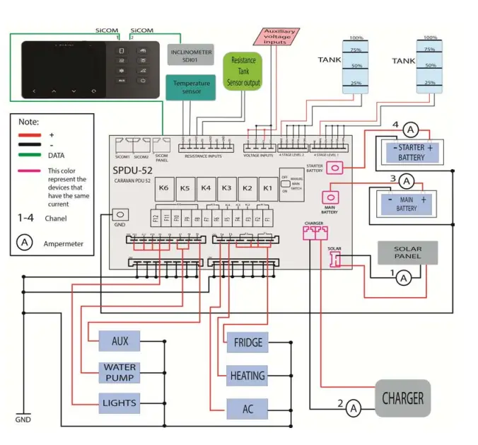
Connecting
- The Caravan Panel must be connected to the third port on the SPDU-52 (SICOM PANEL) or it will not work.
- If you have an Inclinometer module you can connect it directly to the second part of the Caravan Panel or you can connect the module to SiCOM port 1 or SiCOM port 2.
- Resistance inputs can be used to connect the temperature sensor, resistance tank sensor, the 4 stage level tank, any resistance-based sensor, etc.
- Auxiliary voltage input can be used to connect any sensor that outputs voltage.
- 4 stage levels 1 & 2, each pin is connected to a percentage mark (25%, 50%, 75%) and one is connected to base input for power. The NC in the 4 stage level 1 stands for “not connected” and does not require an input.
- Starter & main battery must be connected to the ground on the SPDU-52
- (black cable connected to GND).
- The charger and solar charger both have to be connected to the main battery and common ground (GND on SPDU-52).
- F1–F12 is connected to any external devices.
- For example, F1 and F2 ports are connected to the main battery. F3 connects to the heating and so on.
(You can find the information of all relay connections on the physical cover of the SPDU-52 or under the Diagram section)
Diagram
Technical specifications
| SPDU-52 | |
| Operating | |
| Voltage range | |
| Main battery | 8–22VDC |
| Starter battery | 8–22VDC |
| Temperature range | F) |
| Power consumption at 12V | |
| Operating | 15mA |
| Power off | 0,25mA |
| Current measuring | |
| Channel 1 (solar) | 0–16A |
| Channel 2 (charger) | 0–40A |
| Channel 3 (main battery) | 0–50A |
| Channel 4 (starter battery) | 0–50A |
| Accuracy | ±2% |
| Resolution | ±0.1 A |
| Sample rate | 100ms |
| Voltage measuring on any channel | |
| Range | 0–35VDC |
| Accuracy | ±0,5% |
| Resolution | 10mV |
| Resistance measuring on any channel | |
| Range | 0–65kohm |
| Accuracy | ±3% |
| Resolution | 1ohm |
| Temperature measuring (on resistance inputs) | |
| Temperature sensor | NTC 5K |
| Range | From -15 to +80 °C (from +10 to +160° F) |
| Resolution | 3% |
| Maximum continuous current for output channels | |
| K1 | 20A |
| K2 | 20A |
| K3 | 15A |
| K4 | 15A |
| K5 | 10A |
| K6 | 10A |
| All channels simultaneously | 50A |
| Contact continuous current rating | |
| Outputs F1–F12 | 20A |
| Charger | 40A |
| Solar | 16A |
| Dimensions (without connector) | |
| SPDU-52 | 200 x 160 x 42 mm 7,87 x 6,3 x 1,65in |
| Caravan Panel | 157 x 82 x 25 mm 6.18 x 3.23 x 0.22in |
| System capabilities (with additional modules) | Up to |
| Batteries | 6 |
| Shunts | 24 |
| Temperature sensors | 10 |
| Tank level sensors | 14 |
| Inclinometer sensors | 2 |
| Smartphone application | 1 |
| Logger capacity | up to 3 years |
Troubleshooting
If the Caravan Panel is showing the wrong sign for the current value. Check if the shunts are correctly installed. This means the consumers/generators minus (optionally plus) the terminal is connected to the IN terminals on the shunts. If this is not the case, you can reinstall the shunts or simply switch the IN and OUT terminal via the shunt configuration on the Caravan Panel.
Shunt Sensors are not visible
If the shunt sensor is not visible in the Caravan Panel menu, check the following:
- Is the Caravan Panel properly connected to the SiCOM PANEL port (the Third port on SPDU-52)? If you are using your own SiCOM cable, make sure it has the right square and is twisted.
- Is the Inclinometer module connected properly to SiCOM port 1 or 2 on the SPDU-52 or directly to the Caravan Panel?


