![]()
![]() Duct Detector Test Tool
Duct Detector Test Tool
Instruction Manual
Hand-Held Digital
Monometer
Model: 8252
![]()
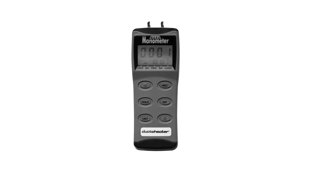
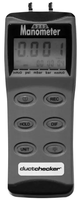
Congratulations on your purchase of the ductchecker™ Duct Detector Test Tool. This digital manometer is a portable, battery operated pressure measuring device.
The ductchecker™ is ideal for Fire Testing Technicians measuring pressure levels i n HVAC/R ducts containing smoke detectors.
INTRODUCTION
![]() The meter will display all LCD segments when it is first turned on for approx. 3 seconds.
The meter will display all LCD segments when it is first turned on for approx. 3 seconds.
Note: Though you might see DATALOGGER, Y/M/D, REL, AVG, these are not available on this meter.![]() The LCD is divided in to two distinct sections: One large (primary) top screen and one smaller right – bottom screen (relative Clock). The two display areas keep you constantly updated with the pressure measurements.
The LCD is divided in to two distinct sections: One large (primary) top screen and one smaller right – bottom screen (relative Clock). The two display areas keep you constantly updated with the pressure measurements.![]() The meter measures:
The meter measures:
Gauge pressure – a measurement of pressure that is referenced to ambient pressure.
Differential pressure – a measurement of difference of two pressures.![]() The meter has five selectable units of measure: InH2O, psi, mbar, bar, mmHz2O.
The meter has five selectable units of measure: InH2O, psi, mbar, bar, mmHz2O.![]() Please check tubing is not leaking or damaged before using.
Please check tubing is not leaking or damaged before using.
CONVERSION & RESOLUTION
| 1 mbar= | Resolution | |
| Inch of H2O | 0.401 | 0.01 |
| psi | 0.0145 | 0.004 |
| mbar | 1 | 0.1 |
| mm of H2O | 10. | 1 |
MANOMETER QUICK START
![]() Unscrew the battery compartment on the rear of instrument and fit PP3 (or equivalent) battery. Replace the cover and secure with the screw.
Unscrew the battery compartment on the rear of instrument and fit PP3 (or equivalent) battery. Replace the cover and secure with the screw.![]() Press
Press ![]() to switch the instrument on.
to switch the instrument on.![]() Press
Press ![]() to select the unit of pressure measurement required. Zero by pressing
to select the unit of pressure measurement required. Zero by pressing ![]() and hold for 3 seconds. The instrument now reads gauge pressure.
and hold for 3 seconds. The instrument now reads gauge pressure.![]() Press
Press![]() for differential pressure measurement.
for differential pressure measurement.![]() Press
Press![]() to freeze reading. Press
to freeze reading. Press ![]() again to cancel feature.
again to cancel feature.![]() Press
Press![]() to start clock. Press
to start clock. Press![]() again to see time (since start of recording). For MAX reading press
again to see time (since start of recording). For MAX reading press![]() again to see time (since start of recording). For MIN reading pressing
again to see time (since start of recording). For MIN reading pressing ![]() again returns to real time recording mode.
again returns to real time recording mode.![]() Press and hold
Press and hold ![]() for 3 seconds to turn clock feature off.
for 3 seconds to turn clock feature off.
Note:
Clock feature available with gauge pressure only not differential. The instrument will automatically switch off after 20 minutes unless sleep mode is disabled, see page 5 UTO POWER OFF.![]() Press GD for display backlight -illuminates for approximately 30 seconds and automatically switches off.
Press GD for display backlight -illuminates for approximately 30 seconds and automatically switches off.
CONTROL & INDICATORS
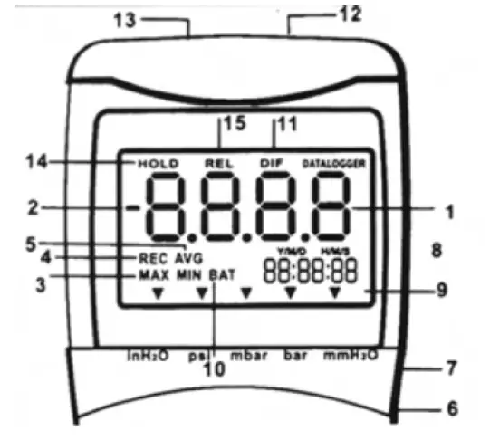
- Primary Data Screen displays pressure value.
- “-“ Minus pressure display.
- MAX MIN Pressure recorded.
- REC Starts recording mode and displays max/min pressure recorded.
- AVG Average records (N/A).
- DC Power i n Jack.
- RS232 Output port
- H/M/S 88:88:88 Displays time for Hour/Minute/Second.
 Pressure unit indication
- BAT Battery low indicator.
- DIF Differential pressure mode
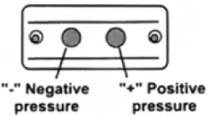
- “+” Positive pressure connection
- “-“ Negative pressure connection
- HOLD Freezes pressure reading.
- REL(N/A) Establish a relative zero for the primary screen information.
AUTO POWER OFF (SLEEP FUNCTION)
This instrument will shut off automatically after approx. 20 minutes for every power on. For recording o r operating over longer periods of time, you can disable the sleep mode by pressing ![]() and
and![]() simultaneously before power on.
simultaneously before power on.
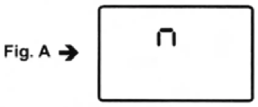
An “n” will appear in the middle of the screen at which time you can release the ![]() button (see Fig. A). The disable sleep mode will be invalid after power on.
button (see Fig. A). The disable sleep mode will be invalid after power on.
MODE OPTIONS
Delete and replace with programmable user selectable start-up mode. The display will default to the mode last used.
The following table lists the modes of operation that can be invoked by pressing the button indicated.
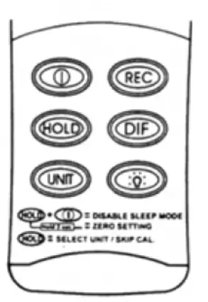
![]() Turns instrument on (default setting) and off.
Turns instrument on (default setting) and off.![]() Press momentarily and relative clock starts in the lower right screen.
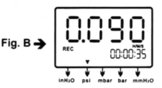
Press momentarily and relative clock starts in the lower right screen.
REC is displayed i n the middle left of screen (Fig. B). Other button functions are locked out except Power, Unit and Backlight.
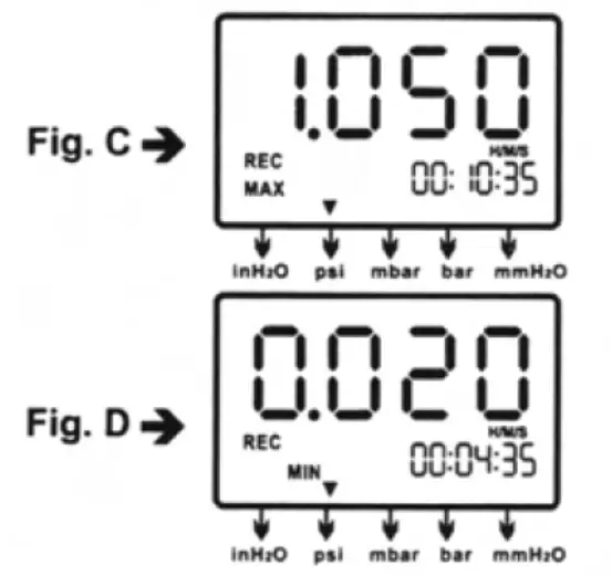
Press momentarily again and the unit cycles through MAX ( F i g . C) and MIN (Fig. D) and back to current pressure; the record mode is displayed on the LCD. Press and hold ![]() ® for 3 seconds to turn off the record function and return to normal mode.
® for 3 seconds to turn off the record function and return to normal mode.
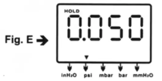
![]() Press momentarily to freeze the pressure recording ( F i g . E).
Press momentarily to freeze the pressure recording ( F i g . E).
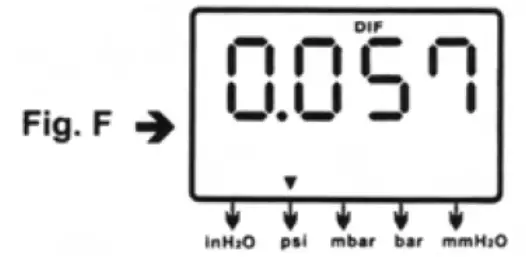
![]() Press momentarily, DIF appears on top of the LCD and the display indicates the relative zero (relative zero causes the value of the display to show as “0.0”) – only the amount of pressure change will be indicated. Press momentarily again and the unit returns to the normal mode of pressure differential (see Fig. F).
Press momentarily, DIF appears on top of the LCD and the display indicates the relative zero (relative zero causes the value of the display to show as “0.0”) – only the amount of pressure change will be indicated. Press momentarily again and the unit returns to the normal mode of pressure differential (see Fig. F).
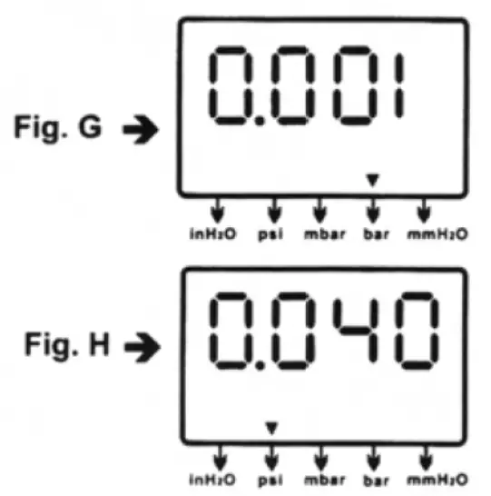
Differential Pressure: a measurement of the difference between two pressures, i.e. use differential pressure sensor to measure gauge pressure by leaving one process connection open to the atmosphere and connecting the second sensor port to your system.![]() Press momentarily and the unit will cycle through “InH2O0”, “psi”, “mbar”, “mmHz2O” which are indicated on the bottom of the display (see Fig. G & H).
Press momentarily and the unit will cycle through “InH2O0”, “psi”, “mbar”, “mmHz2O” which are indicated on the bottom of the display (see Fig. G & H).
![]() Press momentarily and the backlight illuminates for approx. 30 seconds then turns off automatically. Or press momentarily to decrease the figure when calibration is being performed.
Press momentarily and the backlight illuminates for approx. 30 seconds then turns off automatically. Or press momentarily to decrease the figure when calibration is being performed.
MAINTENANCE
![]() The meter is calibrated in-house before shipping.
The meter is calibrated in-house before shipping.![]() When properly maintained, the meter will maintain its accuracy to specification. To ensure your meter is performing at its peak, send it to the factory or a qualified
When properly maintained, the meter will maintain its accuracy to specification. To ensure your meter is performing at its peak, send it to the factory or a qualified
instrument calibration facility for annual calibration.![]() Recommended – always set to zero before measurement. Refer to the zero setting procedure on page 11.
Recommended – always set to zero before measurement. Refer to the zero setting procedure on page 11.
Cleaning:
Use a damp cloth and mild soap to clean the case of the Monometer. Do not use harsh detergents o r abrasives as these may mar the finish o r damage the unit’s case with an adverse chemical reaction.
CALIBRATION MODE
Calibration mode is only applicable for a standard manometer calibrator or any qualified calibration facility for annual calibration.
- Manually set the display to zero (no pressure applied to the connector), refer to the manual zero procedure (see page 11).
- Turn the meter off.
- Press
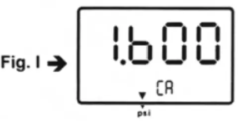
 & simultaneously. “CA” appears on the display. (see F i g . 1 ) and the meter enters the calibration mode. Make sure the unit is set on “PSI” to start positive (+) pressure calibration.
- The meter has defaulted to 1.6 psi calibration point, the adjustable pressure range is from 1.5 to 1.7 psi. If calibration pressure source is not 1.6 psi, increase by pressing
 key, or decrease by pressing
  key to set calibration point as required.
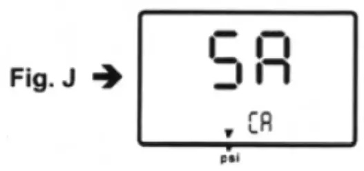
 - Save the calibration point by pressing key. “SA” and small “CA” appears on the display (see Fig. J). After 2 seconds, the meter auto-skips to the negative pressure
(-) point for ther next calibration mode.
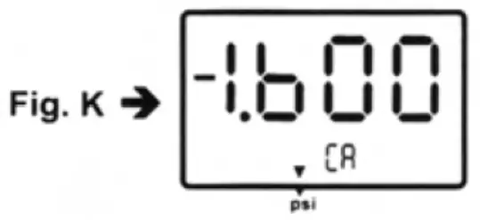
- Follow the same procedure as in step 4 for the negative pressure calibrator point. The LCD now displays “- 1.600” and a small “CA” (see Fig. K). Do the necessary calibration figure referring to your pressure standard if needed.

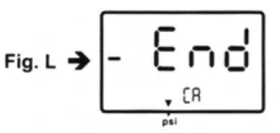
- Again save the calibration point by pressing key, “SA” and “CA” appears in 2 seconds and then pressing
 “End” and “CA” appears i n another 2 seconds. The meter turns back to the normal mode (see Fig. L).
If you can’t save by pressing the ![]() key, i.e. no “SA” appeared, please check: (a) the calibration pressure source is between 1.5 and 1.7, or (b) if you entered the correct positive pressure (+) or negative pressure (-).
key, i.e. no “SA” appeared, please check: (a) the calibration pressure source is between 1.5 and 1.7, or (b) if you entered the correct positive pressure (+) or negative pressure (-).
If you want to skip positive (+) calibration when i n calibration mode, press ![]() to skip to negative (-) calibration point.
to skip to negative (-) calibration point.
Calibration point reference
| psi | Calibration | Recommended |
| range | point(+) | (+) |
| 0~+2 | 1.6 | 1.5~1.7 |
MANUAL ZERO SETTING
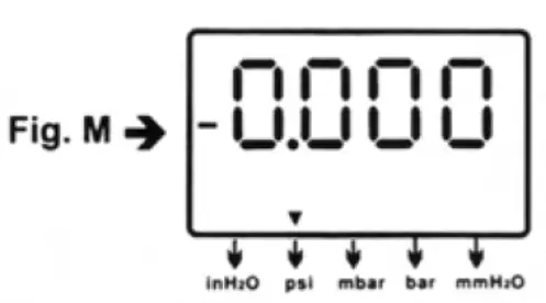
When you set the display to zero (no pressure applied to the connector), press ![]() for 2 seconds. Now the meter displays “-0.000” from right to left (see Fig. M), then
for 2 seconds. Now the meter displays “-0.000” from right to left (see Fig. M), then
the LCD display shows a normal mode.
TROUBLESHOOTING
? Power on but no display. Check the battery connections. Replace with new battery or attach optional AC adaptor.
? BAT indication. Replace with a new battery when LCD displays BAT at the middle bottom.
? No display. Make sure battery is not empty. I f the display disappears, check sleep mode is active. Refer to the disable sleep mode function for a long time on page 4. Or check the tubing is connected to the meter tightly.
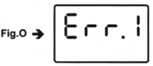
? Err.1. For the pressure value exceeding the maximum range, “Err.1” appears on the display (see Fig. O). Do not exceed above the rated pressure range of Manometer. The sensor will be damaged.
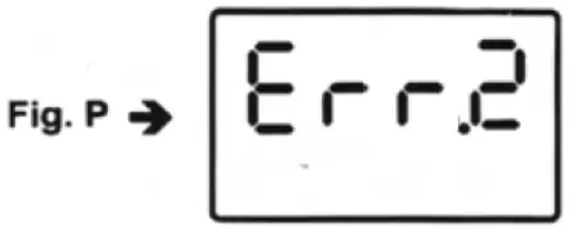
? Err.2. For the measurement of pressure less than minimum range, “Err.2″ will appear (see F i g . P).
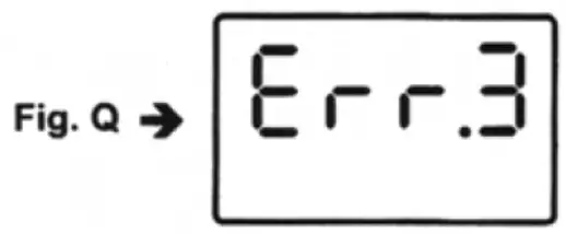
? Err.3. For a differential pressure value larger than maximum display, “Err.3″ appears on the display (see Fig. Q).
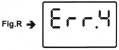
? Err.4. When you set zero, make sure you have disconnected the tubing. I f “Err.4″ appears on the display, it means the Manometer is damaged (see Fig. R).
Note: “Err.4” will also appear if the tubing is connected during Zero setting.
? E1OL or E2OL. When you see these errors while operating the RS232 software, it means the pressure source is less than or over the range of the instrument.
REPLACING THE BATTERY
Replace your 9-volt battery when:
![]() The BAT icon appears o n the right of the screen.
The BAT icon appears o n the right of the screen.![]() The meter will not power on.
The meter will not power on.![]() Use of the backlight causes the BAT icon to appear.
Use of the backlight causes the BAT icon to appear.
Even if the battery was recently replaced, check its voltage level if you get no response from the instrument.
To replace the battery:
- Remove the tubing from the instrument.
- Lay the instrument face-down on a clean, flat surface.
- Remove the battery cover.
If you do not intend to use the instrument for a month or more remove the battery. Do not leave battery i n the instrument.
OPERATING CONDITIONS
![]() Compensated temperature range: 0~50°C (32~122°F)
Compensated temperature range: 0~50°C (32~122°F)![]() Operating temperature range: 0~50°C (32~122°F)
Operating temperature range: 0~50°C (32~122°F)![]() Storage temperature range: -20-60°C (-4~140°F)
Storage temperature range: -20-60°C (-4~140°F)![]() Operating Humidity M a x . 80% RH
Operating Humidity M a x . 80% RH![]() Power: One 9.0 volt battery
Power: One 9.0 volt battery![]() Exceeding maximum pressure will Cause permanent sensor damage.
Exceeding maximum pressure will Cause permanent sensor damage.
MATERIAL SUPPLIED
This package contains:
![]() The Manometer
The Manometer![]() Battery (9.0 volt)
Battery (9.0 volt)![]() Operation manual
Operation manual![]() Connection tube 6mm (ID) x 9mm (OD) x 500mm length x 2 pcs.
Connection tube 6mm (ID) x 9mm (OD) x 500mm length x 2 pcs.
OPTIONAL ACCESSORIES
![]() RS232 software CD with D-sub connector
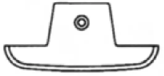
RS232 software CD with D-sub connector![]() Rubber boot
Rubber boot
SPECIFICATION
| Pressure | ||
| Range | 0- ± 138 = 0- ± 55.4 = 0- ± 1410 = 0- ± 0.138 = 0- ± 2 | mbar inH2O mm inH2O bar psi |
| Resolution | See Page 2 data sheet | |
| Accuracy | ±0.3%of full scale at ±25°C | |
| Dimensions | 72 x 182 x 30mm (meter) | |
| Unit Weight | Approz. 220 gram (with battery) | |
| Response time | 0.5 seconds | |
| Format | Baud Rate: 2400 bit/sec Data Bit: 8, Stp Bit: 1 P XXXXX, P – XXXXX (unit) | |
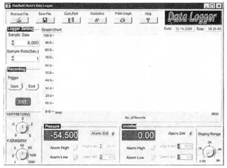
RS232 DATA OUTPUT
This Manometer can link with a personal computer to capture online data, display pressure records with real-time output. You can retrieve files, save the data for operating data analysis, record statistics, multi- file display on the screen etc. – versatile functions of your choice.
Connection Procedures:
- Plug the optional accessory RS232 cable into the DC jack port (at the right side of the meter).
- Insert the D-sub 9P type connector into the computer’s Com. 1 or 2 port.
- Start the set up of RS232 software by inserting the CD-ROM
- When installing the RS232 software, please follow the operation manual procedure in the software package.
![]()


